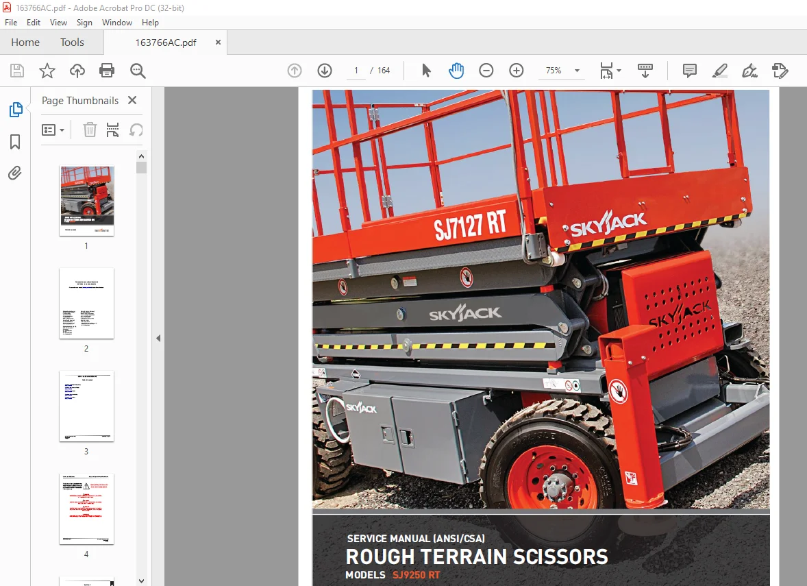
Skyjack SJ9250 RT ROUGH TERRAIN SCISSORS SERVICE MANUAL 163766AC – PDF DOWNLOAD
$26.95
Skyjack SJ9250 RT ROUGH TERRAIN SCISSORS SERVICE MANUAL 163766AC – PDF DOWNLOAD
Serial Number(s):
SJRT 9250 50 001 024 to 50 001152
Description
Skyjack SJ9250 RT ROUGH TERRAIN SCISSORS SERVICE MANUAL 163766AC – PDF DOWNLOAD
FILE DETAILS:
Skyjack SJ9250 RT ROUGH TERRAIN SCISSORS SERVICE MANUAL 163766AC – PDF DOWNLOAD
Language : English
Pages :164
Downloadable : Yes
File Type : PDF
DESCRIPTION:
Skyjack SJ9250 RT ROUGH TERRAIN SCISSORS SERVICE MANUAL 163766AC – PDF DOWNLOAD
Serial Number(s):
SJRT 9250 50 001 024 to 50 001152
and dimensions are subject to change without notice.
Aerial Platform Definition
A mobile device that has an adjustable position platform supported from ground level by a structure.
Purpose of Equipment
The SKYJACK Rough Terrain’s mid and full size aerial platforms are designed to transport and raise personnel, tools
and materials to overhead work areas.
Use of Equipment
The aerial platform is a highly maneuverable, mobile work station. Lifting and driving must be on a flat, level,
compacted surface. It can be driven over uneven terrain only when the platform is fully lowered.
Manuals
Operating
The operating manual is considered a fundamental part of the aerial platform. It is a very important way to
communicate necessary safety information to users and operators. A complete and legible copy of this manual
must be kept in the provided weather-resistant storage compartment on the aerial platform at all times.
Service & Maintenance
The purpose of this is to provide the customer with the servicing and maintenance procedures essential for
the promotion of proper machine operation for its intended purpose.
All information in this manual should be read and understood before any attempt is made to service the machine.
The updated copy of the manuals are found on the company’s
Operator
The operator must read and completely understand both this operating manual and the safety panel label located
on the platform and all other warnings in this manual and on the aerial platform. Compare the labels on the aerial
platform with the labels found within this manual. If any labels are damaged or missing, replace them immediately.
IMAGES PREVIEW OF THE MANUAL:
TABLE OF CONTENTS:
Skyjack SJ9250 RT ROUGH TERRAIN SCISSORS SERVICE MANUAL 163766AC – PDF DOWNLOAD
Table of Contents 3
Section 1 – Scheduled Maintenance 5
Operator’s Responsibility for Maintenance 6
Aerial Platform Definition 6
Purpose of Equipment 6
Use of Equipment 6
Manuals 6
Operating 6
Service & Maintenance 6
Operator Safety Reminders 7
Electrocution Hazard 8
Safety Precautions 9
Maintenance and Inspection Schedule 13
Owner’s Annual Inspection Record 13
Replacement Parts 13
Maintenance and Service Safety Tips 13
Hydraulic System & Component Maintenance and Repair 14
Maintenance Hints 15
Railing Maintenance and Repair 15
Service and Maintenance 15
About this Section 16
Service Bulletins 16
Maintenance and Inspection 16
Maintenance Instructions 16
Tables 17
Table 1 1 Owner’s Annual Inspection Record 17
Table 1 2 Maintenance and Inspection Checklist 18
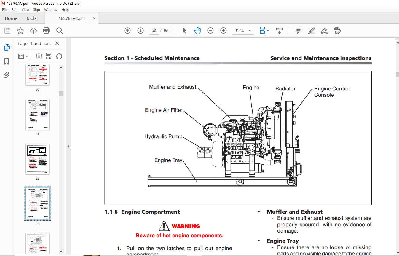
Scheduled Maintenance 19
1 1 Scheduled Maintenance Inspections 19
1 2 Function Tests 31
Section 2 – Maintenance Tables and Diagrams 41
Tables 42
Table 2 1 Specifications and Features 42
Table 2 2a Maximum Platform Capacities (Evenly Distributed) 43
Table 2 2b Maximum Platform Capacities (Evenly Distributed w/ Optional #7 Tires) 44
Table 2 3 Tire Specifications 45
Table 2 4 Floor Loading Pressure 47
Table 2 5 Fluids 48
Table 2 6 Torque Specifications 49
Table 2 7 Torque Specifications for Fasteners (Imperial) 50
Table 2 8 Torque Specifications for Fasteners (Metric) 51
Table 2 9 Torque Specifications for Hydraulic Couplings & Hoses 52
Section 3 – System Component Identification and Schematics 53
Charts 54
3 1 Hydraulic Symbol Chart 54
3 2 Electrical Symbol Chart 55
Parts List 56
3 3 Hydraulic Component Parts List 56
3 4 Electrical Component Parts List 58
Diagrams and Schematics 63
3 5 Platform Control Console Wiring – All Options (ANSI/CSA) 63
3 6 Control Cable Assemblies Diagram 64
3 7 Outrigger & Hydraulic Generator Control Console Wiring 65
3 8 Base Control Console Wiring (ANSI/CSA) 66
3 9 Hydraulic Schematic 67
3 10 Hydraulic Manifold Components & Port Identifications 68
3 11 Main Manifold Wiring Diagram 69
3 12 Emergency Lowering System Wiring Diagram (ANSI/CSA) 70
3 13 Electrical Wiring Diagram – Powered Extension Platform 71
3 14 Oil Cooler – Electrical Panel Diagram – Oil Cooler Option (ANSI/CSA) 72
3 15 Electrical Panel Diagram – Dual Fuel Engine with Hydraulic Generator Option (ANSI/CSA) 73
3 16 Electrical Panel Diagram – Diesel Engine with Hydraulic Generator Option (ANSI/CSA) 74
3 17 Auto-Leveling Outrigger Wiring Diagram 75
3 18 Horn, Light & Beeper Wiring Diagram 76
3 19 Engine Wiring Diagram – Kubota Diesel Engine 77
3 20 Electrical Panel Diagram 78
3 21 Electrical Schematic Diagram – Kubota Diesel Engine with All Option (ANSI/CSA) 79
3 22 Electrical Schematic Diagram – GM Dual Fuel Engine with All Options (ANSI/CSA) 80
3 23 Electrical Schematic Diagram – GM Dual Fuel Engine with No Options (ANSI/CSA) 81
3 24 Interface & Engine Electrical Schematic – GM Dual Fuel Engine 82
3 25 Engine Harnesses – GM Dual Fuel Engine 83
Introduction 87
Section 4 – Troubleshooting Information 85
Electrical System 88
4 1-1 All Controls Inoperative 88
4 1-2 No Power to Platform 88
4 1-3 All Functions Inoperative from Platform 88
4 1-4 Engine will Not Crank from Platform 89
4 1-5 Engine will Not Crank from Platform Controls (Additional for GM Dual Fuel) 89
4 1-6 Engine will Not Crank from Base Controls (GM dual fuel) 90
4 1-7 Engine will Not Crank from Base Controls (Kubota diesel) 90
4 1-8 Engine Cranks but Stops Cranking after a few seconds 90
4 1-9 Glow Plugs Inoperative from Engine Controls 91
4 1-10 Glow Plugs Inoperative from Platform (Additional) 91
4 1-11 Engine Cranks but will Not Start (Kubota diesel) 91
4 1-12 Engine Cranks but will Not Start (GM dual fuel) 92
4 1-13 Mid Throttle Inoperative (on demand) (GM Dual Fuel) 93
4 1-14 High Throttle Inoperative 94
4 1-15 High Throttle Inoperative (additional for GM dual fuel) 94
4 1-16 Drive and Steer Inoperative 94
4 1-17 Brakes will Not Release 95
4 1-18 Steer Right Inoperative 96
4 1-19 Steer Left Inoperative 96
4 1-20 Reverse Drive Inoperative 97
4 1-21 Forward Drive Inoperative 97
4 1-22 First Drive Speed and Steering Inoperative 98
4 1-23 Second Drive Speed Inoperative 98
4 1-24 Third Drive Speed Inoperative 99
4 1-25 High/Low Range Speed Inoperative 100
4 1-26 Up Circuit Inoperative from Platform or Base 100
4 1-27 Platform will Not Lift from Platform or Base Controls with Outriggers Extended 101
4 1-28 Platform will Not Lift from Platform or Base Controls with Outriggers Retracted 102
4 1-29 Up Circuit Inoperative from Base 103
4 1-30 Down Circuit Inoperative from Platform or Base 103
4 1-31 Down Circuit Inoperative from Base 104
4 1-32 Powered Extension Platform Inoperative 104
4 1-33 Powered Extension Platform will Not Extend 105
4 1-34 Powered Extension Platform will Not Retract 105
4 1-35 Hydraulic Generator Inoperative 105
4 1-36 Hydraulic Generator will Not Shut Off from Generator Switch 106
4 1-37 All Outriggers Inoperative (Auto-level and manual) 106
4 1-38 All Outriggers Inoperative (Auto-level and manual from platform controls) 107
4 1-39 All Outriggers Inoperative (Base Controls) 107
4 1-40 All Outriggers Inoperative (Auto-level) A: Led Power Indicator Light at Outrigger Control Module (OCM1) Not on Constant 107
4 1-41 All Outriggers Inoperative (Auto Level) B: Led Power Indicator Light at Outrigger Control Module (OCM1) Flashing 108
4 1-42 Left Front Outrigger Inoperative Manually 109
4 1-43 Right Front Outrigger Inoperative Manually 109
4 1-44 Right Rear Outriggers Inoperative Manually 109
4 1-45 Left Rear Outriggers Inoperative Manually 109
4 1-46 Individual Outrigger Functions Inoperative (Auto-level) 110
4 1-47 Auto-level Inoperative 110
4 1-48 Auto All Up Inoperative (Retract) 110
Hydraulic System 111
4 2-1 All Functions Inoperative 111
4 2-2 Steering Inoperative 111
4 2-3 Steer and First Drive Speed Inoperative 111
4 2-4 Lift and Second Drive Speed Inoperative 111
4 2-5 Drive Inoperative 111
4 2-6 Reverse Drive Inoperative 112
4 2-7 Forward Drive Inoperative 112
4 2-8 Brakes will Not Release 112
4 2-9 Up Circuit Inoperative 112
4 2-10 Down Circuit Inoperative 112
4 2-6 Reverse Drive Inoperative 113
4 2-7 Forward Drive Inoperative 113
4 2-8 Brakes will Not Release 113
4 2-9 Up Circuit Inoperative 113
4 2-10 Down Circuit Inoperative 113
4 2-11 Powered Extension Platform Inoperative 114
4 2-12 Hydraulic Generator Inoperative 114
4 2-13 All Outriggers Inoperative 114
4 2-14 Left Front Outrigger Inoperative 114
4 2-15 Right Front Outrigger Inoperative 114
4 2-16 Right Rear Outrigger Inoperative 114
4 2-17 Left Rear Outrigger Inoperative 114
4 2-18 Outriggers Drift In 115
Safety and Workmanship 118
Hydraulic System 118
Section 5 – Procedures 117
Base 118
5 1-1 Brake Caliper Adjustment 118
5 1-2 Bleeding the Brake Caliper 120
5 1-3 Changing the Hydraulic Oil 122
5 1-4 Wheel Bolt/Nut Inspection and Torquing Procedure 122
5 1-5 Wheel Reinstallation and Torquing Procedure 123
5 1-6 Front Axle Hub Procedure 123
5 1-7 Electronic Tilt Switch Setup Procedure 125
5 1-8 Reconnecting the Platform Control Box for Use from the Ground 128
5 1-9 Tightening and Torque Recommendations for Hydraulic Couplings and Hoses 129
5 1-10 Checking the Holding Valve 130
5 1-11 System Pressure Setting 131
5 1-12 Lift Pressure Setting 132
5 1-13 Grease Points 133
Engine 134
5 2-1 ECU Pin Reference Chart (GM) 134
5 2-2 Throttle Actuator (GM) 135
5 2-3 GM Map and IAT Sensor (GM) 136
5 2-4 Engine Coolant Temperature Sensor (GM) 137
5 2-5 LPG Temperature Sensor (GM) 138
5 2-6 Fuse Block Layout (GM) 139
5 2-7 Fan Belt Replacement and Adjustment (Kubota D1305) 140
5 2-8 Engine Throttle Setting (Kubota D1305) 141
5 2-9 Replacing the Air Cleaner Element 142
5 2-10 Replacing the Fuel Filter Element (Kubota D1305) 143
5 2-11 Bleeding the Fuel System of Air (Kubota D1305) 143
5 2-12 Replacing the Oil Filter Cartridge (Kubota D1305) 144
5 2-13 Changing the Oil (Kubota D1305) 144
5 2-14 Checking and Replenishing the Radiator Coolant Level (Kubota D1305) 145
5 2-15 Draining and Refilling the Radiator (Kubota D1305) 145
Outriggers 146
5 3-1 Auto-Leveling Outrigger PC Board Layout 146
5 3-2 Outrigger Mechanical Limit Switch Wiring Diagram 147
5 3-3 Auto-Leveling Outrigger Setting and Error Codes 148
5 3-4 Auto-Leveling Outrigger Error Code Breakdown 149
5 3-5 Hand Held Calibration/Diagnostic Tool Key Functions 150
5 3-6 Outrigger Control Module Instructions 151
5 3-7 Auto-Leveling Outrigger Control Module Pin Reference Chart 154
5 3-8 Outrigger Upper Limit Switch (LS61, LS62, LS63, LS64) Replacement and Adjustment 155
5 3-9 Outrigger Lower Limit Switch (LS65, LS66, LS67, LS68) Replacement and Adjustment 156
Scissors 158
5 4-1 End of Stroke Limit Switch (LS4) Replacement and Adjustment 158
5 4-2 High Speed Cutout (LS5) and Lift Cutout (LS1) Limit Switch Replacement and Adjustment 160
Platform 162
5 5-1 Gate Springe Hinge Adjustment 162
Need help? Contact: [email protected]
PLEASE NOTE:
- This is the SAME manual used by the dealers to troubleshoot any faults in your vehicle. This can be yours in 2 minutes after the payment is made.
- Contact us at [email protected] should you have any queries before your purchase or that you need any other service / repair / parts operators manual.
S.M