Trusted Business
Verified & Licensed
Virus Free Files
100% Safe Downloads
Secure Payment
SSL Protected
Instant Delivery
Available Immediately
Skyjack SJIII 3219 DC Electric Scissors Parts Manual 160607AG – PDF DOWNLOAD
$28.95
Skyjack SJIII 3219 DC Electric Scissors Parts Manual 160607AG – PDF DOWNLOAD
SJIII 3215 10000839 to 10000995
SJIII 3219 22032963, 22032964, 22035881, 22037437 to 22057771
Instant PDF Download
Available immediately
Save to Your Device
Download & keep forever
Antivirus Scanned
100% virus-free
Trusted Worldwide
175,000+ customers
Description
Skyjack SJIII 3219 DC Electric Scissors Parts Manual 160607AG – PDF DOWNLOAD
FILE DETAILS:
Skyjack SJIII 3219 DC Electric Scissors Parts Manual 160607AG – PDF DOWNLOAD
Language : English
Pages : 151
Downloadable : Yes
File Type : PDF
DESCRIPTION:
Skyjack SJIII 3219 DC Electric Scissors Parts Manual 160607AG – PDF DOWNLOAD
SJIII 3215 10000839 to 10000995
SJIII 3219 22032963, 22032964, 22035881, 22037437 to 22057771
General:
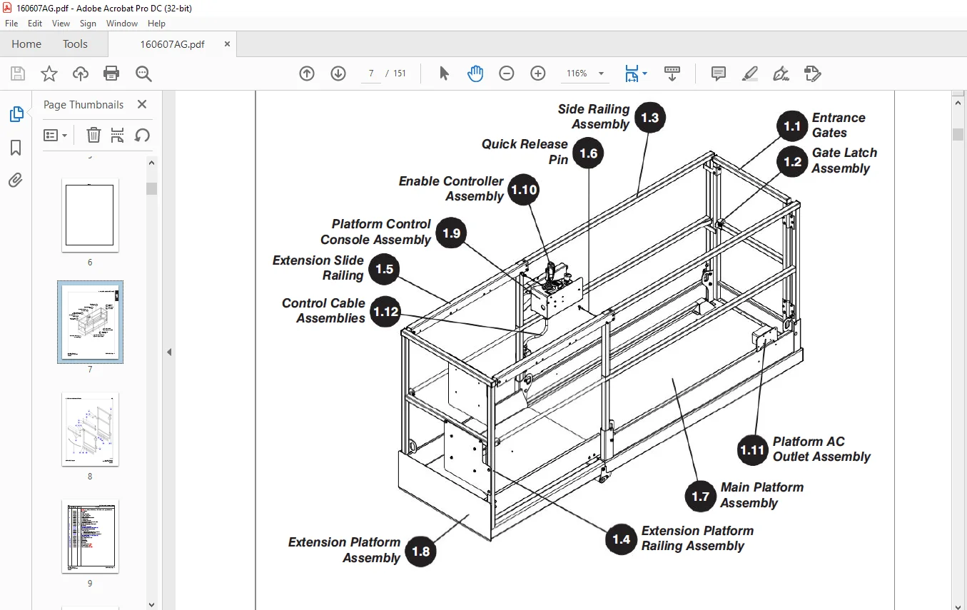
The information contained in this section is designed to aid the user in locating and identifying
replacement parts. Component parts of various assemblies and sub-assemblies comprising the
work platform are illustrated and accompanied by a descriptive parts list. Exploded drawings are
used to show relative location of component parts in disassembly order. If a part cannot be found
in this section, order by work platform model number and serial number, giving a complete
description of the part.
Parts Ordering Information:
When ordering replacement parts, the complete part number and description should be used to
ensure proper identification and delivery of the desired item. This complete identification should
also be used when requesting equipment information.
ensure proper identification and delivery of the desired item. This complete identification should
also be used when requesting equipment information.
Method of Listing:
Parts are listed in order according to the reference number shown in the illustration,
followed by a full description based upon the “NOUN FIRST” method. That is, the noun name
of the part is listed first, then the modifying description information which serves to
specifically identify the item. For example: PIN, Clevis. Assemblies or groups are shown at the
beginning of a parts list and are identified with the letter references A, B, C, etc. Individual
parts in these lists have corresponding letters after their description to identify which assembly
or group it is used in. Individual parts without identifying letters are used in all the assemblies
or group shown at the beginning of the parts list. Descriptions preceded with an (•) indicates
a serviceable component or
attaching hardware for the higher level assembly. If
an index number initially starts with the letter “K”, for example “K1”, means it’s a kit. Any
item(s) included in a kit will not have an index number.
Quantities (Units Per Assy.):
The quantities of each part that are required to complete the assembly. If quantity is (AR), it is understood that the quantity may vary when aerial platform is equipped with certain options. Order quantity as needed.
Hardware:
Standard screws, washers, nuts, etc. are not identified by
a reference number. These parts are known as COMMON HARDWARE items and appear indented under
the major items with which they are used. They should be ordered separately as listed, since they
are not component parts of the pieces they attach to.
a reference number. These parts are known as COMMON HARDWARE items and appear indented under
the major items with which they are used. They should be ordered separately as listed, since they
are not component parts of the pieces they attach to.
How to Order Repair Parts
1. Address all orders to your local SKYJACK dealer.
2. Specify model and serial number of the work platform (found on the serial number
plate).
3. List the quantity needed.
4. List the length needed (if bulk item).
5. List the part number and description as shown in this manual for each item.
6. Show billing and shipping address and name of individual if possible.
7. Suggest best routing.
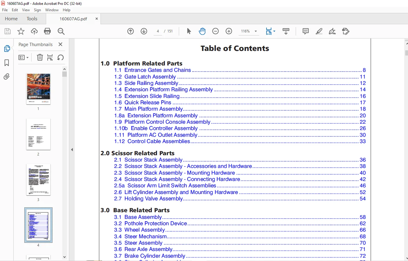
TABLE OF CONTENTS:
Skyjack SJIII 3219 DC Electric Scissors Parts Manual 160607AG – PDF DOWNLOAD
Table of Contents................................................................  4
1.0  Platform Related Parts......................................................  7
	1.1  Entrance Gates and Chains...............................................  8
	1.2  Gate Latch Assembly..................................................... 11
	1.3  Side Railing Assembly................................................... 12
	1.4  Extension Platform Railing Assembly..................................... 14
	1.5  Extension Slide Railing................................................. 16
	1.6  Quick Release Pins...................................................... 17
	1.7  Main Platform Assembly.................................................. 18
	1.8a  Extension Platform Assembly............................................ 20
	1.9  Platform Control Console Assembly....................................... 22
	1.10b  Enable Controller Assembly............................................ 26
	1.11  Platform AC Outlet Assembly............................................ 30
	1.12  Control Cable Assemblies............................................... 33
2.0 Scissor Related Parts........................................................ 35
	2.1  Scissor Stack Assembly.................................................. 36
	2.2  Scissor Stack Assembly - Accessories and Hardware....................... 38
	2.3  Scissor Stack Assembly - Mounting Hardware.............................. 40
	2.4  Scissor Stack Assembly - Connecting Hardware............................ 42
	2.5a  Scissor Arm Limit Switch Assemblies.................................... 46
	2.6  Lift Cylinder Assembly and Mounting Hardware............................ 52
	2.7  Holding Valve Assembly.................................................. 54
3.0  Base Related Parts.......................................................... 57
	3.1  Base Assembly........................................................... 58
	3.2  Pothole Protection Device............................................... 62
	3.3  Wheel Assembly.......................................................... 66
	3.4  Steer Mechanism......................................................... 68
	3.5  Steer Assembly.......................................................... 70
	3.6  Rear Axle Assembly...................................................... 71
	3.7  Brake Cylinder Assembly................................................. 72
	3.8  Steer Cylinder Assembly................................................. 73
	3.9  Free-Wheeling Manifold Assembly......................................... 74
	3.10  Hydraulic Hose Connections - Drive/Steer............................... 75
	3.11  Base Control Console Hardware.......................................... 76
	3.12  Base Control Harness and Switches...................................... 78
4.0  Hydraulic Tray Related Parts................................................ 81
	4.1  Hydraulic/Electrical Tray Assembly...................................... 82
	4.2  Main Manifold Assembly.................................................. 84
	4.3  Motor and Pump Assembly................................................. 88
	4.4  Emergency Lowering Manifold............................................. 90
	4.5  Proportional Manifold Assembly.......................................... 91
	4.6  Hydraulic Tank Lid Assembly............................................. 92
	4.7  Hydraulic Hose Connections - Controls................................... 93
5.0  Battery Tray Related Parts.................................................. 95
	5.1  Battery Tray Assembly................................................... 96
	5.2  Battery Charger - Delta-Q...............................................100
	5.3  Battery Charger - Signet................................................102
6.0  Electrical Related Parts....................................................105
	6.1  Electrical Panel and Hardware Assembly..................................106
	6.2  Electrical Panel and Hardware Assembly (ANSI/CSA EE rated)..............108
	6.3  Main Manifold Harness...................................................110
	6.4  Rear Manifold Harness...................................................112
	6.5  Horn/Flashing Light, Holding Valve, Tilt & Pressure Switch Harnesses....115
	6.6  Elevate Telematics Harness..............................................116
7.0  Optional Equipment..........................................................119
	7.1  24VDC Inverter and Hardware (ANSI/CSA)..................................120
	7.2  Inverter Assembly (ANSI/CSA)............................................122
	7.3  Air Hose to Platform Assembly...........................................124
	7.4  Black Logo Labels Option (Model SJIII 3219).............................125
	7.5  Pipe Rack Assembly (ANSI/CSA)...........................................127
	7.6  Flashing Amber Light Option.............................................128
	7.7  Dual Flashing Amber Light Option (Diagonal).............................130
	7.8  Platform Control Console - Long Cable Option (ANSI/CSA).................132
	7.9  Tool Caddy..............................................................134
	7.10  Elevate Telematics.....................................................136
	7.11  Secondary Guarding Lift Enable Kit.....................................138
8.0  Labels......................................................................139
	8.1  Label Kit...............................................................140
	8.2  Label - Platform Control Console........................................141
	8.3  Labels - Miscellaneous..................................................142
	8.4  Labels - Sides..........................................................144
	8.5  Labels - Front & Back...................................................146
	8.6  Labels - Chassis Top....................................................148
9.0  Fluid Tables................................................................149
	9.0  Fluid Table.............................................................150
IMAGES PREVIEW OF THE MANUAL:
Questions? Email us: [email protected]
PLEASE NOTE:
- This is not a physical manual but a digital manual – meaning no physical copy will be couriered to you. The manual can be yours in the next 2 mins as once you make the payment, you will be directed to the download page IMMEDIATELY.
- This is the same manual used by the dealers inorder to diagnose your vehicle of its faults.
- Require some other service manual or have any queries: please WRITE to us at [email protected]
S.V