Skyjack SJIII 3219 DC Electric Scissors Service Manual 210276AC – PDF DOWNLOAD
$28.95
Skyjack SJIII 3219 DC Electric Scissors Service Manual 210276AC – PDF DOWNLOAD
SJIII 3219 80100000 to 80149999
Description
Skyjack SJIII 3219 DC Electric Scissors Service Manual 210276AC – PDF DOWNLOAD
FILE DETAILS:
Skyjack SJIII 3219 DC Electric Scissors Service Manual 210276AC – PDF DOWNLOAD
Language : English
Pages : 105
Downloadable : Yes
File Type : PDF
DESCRIPTION:
Skyjack SJIII 3219 DC Electric Scissors Service Manual 210276AC – PDF DOWNLOAD
SJIII 3219 80100000 to 80149999
SKYJACK is continuously improving and expanding product features on its equipment, therefore, specifications
and dimensions are subject to change without notice.
Aerial Platform and Mobile Elevating Work Platform Definition:
A mobile device that has a positionable platform supported from ground level by a structure.
Purpose of Equipment:
The SKYJACK SJIII DC Electric series aerial platforms are designed to transport and raise personnel, tools and
materials to overhead work areas.
Use of Equipment:
The aerial platform is a highly maneuverable, mobile work station. Work platform elevation and elevated driving
must only be done on a firm level surface.
Manuals:
Operating:
The operating manual is considered a fundamental part of the aerial platform. It is a very important way to
communicate necessary safety information to users and operators. A complete and legible copy of this manual
must be kept in the provided weather-resistant storage compartment on the aerial platform at all times.
Service & Maintenance:
The purpose of this is to provide the customer with the servicing and maintenance procedures essential for
the promotion of proper machine operation for its intended purpose.
All information in this manual should be read and understood before any attempt is made to service the machine.
Service Policy and Warranty:
SKYJACK warrants each new SJIII Series work platform to be free of defective parts and workmanship for the first
24 months. Any defective part will be replaced or repaired by your local SKYJACK dealer at no charge for parts or
labor. Contact the SKYJACK Service Department for warranty statement extensions or exclusions.
Operator Safety Reminders, Warnings and Precautions:
Operator safety is SKYJACK’s priority. The operator should comply with all applicable safety-related reminders,
warnings and precautions found in the Operating Manual. They should be read and understood completely before
operating the aerial platform.
TABLE OF CONTENTS:
Skyjack SJIII 3219 DC Electric Scissors Service Manual 210276AC – PDF DOWNLOAD
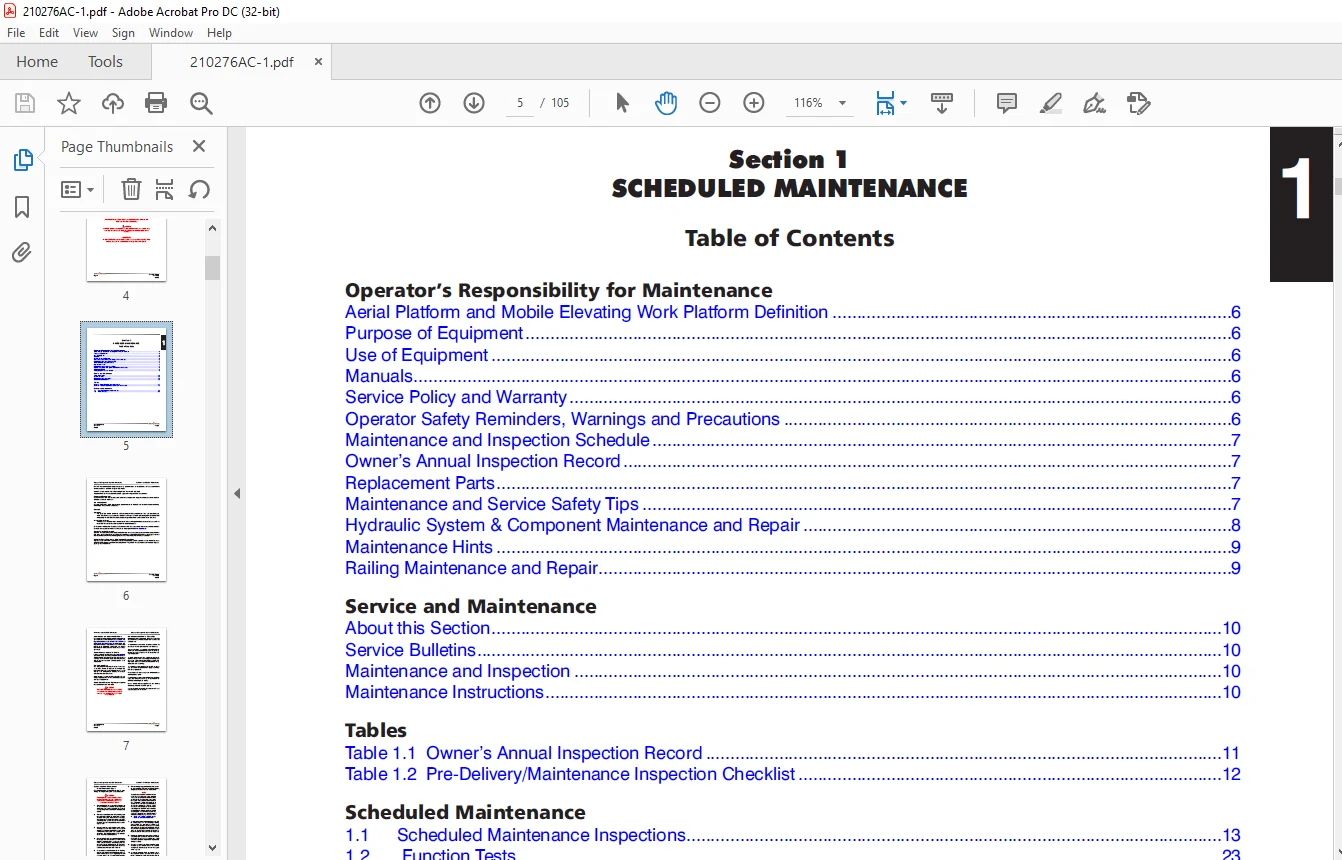
Cover......................................................................................  1
Table of Contents..........................................................................  3
Section 1 - Scheduled Maintenance..........................................................  5
	Operator’s Responsibility for Maintenance..............................................  6
		Aerial Platform and Mobile Elevating Work Platform Definition......................  6
		Purpose of Equipment...............................................................  6
		Use of Equipment...................................................................  6
		Manuals............................................................................  6
		Service Policy and Warranty........................................................  6
		Operator Safety Reminders, Warnings and Precautions................................  6
		Maintenance and Inspection Schedule................................................  7
		Owner’s Annual Inspection Record...................................................  7
		Replacement Parts..................................................................  7
		Maintenance and Service Safety Tips................................................  7
		Hydraulic System & Component Maintenance and Repair................................  8
		Maintenance Hints..................................................................  9
		Railing Maintenance and Repair.....................................................  9
	Service and Maintenance................................................................ 10
		About this Section................................................................. 10
		Service Bulletins.................................................................. 10
		Maintenance and Inspection......................................................... 10
		Maintenance Instructions........................................................... 10
	Tables................................................................................. 11
		Table 1.1  Owner’s Annual Inspection Record........................................ 11
		Table 1.2  Pre-Delivery/Maintenance Inspection Checklist........................... 12
	Scheduled Maintenance.................................................................. 13
		1.1 Scheduled Maintenance Inspections.............................................. 13
		1.2  Function Tests................................................................ 23
Section 2 - Maintenance Tables and Diagrams................................................ 25
	Tables................................................................................. 25
		Table 2.1  Specifications and Features............................................. 26
		Table 2.2  Floor Loading Pressure.................................................. 27
		Table 2.3  Maximum Platform Capacities (Evenly Distributed)........................ 29
		Table 2.4  Torque Specifications................................................... 30
		Table 2.5  Torque Specifications for Fasteners (Imperial).......................... 31
		Table 2.6  Torque Specifications for Fasteners (Metric)............................ 32
		Table 2.7  Torque Specifications for Hydraulic Couplings & Hoses................... 33
Section 3 - System Component Identification and Schematics................................. 35
	Charts................................................................................. 36
		3.1  Electrical Symbol Chart....................................................... 36
		3.2  Hydraulic Symbol Chart........................................................ 37
		3.3  Wire Number and Color Code.................................................... 38
		3.4  AC Cord Color Code............................................................ 39
	Parts List............................................................................. 40
		3.5  Hydraulic Schematic Parts List................................................ 40
		3.6  Electrical Component Parts List............................................... 41
	Diagrams and Schematics................................................................ 43
		3.7  Free-Wheeling and Holding Manifold and Port Identifications................... 43
		3.8  Main Manifold and Port Identifications........................................ 44
		3.9  Platform Control Console Diagram.............................................. 45
		3.10  Base Control Console Diagram................................................. 46
		3.11  Scissor Arm Control Cable.................................................... 47
		3.12  Platform Control Cable....................................................... 48
		3.13  Pothole Limit Switch Assembly Diagrams....................................... 49
		3.14  Telematics Harness - M6 Only................................................. 50
		3.15  Hydraulic Schematic.......................................................... 51
		3.16  Electrical Harness........................................................... 52
		3.17  Electrical Harness Wiring Diagram............................................ 53
		3.18  Telematics Wiring - MOREY.................................................... 54
		3.19  Telematics Wiring - M8....................................................... 55
		3.20  Telematics Wiring - M6 & M8.................................................. 56
		3.21  Electrical Schematic (All Options)........................................... 57
Section 4 - Troubleshooting Information.................................................... 59
	Introduction........................................................................... 60
	Electrical System...................................................................... 61
		4.1-1  All Controls Inoperative.................................................... 61
		4.1-2  All Controls Except for Down Function Inoperative........................... 61
		4.1-3  All Controls Inoperative From Base Control Console.......................... 62
		4.1-4  No Up Function from Base Control Console.................................... 62
		4.1-5  No Down Function from Base Control Console.................................. 62
		4.1-6  All Controls Inoperative From Platform Control Console...................... 63
		4.1-7  No Up Function from Platform Controls....................................... 63
		4.1-8 No Down Function from Platform Controls...................................... 64
		4.1-9 Right Steer Inoperative ..................................................... 64
		4.1-10 Left Steer Inoperative ..................................................... 64
		4.1-11 Forward Drive Function Inoperative.......................................... 65
		4.1-12 Reverse Drive Function Inoperative.......................................... 65
		4.1-13 No Drive or Steer when Platform Elevated.................................... 66
		4.1-14 Mid speed Inoperative....................................................... 66
	Hydraulic System....................................................................... 67
		4.2-1  All Function Inoperative.................................................... 67
		4.2-2  All System Sluggish......................................................... 67
		4.2-3  Platform Drifts Down........................................................ 67
		4.2-4  Platform Lifts Slowly....................................................... 67
		4.2-5  Platform does not Lift...................................................... 67
		4.2-6  Platform will not Lower..................................................... 67
		4.2-7  Platform Lowers Slowly (3215 only).......................................... 67
		4.2-8  Platform Drives Slow........................................................ 68
		4.2-9  Platform will not Drive in Forward or Reverse............................... 68
		4.2-10 Brake(s) will not Release................................................... 68
		4.2-11 Platform does not Steer..................................................... 68
Section 5 - Procedures..................................................................... 69
	Service & Maintenance.................................................................. 70
		General............................................................................ 70
		Safety and Workmanship............................................................. 70
	Service & Maintenance.................................................................. 34
	Platform............................................................................... 70
		5.1-1 OEM Controller Electronics Information....................................... 70
		5.1-2 OEM Controller Troubleshooting............................................... 71
		5.1-3 OEM Controller Switch Wiring................................................. 72
		5.1-4 Gate Spring Hinge Adjustment................................................. 73
	Base................................................................................... 75
		5.2-1 System Relief Pressure Adjustment............................................ 75
		5.2-2 Lift Pressure Adjustment..................................................... 75
		5.2-3 SKYCODED Control Module Pin Reference Chart.................................. 76
		5.2-4 Hand Held Calibration and SKYCODED Diagnostic Tool Key Functions............. 78
		5.2-5 Hand Held Calibration/Diagnostic Tool Menu Options........................... 79
		5.2-6 SKYCODED Help Messages - Quick Reference Chart............................... 89
		5.2-7 SKYCODED LED Flash Codes..................................................... 91
		5.2-8 SKYCODED Control Module - Access Level Code.................................. 92
		5.2-9 SKYCODED Control Module - Calibrate Level Procedure.......................... 93
		5.2-10 Pothole Limit Switches (LS1 & LS2) Replacement and Adjustment............... 94
		5.2-11  Wheel Replacement and Torquing Procedure................................... 95
		5.2-12 Tightening and Torque Recommendations for Hydraulic Couplings and Hoses ....102
IMAGES PREVIEW OF THE MANUAL:
Questions? Email us: [email protected]
https://vimeo.com/878166181?share=copy
PLEASE NOTE:
- This is the SAME exact manual used by your dealers to fix your vehicle.
- The same can be yours in the next 2-3 mins as you will be directed to the download page immediately after paying for the manual.
- Any queries / doubts regarding your purchase, please feel free to contact [email protected]
S.V