Sony BDP-BX2 BDP-S357 BDP-S360 BDP-S363 Blu-ray Player Service Manual PDF
Original price was: $85.00.$15.95Current price is: $15.95.
Official Sony service manual for BDP-BX2, BDP-S357, BDP-S360, and BDP-S363 Blu-ray Disc players, including RMT-B104A/B104C/B104P/B105A/B105P remote controls. This comprehensive 129-page technical manual covers all regional models (US, Canadian, UK, European, Australian, Chinese, Russian) with complete specifications, disassembly procedures, schematics, troubleshooting guides, service mode instructions, and illustrated parts lists. Essential for electronics technicians servicing Sony Blu-ray players.
Description
Sony BDP-BX2 BDP-S357 BDP-S360 BDP-S363 Blu-ray Player Service Manual PDF DOWNLOAD
DESCRIPTION:
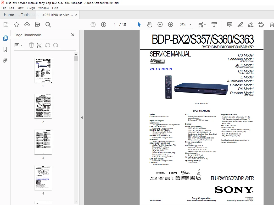
Sony BDP-BX2/S357/S360/S363 Blu-ray Disc Player – Complete Factory Service Manual
This is the official factory service manual (Version 1.3, September 2009, Document No. 9-890-708-14) published by Sony Corporation for the BDP-BX2, BDP-S357, BDP-S360, and BDP-S363 Blu-ray Disc Player models. This comprehensive technical guide provides electronics service technicians, repair shops, and home theater specialists with complete service information, repair procedures, schematics, troubleshooting guides, and parts information for these professional Blu-ray players.
File Details:
- Manual Name: BDP-BX2/S357/S360/S363 Service Manual
- Models Covered: BDP-BX2, BDP-S357, BDP-S360, BDP-S363
- Remote Controls: RMT-B104A, RMT-B104C, RMT-B104P, RMT-B105A, RMT-B105P
- Version: 1.3 (September 2009)
- Document Number: 9-890-708-14
- Publisher: Sony Corporation Quality Assurance Dept.
- Manual PDF Quality: Excellent – Factory original with detailed diagrams
- Total Pages: 129
REGIONAL MODELS COVERED:
United States & Canadian Models:
- BDP-BX2 (US, Canadian)
- BDP-S360 (US, Canadian)
European Models:
- BDP-S357 (AEP Model)
- BDP-S360 (UK, E Model)
- BDP-S363 (UK, E Model)
Asia-Pacific Models:
- BDP-S360 (Australian)
- BDP-S360 (Chinese)
- BDP-S360 (PX Model)
- BDP-S360 (Russian)
Power Requirements by Region:
- 110V AC, 60Hz (Taiwan)
- 120V AC, 60Hz (US, Canadian)
- 110-240V AC, 50/60Hz (E, PX, Saudi Arabia, Brazilian, Hong Kong, Thai)
- 220V AC, 60Hz (Korean)
- 220-240V AC, 50/60Hz (EC1, EC2, CEK, Australian, Chinese, Russian)
COMPLETE SPECIFICATIONS:
System:
- Type: Blu-ray Disc / DVD Player
- Laser: Semiconductor laser
- Optical Device: KEM-430AAA/C2RP
- Power Consumption: 22W
- Dimensions: 430 mm × 216 mm × 56 mm (17″ × 8 5/8″ × 2 1/4″) W×D×H including projecting parts
- Weight: 2.1 kg (4 lb 10 1/8 oz)
- Operating Temperature: 5°C to 35°C (41°F to 95°F)
- Operating Humidity: 25% to 80%
Inputs and Outputs:
- LINE OUT R-AUDIO-L: Phono jack, 2 Vrms, 10 kilohms
- DIGITAL OUT (OPTICAL): Optical output jack, -18 dBm (wavelength 660 nm)
- DIGITAL OUT (COAXIAL): Phono jack, 0.5 Vp-p, 75 ohms
- HDMI OUT: HDMI 19-pin standard connector
- COMPONENT VIDEO OUT (Y, PB, PR): Phono jack, Y: 1.0 Vp-p / PB, PR: 0.7Vp-p, 75 ohms
- LINE OUT VIDEO: Phono jack, 1.0 Vp-p, 75 ohms
- LAN (100): 100BASE-TX Terminal
- EXT: External memory slot, DC output: 5V 500mA Max
Supplied Accessories:
- Audio/video cable (phono plug ×3)
- AC power cord
- HDMI cable (BX2: US, Canadian / S360: E, Brazilian)
- Remote commander (remote)
- Size AA (R6) batteries (2)
- Plug Adaptor (E, PX)
COMPREHENSIVE MANUAL CONTENTS:
SAFETY INFORMATION
Critical safety protocols and warnings:
Safety Check-Out Procedures:
- Post-repair safety inspection requirements
- Solder joint verification
- Interboard wiring inspection
- Unauthorized parts identification
- Line cord inspection
- B+ voltage verification
- AC leakage testing requirements
Leakage Test Requirements:
- Maximum Allowable Leakage: 0.5 mA (500 microamperes)
- AC leakage testing from exposed metal parts to earth ground
- Testing methods using commercial leakage tester or battery-operated AC milliammeter
- Test circuit diagram included
- Pass/fail criteria: 0.75V limit indication
Laser Safety Warnings:
- CLASS 1 LASER PRODUCT classification
- Laser protective housing labeling
- Safe servicing distance requirements (minimum 25 cm from objective lens)
- Eye hazard warnings when using optical instruments
- Radiation exposure prevention
Unleaded Solder Information:
- Lead-free mark (LF) identification on circuit boards
- Melting temperature 40°C higher than ordinary solder
- Recommended soldering iron temperature: 350°C
- Viscosity characteristics and bridging prevention
- Compatibility with ordinary solder
Safety-Related Components:
- Components marked with ⊠ symbol are critical to safe operation
- Must be replaced only with Sony parts
- Part numbers specified in manual or Sony supplements
- Cannot substitute with non-Sony parts
SECTION 1: SERVICE NOTE
1-1. Disc Removal Procedure (Forced Ejection):
- Emergency disc removal when tray cannot be ejected
- Upper case removal procedure
- Manual tray opening using clip (1.2mm diameter)
- Step-by-step instructions with illustrations
1-2. Work When Optical Device is Replaced:
- Required software downloads for optical device replacement
- Microsoft .NET Framework installation steps
- Barcode photography requirements
- Decode software operation (BDBUDec)
- Password-protected security system
- Data writing procedures to set
- BU (optical block) repair integration
1-3. Test Disc:
- Test Disc Part Numbers:
- J-6090-199-A: BLX-104 (Single Layer Blu-ray)
- J-6090-200-A: BLX-204 (Dual Layer Blu-ray)
- J-2501-307-A: CD (HLX-A1)
- J-2501-305-A: HLX-513 (Single Layer DVD NTSC)
- J-2501-306-A: HLX-514 (Dual Layer DVD NTSC)
- J-6090-077-A: HLX-506 (Single Layer DVD PAL)
Operation and Display Testing:
- Comprehensive test procedures for all disc types
- Display verification procedures
- Playback quality assessment
- Error detection testing
1-4. Drive Repairing:
- Preparation procedures for drive service
- Checking Flow for Drive (BU) section
- BU Check Flow systematic diagnostics
- BU (Optical Block) Repair Guide detailed procedures
- BU Adjustment Flow calibration steps
- KEM-430AAA/C2RP specifications:
- Packing specifications
- Folding motor FFC installation
- Packing procedures
- BU Data Decode Jig operation
- Loading for Service procedures
- Laser Caution Label placement
- Useful service mode functions
1-5. BU Service Policy:
- Optical block service guidelines
- Warranty considerations
- Replacement vs. repair decisions
SECTION 2: DISASSEMBLY
2-1. Disassembly Flow:
- Complete systematic disassembly sequence
- Proper component removal order
- Tool requirements
- Handling precautions
Component Removal Procedures:
2-2. Upper Case Removal:
- Screw locations and removal
- Case separation techniques
- Cable disconnection sequence
2-3. Front Panel Assembly:
- Front panel removal steps
- Display board disconnection
- Switch board access
2-4. BD Drive:
- Blu-ray drive removal procedure
- Cable disconnections
- Mounting screw locations
- Handling precautions for optical assembly
2-5. Rear Panel Block:
- Rear panel disassembly
- Connector board removal
- Shield removal procedures
2-6. MB-127 Board (Main Board):
- Main circuit board removal
- Multiple cable disconnections
- Mounting hardware identification
- Anti-static precautions
2-7. Switching Regulator:
- Power supply removal
- Safety discharge procedures
- Connection identification
2-11. Circuit Boards Location:
- Complete board layout diagram
- Board identification reference
- Connection point mapping
SECTION 3: BLOCK DIAGRAMS
3-1. Overall Block Diagram:
- Complete system architecture
- Signal flow overview
- Component interconnections
- Power distribution
3-2. DSP Block Diagram:
- Digital signal processor architecture
- Video processing path
- Audio processing path
- Data processing circuits
3-3. AV OUT Block Diagram:
- Audio output circuitry
- Video output stages
- HDMI interface
- Component video output
- Composite video output
- Digital audio outputs (optical/coaxial)
3-4. USB/ETHER, FL Block Diagram:
- USB interface circuitry
- Ethernet controller
- Front loader control
- Communication protocols
3-5. Power Block Diagram (1/2):
- Primary power supply
- Voltage regulation
- Power sequencing
- Protection circuits
3-6. Power Block Diagram (2/2):
- Secondary power rails
- Standby power
- Power-on sequence
- Shutdown sequence
SECTION 4: SCHEMATIC DIAGRAMS
Complete Circuit Schematics (18 Detailed Diagrams):
4-1. Common Notes for Schematic Diagrams:
- Reading conventions
- Component identification
- Signal naming conventions
- Voltage references
4-2. Frame Schematic Diagram:
- Overall interconnection schematic
- Board-to-board connections
- Cable harness routing
4-3. FL-193 Board (SWITCH):
- Front panel switch circuitry
- User interface controls
- LED indicators
4-4. FR-301 Board (FL DRIVER):
- Front loader driver circuits
- Motor control
- Sensor circuits
MB-127 Main Board Schematics (14 Sections):
4-5. MC10121F1 DDR2-A (1/14):
- DDR2 memory circuits section A
- Memory interface
4-6. MC10121F1 DDR2-B (2/14):
- DDR2 memory circuits section B
- Memory timing
4-7. POWER1 (3/14):
- Primary power distribution
- Voltage regulators
- Power sequencing
4-8. CLK/POWER2 (4/14):
- Clock generation circuits
- Secondary power distribution
- Reset circuits
4-9. FLASH/HOST (5/14):
- Flash memory interface
- Host controller circuits
- Data bus connections
4-10. USB (6/14):
- USB interface circuitry
- USB power management
- Data lines
4-11. HDMI/SATA (7/14):
- HDMI transmitter circuits
- SATA interface for BD drive
- High-speed digital circuits
4-12. AUDIO/VIDEO (8/14):
- Audio DAC circuits
- Video DAC circuits
- Output amplifiers
- Filtering circuits
4-13. GPIO/JTAG (9/14):
- General purpose I/O
- JTAG test interface
- Debug connections
4-14. IPIO (10/14):
- Input/output processor interface
- Control signals
- Status monitoring
4-15. ETHERNET (11/14):
- Ethernet PHY circuit
- RJ-45 interface
- Network communications
4-16. RF SDRAM (12/14):
- RF processor SDRAM
- Memory control circuits
4-17. DRIVE/RF (13/14):
- BD drive interface
- RF signal processing
- Servo control signals
4-18. IFD (14/14):
- Interface circuits
- Signal conditioning
4-19. USB-014 Board (USB CONNECTOR):
- External USB connector board
- USB power delivery
- Data connections
4-20. Waveforms:
- Critical signal waveforms
- Timing diagrams
- Voltage levels
- Test point locations
SECTION 5: PRINTED WIRING BOARDS
Complete PCB Layout Diagrams:
5-1. Common Notes for PWBs:
- PCB reading conventions
- Component placement reference
- Layer identification
- Test point locations
5-2. FL-193 Board (SWITCH) – Printed Wiring Board:
- Component layout
- Trace routing
- Connection points
5-3. FR-301 Board (FL DRIVER) – Side A:
- Top layer component placement
- Trace patterns
- Via locations
5-4. FR-301 Board (FL DRIVER) – Side B:
- Bottom layer layout
- Ground planes
- Power distribution
5-5. MB-127 Board (MAIN) – Side A:
- Complex main board top side
- IC placement
- Critical component locations
- Test points marked
5-6. MB-127 Board (MAIN) – Side B:
- Main board bottom side
- Solder side connections
- Ground plane routing
- Power plane distribution
5-7. USB-014 Board (USB CONNECTOR):
- USB board layout
- Connector placement
- Signal routing
SECTION 6: IC PIN FUNCTION DESCRIPTION
Detailed IC Pin-Out Information:
- Complete pin function descriptions for all major ICs
- Input/output signal definitions
- Power supply pin identification
- Ground pin locations
- No-connect (NC) pins
- Test point pins
- Pin numbering reference
- Signal level specifications
- Timing requirements
Major ICs Covered:
- Main processor IC
- Memory controller ICs
- HDMI transmitter IC
- Audio/video DAC ICs
- Ethernet controller IC
- USB controller IC
- Power management ICs
- Clock generator ICs
SECTION 7: SERVICE MODE
Complete Service Mode Access and Functions:
Entering Service Mode:
- Button sequence for service mode entry
- Remote control procedures
- Front panel method
- Password requirements (if applicable)
Service Mode Menus:
- Main service menu navigation
- Sub-menu access
- Parameter display
- Setting adjustments
- Test pattern generation
Available Functions:
- Drive test modes
- Signal output tests
- Audio output verification
- Video output testing
- HDMI output tests
- Network connectivity tests
- USB functionality tests
- Memory tests
- Firmware version display
Adjustment Procedures:
- Laser power adjustment
- Focus/tracking optimization
- Audio level calibration
- Video level adjustment
- Clock timing adjustments
- Factory reset procedures
Data Recording:
- Reading drive data
- Saving adjustment values
- Error history retrieval
- Service log access
Useful Service Mode Functions:
- Quick diagnostic tests
- Component verification
- Performance monitoring
- Calibration verification
SECTION 8: ERROR LOG LIST
Complete Error Code Reference:
Error Code Structure:
- Error code format explanation
- Severity levels
- Error categories
- Time stamping
Error Categories:
- Drive Errors: Focus errors, tracking errors, disc read errors
- Playback Errors: Decode errors, buffer errors, audio/video sync issues
- System Errors: Memory errors, processor errors, firmware errors
- Communication Errors: HDMI handshake failures, network errors, USB errors
- Hardware Errors: Temperature errors, power supply errors, component failures
Error Code Listings:
- Complete error code table
- Error descriptions
- Probable causes
- Recommended corrective actions
- Related components
Error History Access:
- Retrieving error logs
- Interpreting error patterns
- Clearing error memory
- Using error data for diagnosis
SECTION 9: TROUBLESHOOTING
Systematic Fault Diagnosis:
No Power Symptoms:
- Power supply circuit checks
- Fuse verification
- Switching regulator testing
- Voltage measurement points
- Component testing procedures
Power-On But No Display:
- Video output circuit diagnosis
- HDMI troubleshooting
- Component video checks
- Composite video testing
- Front panel display issues
Disc Loading Problems:
- Drive mechanism checks
- Motor operation testing
- Sensor verification
- Belt inspection (if applicable)
- Gear train examination
No Disc Playback:
- Laser pickup testing
- Focus/tracking servo checks
- RF signal verification
- Decoder circuit diagnosis
- Memory system testing
Audio Issues:
- No audio output
- Distorted audio
- One channel missing
- Digital audio output problems
- HDMI audio troubleshooting
Video Issues:
- No video output
- Poor video quality
- Color problems
- Resolution issues
- HDMI video problems
Network Connectivity:
- Ethernet connection diagnosis
- Network settings verification
- Cable testing
- Router compatibility
USB Problems:
- USB device recognition
- File format support
- Power delivery issues
- Data transfer problems
Remote Control Issues:
- Battery check
- IR sensor testing
- Remote signal verification
- Pairing procedures
Systematic Troubleshooting Flow:
- Step-by-step diagnostic procedures
- Decision trees for common problems
- Test point identification
- Voltage/waveform specifications
- Component substitution guidelines
SECTION 10: REPAIR PARTS LIST
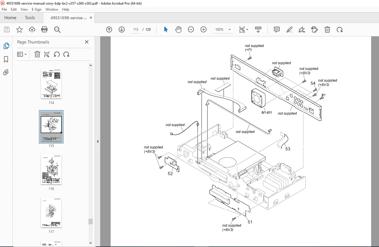
10-1. Exploded Views:
10-1-1. Case Section:
- Upper case parts
- Lower case components
- Screw listings
- Plastic parts identification
- Part numbers for ordering
10-1-2. Front/Rear Chassis Section:
- Front panel assembly
- Rear panel components
- Connector boards
- Shield assemblies
- Mounting brackets
10-1-3. Main Chassis Section:
- Main board mounting
- Power supply mounting
- Drive bay assembly
- Internal shields
- Support brackets
10-1-4. BD Section:
- Blu-ray drive assembly
- Optical pickup unit (KEM-430AAA/C2RP)
- Drive motors
- Drive belts (if applicable)
- Laser assembly
- Drive control board
- Mechanical components
10-1-5. Accessories:
- Remote control assembly
- Cables and connectors
- Power cord
- HDMI cable
- Documentation
10-2. Electrical Parts List:
Complete Component Listings by Board:
FL-193 Board Parts:
- Switch assemblies
- LEDs
- Resistors
- Capacitors
- Connectors
FR-301 Board Parts:
- Drive control ICs
- Motor drivers
- Sensors
- Passive components
- Connectors
MB-127 Main Board Parts:
- Processor IC
- Memory ICs
- HDMI transmitter IC
- Audio/video DACs
- Power management ICs
- Voltage regulators
- Inductors and transformers
- Capacitors (all values)
- Resistors (all values)
- Diodes and transistors
- Connectors
- Crystal oscillators
- Filters
USB-014 Board Parts:
- USB connectors
- Protection components
- Passive components
Power Supply Parts:
- Switching regulators
- Transformers
- Rectifiers
- Filter capacitors
- Protection components
Parts Information Includes:
- Sony part numbers
- Component values
- Component ratings
- Reference designators
- Substitute part information
- Ordering information
- Critical vs. standard parts identification
KEY FEATURES OF SONY BDP PLAYERS:
Blu-ray Disc Technology: ✓ High Definition Video – 1080p playback capability
✓ Advanced Audio – Dolby TrueHD, DTS-HD Master Audio
✓ BD-Live Support – Network interactive features
✓ Bonus View – Picture-in-picture commentary
✓ DVD Upscaling – Enhanced DVD playback
✓ CD Playback – Audio CD support
Connectivity: ✓ HDMI Output – Digital video and audio
✓ Component Video – High-quality analog video
✓ Composite Video – Standard video output
✓ Optical Digital Audio – S/PDIF output
✓ Coaxial Digital Audio – Alternative digital output
✓ Ethernet Port – Network connectivity
✓ USB Port – External device support
Smart Features: ✓ BD-Live – Internet connectivity for bonus content
✓ Firmware Updates – Via network or USB
✓ DLNA Support – Home network streaming
✓ USB Playback – Photos, music, video files
Who Needs This Manual:
✓ Consumer Electronics Repair Technicians servicing Blu-ray players
✓ Home Theater Installation Specialists performing advanced troubleshooting
✓ Electronic Service Centers repairing Sony equipment
✓ Professional AV Technicians maintaining home theater systems
✓ Electronics Hobbyists with advanced repair skills
✓ Technical Training Schools teaching consumer electronics repair
✓ Warranty Repair Centers authorized for Sony service
✓ Independent Repair Shops expanding service capabilities
✓ Parts Suppliers identifying correct replacement components
✓ DIY Enthusiasts tackling complex repairs
What Makes This Manual Essential:
- Official Sony factory documentation – Authorized service information
- Four model coverage – BX2, S357, S360, S363 in one manual
- 129 comprehensive pages – Complete technical information
- 18 detailed schematics – Full circuit diagrams
- Complete PCB layouts – Component-level repair capability
- Service mode instructions – Advanced diagnostics and adjustments
- Error code reference – Complete troubleshooting guide
- Exploded view diagrams – Parts identification and ordering
- IC pin functions – Detailed component information
- Safety compliance – Proper procedures and warnings
- Multi-region coverage – All voltage and regional variants
Critical Service Information:
Optical Drive Service:
- KEM-430AAA/C2RP optical pickup specifications
- Laser safety protocols
- Drive data decode procedures
- Barcode system for replacement authentication
- BU (optical block) repair guidelines
- Adjustment and calibration procedures
Software Requirements:
- Microsoft .NET Framework 2.0 installation
- Service Pack 1 for .NET Framework
- BDBUDec decode software operation
- Password-protected security system
- Online service tool downloads
Test Equipment:
- Required test discs (Blu-ray, DVD, CD)
- Oscilloscope for waveform verification
- Multimeter for voltage testing
- AC leakage tester for safety verification
- HDMI analyzer (recommended)
- Signal generator for alignment
Safety Compliance:
- CLASS 1 LASER PRODUCT certification
- AC leakage testing mandatory after repair
- Safety-related component identification
- Must use Sony genuine parts for critical components
- Unleaded solder specifications and procedures
Troubleshooting Coverage:
Common Problems Addressed:
- Disc not recognized or won’t play
- Tray won’t open/close (includes forced ejection)
- No picture or sound output
- HDMI connection issues
- Network connectivity problems
- USB device not recognized
- Remote control not responding
- Error messages and codes
- Intermittent operation
- Power supply failures
Diagnostic Procedures:
- Systematic approach to fault isolation
- Decision trees for efficient diagnosis
- Test point measurements
- Waveform analysis
- Component testing procedures
- Board-level troubleshooting
Professional Blu-ray player service resource! This official Sony BDP-BX2/S357/S360/S363 service manual is absolutely essential for anyone servicing these popular Blu-ray players. Download instantly and access complete factory schematics, detailed PCB layouts, service mode instructions, error code reference, and comprehensive troubleshooting procedures. Repair with confidence using genuine Sony specifications, proper optical drive replacement procedures, and safety-compliant service methods. Perfect for consumer electronics technicians, home theater specialists, and advanced DIY repair enthusiasts requiring professional-grade technical documentation!
Pricing Rationale:
- Official Sony factory service manual (129 pages)
- Covers four popular Blu-ray player models
- Complete schematics and PCB layouts for component-level repair
- Service mode access and advanced diagnostics
- Multi-region coverage (all voltage variants)
- Target audience: consumer electronics technicians, AV specialists
- Essential for out-of-warranty repairs
- Competitive with other consumer electronics service manuals
- High-value content including optical drive service procedures
- Professional-grade technical documentation