Sony DSR-PD175P PD177P PD198P Service Manual PDF
Original price was: $95.00.$18.95Current price is: $18.95.
Complete factory service manual for Sony DSR-PD175P, DSR-PD177P, and DSR-PD198P professional DVCAM camcorders. Comprehensive 249-page technical manual covering AEP, E, and Chinese models with MDX-N221 mechanism. Includes specifications, block diagrams, schematic diagrams, disassembly procedures, adjustments, repair parts list, and printed wiring boards. Essential for video equipment technicians servicing Sony’s professional 3-CMOS DVCAM camcorders with 20x optical zoom and XLR audio inputs.
Description
Sony DSR-PD175P PD177P PD198P Service Manual DVCAM Camcorder Repair Guide PDF DOWNLOAD
DESCRIPTION
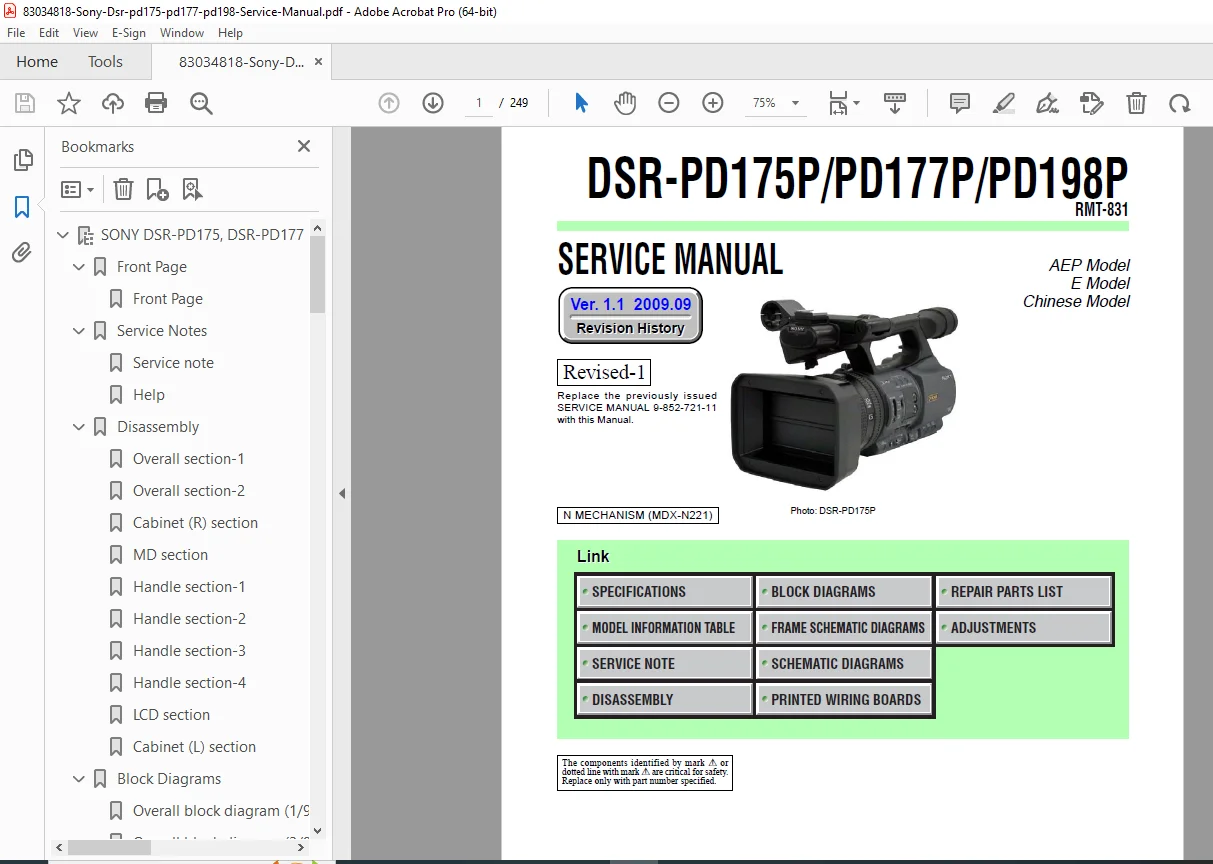
Sony DSR-PD175P/PD177P/PD198P DVCAM Camcorder – Complete Service Manual
This comprehensive Sony DVCAM professional camcorder service manual provides complete technical documentation for servicing the DSR-PD175P, DSR-PD177P, and DSR-PD198P models. Essential reference for professional video equipment technicians, broadcast engineers, and camcorder repair specialists.
📋 FILE DETAILS
- Manual Name: DSR-PD175P/PD177P/PD198P Service Manual
- Document Number: 9-852-721-12
- Version: 1.1 (September 2009)
- Equipment Type: Professional DVCAM Digital Camcorder
- Manufacturer: Sony Corporation (Sony EMCS Co.)
- Models Covered:
- DSR-PD175P (AEP Model)
- DSR-PD177P (E Model)
- DSR-PD198P (Chinese Model)
- Remote Control: RMT-831
- Mechanism: MDX-N221 (N Mechanism)
- Publication Date: 2009 (Published by Tokai TEC)
- Pages: 249 pages
- PDF Quality: High-quality factory original documentation
- File Size: 21.6 MB
- Replaces: Previous Service Manual 9-852-721-11
🎥 CAMCORDER OVERVIEW
Sony DSR-PD175P/PD177P/PD198P Professional DVCAM Camcorder
Professional-grade video camcorder featuring:
Recording Format:
- DVCAM – Professional digital video format
- DV – Consumer DV format compatibility
- Switchable recording modes
Image Sensor:
- 3-CMOS System – 1/3-inch type (6.0mm) sensors
- Separate sensors for Red, Green, Blue
- ClearVid CMOS technology
- Gross: Approx. 1,120,000 pixels per sensor
- Effective pixels (16:9 movie): Approx. 1,037,000 pixels
- Effective pixels (4:3 movie): Approx. 778,000 pixels
- Still image capability: Max 1.20 Megapixels (1440 × 810)
Lens System:
- Sony G Lens – Professional optics
- 20x Optical Zoom (f=4.1-82.0mm)
- Approx. 30x Digital zoom (with D.EXTENDER on)
- 35mm equivalent: 29.5-590mm (16:9), 36.1-722mm (4:3)
- Aperture: F1.6-3.4
- 72mm filter diameter
Viewfinder & LCD:
- Electric color/B&W viewfinder
- 0.45-inch type (16:9 aspect ratio)
- Total dots: 1,226,880 (852 × 3[RGB] × 480)
- 3.2-inch LCD screen (16:9 aspect ratio)
- Total dots: 921,600 (1920 × 480)
🔧 MANUAL SECTIONS & CONTENTS
SECTION 1: SPECIFICATIONS
Recording System:
- Video: 2 rotary heads, helical scanning (DVCAM/DV)
- Audio: Rotary heads, PCM system
- 12-bit quantization, 32kHz sampling (stereo channels 1/2)
- 16-bit quantization, 48kHz sampling (stereo channels 1/2)
- Still image: Exif Ver. 2.2 format
Video Signal:
- PAL color, CCIR standards
Tape Specifications:
- Mini DV cassettes
- Mini DVCAM cassettes
- DVCAM tape speed: 28.221 mm/s
- DV SP tape speed: 18.831 mm/s
- DVCAM recording time: 41 min (PDVM-40ME cassette)
- DV SP recording time: 63 min (PDVM-40ME cassette)
Performance Specifications:
- Minimum illumination: 1.5 lux (1/25 shutter, auto gain, F1.6)
- White balance: AUTO, Indoor (3200K), Outdoor (5800K), Manual (2300K-15000K in 100K steps)
Power & Dimensions:
- DC 7.2V (battery pack) / DC 8.4V (AC adaptor)
- DVCAM recording consumption: 6.0W (viewfinder), 6.2W (LCD)
- Operating temperature: 0°C to 40°C (32°F to 104°F)
- Dimensions: 169 × 188 × 401mm (w/h/d) including projecting parts
- Mass: Approx. 2.2 kg (4 lb 14 oz) with lens hood
Professional Connectors:
- XLR Audio Inputs – INPUT1/INPUT2 (3-pin female)
- -48 dBu: 3kΩ impedance
- +4 dBu: 10kΩ impedance
- DV/i.LINK – IEEE 1394 (4-pin S100)
- LANC Jack – Stereo mini-minijack (2.5mm)
- A/V Remote – 10-pin connector
- Headphone Jack – Stereo minijack (3.5mm)
SECTION 2: BLOCK DIAGRAMS
- Complete system block diagrams
- Signal flow illustrations
- Board interconnections
- Power distribution diagrams
- Audio/video signal paths
- Mechanism control systems
SECTION 3: MODEL INFORMATION TABLE
- DSR-PD175P – AEP Model specifications
- DSR-PD177P – E Model specifications
- DSR-PD198P – Chinese Model specifications
- Regional differences and configurations
- Model-specific components
SECTION 4: SERVICE NOTE
Critical Service Procedures:
4-1. Power Supply During Repairs:
- Special power-up sequence (10-second auto-shutoff)
- Method: Use AC adaptor (AC-L100/L100C) for bench testing
- Regulated power supply limitations
4-2. Force Eject Procedure:
- Emergency cassette removal when eject fails
- CS lid (93501) assembly removal
- Loading motor manual operation (+4.5V DC power supply)
4-3. Forced Power ON Mode:
- Adjustment remote commander operation (RM-95 or NEW LANC JIG)
- Forced Camera Power ON: Page 0, Address 01, Data 01
- Forced VTR Power ON: Page A, Address 10, Data 02
- Exit procedures
4-4. Service Jig Usage:
- CPC-13 jig (J-6082-443-A) connection to CN1004 on VC-597 board
- Pin assignments and signal names
- Test point access
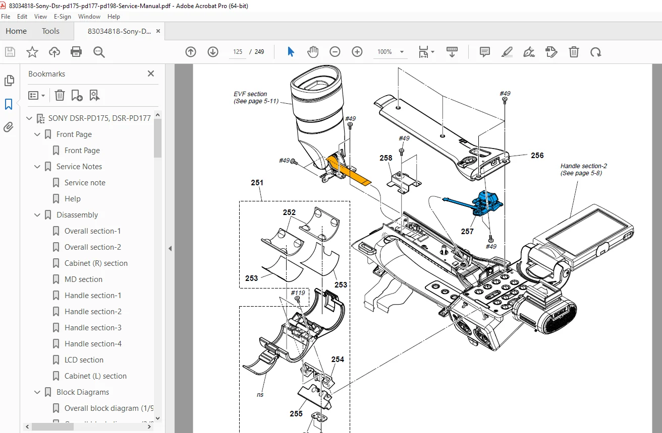
SECTION 5: DISASSEMBLY
- Complete step-by-step disassembly procedures
- Exploded view diagrams
- Screw location maps
- Component removal sequences
- Mechanism disassembly (MDX-N221)
- Lens assembly removal
- CRT board access
- Circuit board removal procedures
- Reassembly notes and precautions
SECTION 6: ADJUSTMENTS
- White balance calibration
- Black balance adjustment
- Back focus alignment
- Lens optical adjustments
- Viewfinder alignment
- LCD calibration
- Audio level adjustments
- Mechanism timing adjustments
- Tape tension adjustments
- Test equipment requirements
- Adjustment remote commander procedures
SECTION 7: FRAME SCHEMATIC DIAGRAMS
- Mechanical frame assembly diagrams
- Structural component relationships
- Mounting points and hardware
- Chassis layout views
SECTION 8: SCHEMATIC DIAGRAMS
Complete Circuit Schematics:
- Power supply circuits
- Camera processing boards
- Signal processing circuits
- Audio amplifier circuits
- Mechanism control circuits
- LCD/Viewfinder driver circuits
- Interface circuits (DV, LANC, XLR)
- Sensor processing circuits (3-CMOS)
Safety-Critical Components:
- Components marked with “0” or dotted line with “0”
- Must be replaced with specified Sony part numbers only
- Safety check-out procedures after repair
SECTION 9: PRINTED WIRING BOARDS
- Component-side PCB layouts
- Solder-side PCB layouts
- Component location diagrams
- Test point locations
- Board interconnection points
- Signal trace identification
- IC pinout references
SECTION 10: REPAIR PARTS LIST
- Complete parts catalog with Sony part numbers
- Board-specific component listings
- Mechanical parts and hardware
- Optical components and lens elements
- Tape mechanism parts (MDX-N221)
- Electrical components with specifications
- Model-specific part variations
- Critical safety components identification
⚙️ KEY TECHNICAL FEATURES
DVCAM Professional Format:
- Superior to consumer DV format
- Wider track pitch for reliable recording
- Professional audio quality (16-bit/48kHz)
- Frame-accurate editing capability
- Broadcast-quality video
3-CMOS Imaging System:
- True three-chip color separation
- Superior color reproduction vs single-chip
- Enhanced low-light performance
- Reduced moiré and aliasing
- Professional image quality
Professional Audio:
- Balanced XLR inputs (2 channels)
- Phantom power support
- Manual audio level control
- 16-bit/48kHz professional PCM recording
- External microphone support
Enhanced Imaging Processor:
- Sony’s proprietary image processing
- ClearVid CMOS technology
- Advanced noise reduction
- Superior dynamic range
🎯 IDEAL FOR
- Professional video equipment technicians
- Broadcast facility service engineers
- Production company maintenance staff
- Sony authorized service centers
- Independent camcorder repair specialists
- Video production rental houses
- Educational institution A/V departments
- Corporate video department technicians
- Wedding/event videography businesses
- Government/military video equipment maintenance
⚠️ SAFETY & SERVICE REQUIREMENTS
Safety-Critical Components: Components identified by mark “0” or dotted line with “0” are critical for safety. Replace only with specified Sony part numbers.
Safety Check-Out Procedures:
- Inspect for unsoldered/poorly-soldered connections
- Check for solder splashes and bridges
- Verify interboard wiring (no pinched wires)
- Check for unauthorized replacement parts
- Inspect for deteriorated components
- Verify B+ voltage specifications
Lead-Free Solder Requirements:
- Boards marked with LF symbol use unleaded solder
- Melting point approximately 40°C higher than ordinary solder
- Soldering iron temperature: ~350°C (regulated)
- Stronger viscosity – watch for solder bridges
- Can be mixed with ordinary solder if necessary
Flexible Circuit Board Repair:
- Soldering iron temperature: ~270°C
- Maximum 3 touches per conductor
- Avoid applying force during soldering
Battery Safety:
- Explosion danger if incorrectly replaced
- Replace only with same or equivalent type
- Proper disposal procedures required
💡 WHY THIS MANUAL IS ESSENTIAL
Professional DVCAM Equipment: The DSR-PD175P/PD177P/PD198P represents Sony’s professional DVCAM line requiring specialized service knowledge beyond consumer camcorders.
Complex Systems: ✓ 3-CMOS imaging system with precise alignment requirements ✓ Professional audio circuits with balanced XLR inputs ✓ DVCAM mechanism with different tape speed than DV ✓ Advanced signal processing with Enhanced Imaging Processor ✓ Professional lens assembly with 20x optical zoom ✓ Multiple recording formats and modes
Service-Specific Features: ✓ Forced power-on modes for bench testing ✓ Force eject procedures for mechanism failures ✓ Service jig connections and test points ✓ Adjustment remote commander procedures ✓ Model-specific variations (AEP, E, Chinese)
Complete Documentation: Unlike basic user manuals, this factory service manual provides component-level schematics, adjustment procedures, and exact Sony part numbers essential for professional repair.
🔍 INCLUDED ACCESSORIES
AC Adaptor AC-L100/AC-L100C:
- Input: AC 100V-240V, 50/60Hz
- Output: DC 8.4V
- Power consumption: 18W
- Dimensions: 48 × 29 × 81mm (w/h/d)
- Mass: Approx. 170g
🚀 Download instantly and service professional DVCAM equipment! Stop struggling with professional Sony camcorder repairs without proper documentation. This factory-authorized service manual provides the exact specifications, procedures, and part numbers needed to service DSR-PD175P/PD177P/PD198P DVCAM camcorders professionally. Essential for anyone maintaining Sony’s professional video production equipment with 3-CMOS sensors, XLR audio inputs, and DVCAM recording capability.
Pricing rationale:
- 249 pages of comprehensive technical content
- Covers three professional DVCAM camcorder models
- Sony factory-authorized documentation (2009 edition)
- Includes MDX-N221 mechanism documentation
- Professional/broadcast equipment (not consumer)
- 3-CMOS imaging system technical details
- Complete schematic diagrams and PCB layouts
- Professional XLR audio circuit documentation
- Essential for servicing $2,000-4,000 professional camcorders
- Still widely used in professional video production
- Includes adjustment procedures with remote commander
- Service jig specifications and force eject procedures
- Lead-free solder repair guidelines