Sony DVP-S735D Service Manual PDF Download
Original price was: $95.00.$15.95Current price is: $15.95.
Download the official Sony DVP-S735D service manual PDF for CD/DVD player repair and troubleshooting. This Sony DVD player repair guide covers models DVP-S335, S336, S345, S535D, S735D with disassembly instructions, block diagrams, schematic diagrams, and electrical adjustments in the DVP-S735D schematic diagrams PDF. Perfect for technicians performing Sony CD DVD player maintenance.
Description
Sony DVP-S735D Service Manual PDF Download
Description
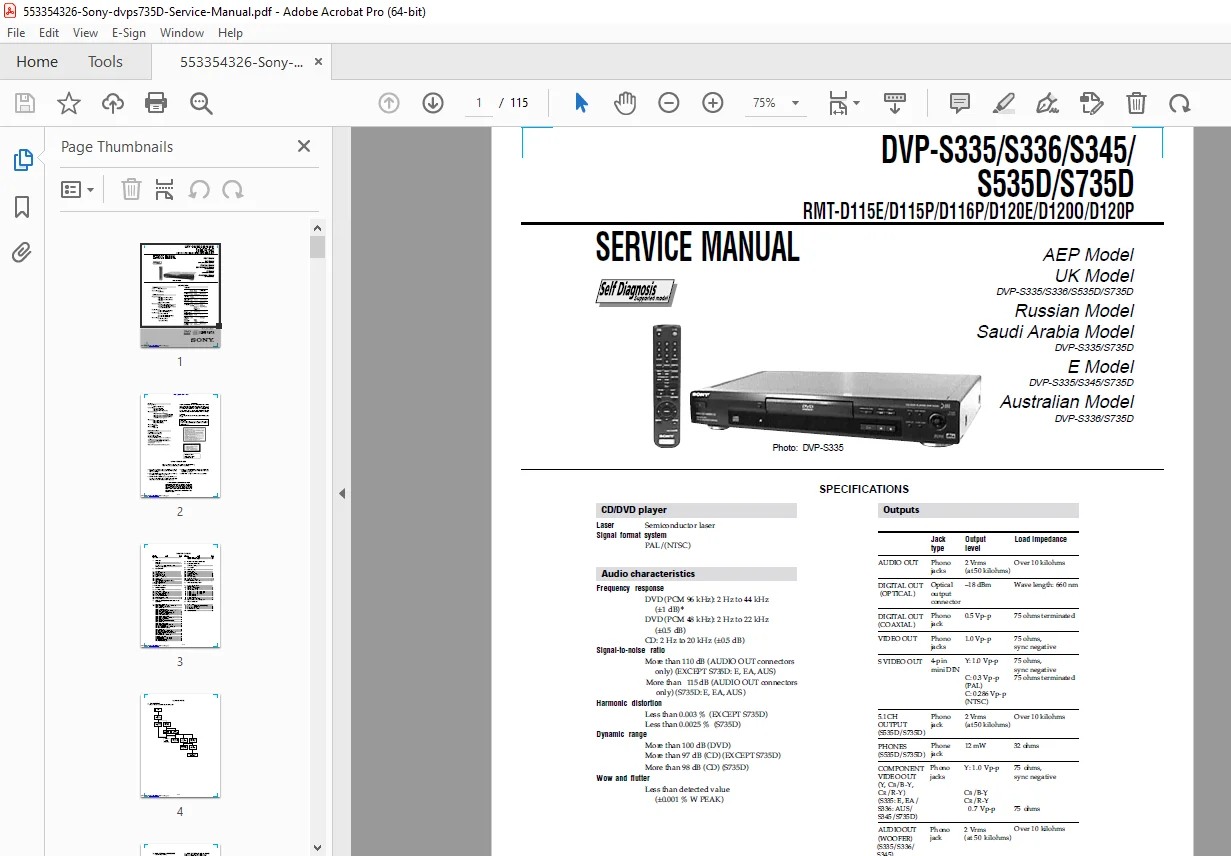
The Sony DVP-S735D Service Manual PDF Download is a complete technical resource for servicing Sony CD/DVD players, including models DVP-S335, S336, S345, S535D, and S735D across various regions like AEP, UK, Russian, Saudi Arabia, E, and Australian. This Sony DVD player repair guide details specifications, disassembly procedures, block diagrams, printed wiring boards, schematic diagrams, test modes, electrical adjustments, and repair parts lists, making it essential for efficient Sony CD DVD player maintenance and diagnostics.
File Details:
- Manual Name: Service Manual for DVP-S335/S336/S345/S535D/S735D CD/DVD Player
- Models Covered: DVP-S335, S336, S345, S535D, S735D
- Year: 2000 (approximate, based on model release)
- Manual PDF Quality: High-quality scanned document
- No. of Pages: 115
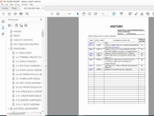
The manual includes safety warnings, laser precautions, and self-diagnosis features. Below is the neatly categorized Table of Contents extracted from the manual:
- Service Note (Page 4)
- Section 1: GENERAL
- Getting Started (Page 1-1)
- Playing Discs (Page 1-4)
- Using Various Functions with the Control Menu (Page 1-6)
- Settings and Adjustments (Page 1-11)
- Section 2: DISASSEMBLY
- 2-1. Case Removal (Page 2-1)
- 2-2. Rear Panel Removal (Page 2-1)
- 2-3. Tray Cover Removal (Page 2-1)
- 2-4. Front Panel Removal (Page 2-1)
- 2-5. Power Block Removal (Page 2-2)
- 2-6. Mechanism Deck Removal (Page 2-2)
- 2-7. Tray Removal (Page 2-2)
- 2-8. Optical Pick-up Removal (Page 2-2)
- 2-9. Belt, MB-86 Board, Loading Motor (M001), MS-48 Board Removal (Page 2-3)
- 2-10. AI-17 Board Removal (Page 2-3)
- 2-11. Internal Views (Page 2-4)
- 2-12. Circuit Boards Location (Page 2-5)
- Section 3: BLOCK DIAGRAMS
- 3-1. Overall Block Diagram (Page 3-1)
- 3-2. RF/Servo Block Diagram (Page 3-3)
- 3-3. Signal Processor Block Diagram (Page 3-5)
- 3-4. System Control Block Diagram (Page 3-7)
- 3-5. Audio (1) Block Diagram (Page 3-9)
- 3-6. Video/Audio (2) Block Diagram (Page 3-11)
- 3-7. Interface Control Block Diagram (Page 3-13)
- 3-8. Power Block Diagram (Page 3-15)
- Section 4: PRINTED WIRING BOARDS AND SCHEMATIC DIAGRAMS
- 4-1. Frame Schematic Diagrams (Page 4-3)
- 4-2. Printed Wiring Boards and Schematic Diagrams (Page 4-5)
- MS-48 Printed Wiring Board and Schematic Diagram (Page 4-5)
- MB-86 Printed Wiring Board (Page 4-7)
- MB-86 (RF AMP, SERVO) Schematic Diagram (Page 4-11)
- MB-86 (ARP) Schematic Diagram (Page 4-13)
- MB-86 (AV DECODER) Schematic Diagram (Page 4-15)
- MB-86 (SDRAM) Schematic Diagram (Page 4-17)
- MB-86 (VGA) Schematic Diagram (Page 4-19)
- MB-86 (DRIVE) Schematic Diagram (Page 4-21)
- MB-86 (SERVO DSP) Schematic Diagram (Page 4-22)
- MB-86 (SYSTEM CONTROL) Schematic Diagram (Page 4-25)
- MB-86 (MEMORY, CLOCK GENERATOR) Schematic Diagram (Page 4-27)
- MB-86 (FGA) Schematic Diagram (Page 4-29)
- MB-86 (AUDIO DSP) Schematic Diagram (Page 4-31)
- AI-17 Printed Wiring Board (Page 4-33)
- AI-17 (VIDEO BUFFER) Schematic Diagram (Page 4-35)
- AI-17 (D/A CONVERTER, DSP) Schematic Diagram (Page 4-37)
- AI-17 (AMP, LPF) Schematic Diagram (Page 4-39)
- AI-17 (D/A CONVERTER) Schematic Diagram (Page 4-41)
- AI-17 (MODE CONTROL, POWER SUPPLY) Schematic Diagram (Page 4-43)
- AI-17 (IF CON) Schematic Diagram (Page 4-45)
- ER-9 Printed Wiring Board (Page 4-47)
- ER-9 (EURO AV1) Schematic Diagram (Page 4-51)
- ER-9 (EURO AV2) Schematic Diagram (Page 4-53)
- HP-127 Printed Wiring Board (Page 4-56)
- HP-127 Schematic Diagram (Page 4-57)
- HS16S9E Printed Wiring Board (Page 4-59)
- HS16S9E Schematic Diagram (Page 4-61)
- Section 5: IC PIN FUNCTION DESCRIPTION
- 5-1. System Control Pin Function (MB-86 Board IC102) (Page 5-1)
- Section 6: TEST MODE
- 6-1. General Description (Page 6-1)
- 6-2. Starting Test Mode (Page 6-1)
- 6-3. Syscon Diagnosis (Page 6-1)
- 6-4. Drive Auto Adjustment (Page 6-5)
- 6-5. Drive Manual Operation (Page 6-7)
- 6-6. Mecha Aging (Page 6-9)
- 6-7. Emergency History (Page 6-9)
- 6-8. Version Information (Page 6-10)
- 6-9. Video Level Adjustment (Page 6-10)
- 6-10. If Con Self Diagnostic Function (Page 6-11)
- Section 7: ELECTRICAL ADJUSTMENT
- 7-1. Power Supply Adjustment (Page 7-1)
- 7-2. Adjustment of Video System (Page 7-2)
- 7-3. Adjustment Related Parts Arrangement (Page 7-6)
- Section 8: REPAIR PARTS LIST
- 8-1. Exploded Views (Page 8-1)
- 8-1-1. Case Assembly (S335/S336/S345/S535D) (Page 8-1)
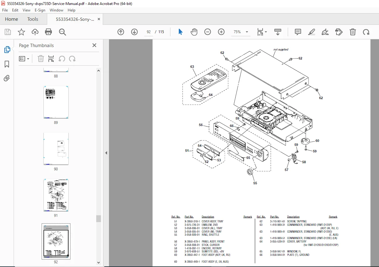
- 8-1-2. Case Assembly (S735D) (Page 8-2)
- 8-1-3. Chassis Assembly (Page 8-3)
- 8-1-4. Mechanism Deck Section (Page 8-5)
- 8-2. Electrical Parts List (Page 8-6)
- 8-1. Exploded Views (Page 8-1)
This DVP-S735D schematic diagrams PDF supports troubleshooting with detailed waveforms, IC pin functions, and exploded views for precise Sony CD DVD player maintenance. No index is present, but the TOC provides excellent navigation.
Revive your vintage Sony player—download this Sony DVP-S735D service manual PDF instantly for expert repairs and reliable performance!