Sony Hdr fx1 Level3 Ver1 3 Hd Video Camera Service Manual – PDF Download
Original price was: $34.95.$19.95Current price is: $19.95.
Sony Hdr fx1 Level3 Ver1 3 Hd Video Camera Service Manual
Description
Sony Hdr fx1 Level3 Ver1 3 Hd Video Camera Service Manual
FILE DETAILS:
Sony Hdr fx1 Level3 Ver1 3 Hd Video Camera Service Manual
LANGUAGE:ENGLISH
PAGES:95
DOWNLOADABLE:YES
FILE TYPE:PDF
SONY HDR FX1 LEVEL3 VER1 3 HD VIDEO CAMERA SERVICE MANUAL – PDF DOWNLOAD:
IMAGES PREVIEW OF THE MANUAL:
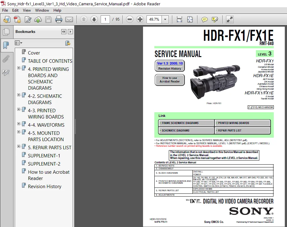
SAMPLE PAGE FROM THE MANUAL:
Sony Hdr fx1 Level3 Ver1 3 Hd Video Camera Service Manual
1. Check the area of your repair for unsoldered or poorly-soldered connections. Check the entire board surface for solder splashes and bridges.
2. Check the interboard wiring to ensure that no wires are “pinched” or contact high-wattage resistors.
3. Look for unauthorized replacement parts, particularly transistors, that were installed during a previous repair. Point them out to the customer and recommend their replacement.
4. Look for parts which, through functioning, show obvious signs of deterioration. Point them out to the customer and recommend their replacement.
5. Check the B+ voltage to see it is at the values specified.
6. Flexible Circuit Board Repairing
• Keep the temperature of the soldering iron around 270°C during repairing.
• Do not touch the soldering iron on the same conductor of the circuit board (within 3 times).
• Be careful not to apply force on the conductor when soldering or unsoldering.
TABLE OF CONTENTS:
Sony Hdr fx1 Level3 Ver1 3 Hd Video Camera Service Manual
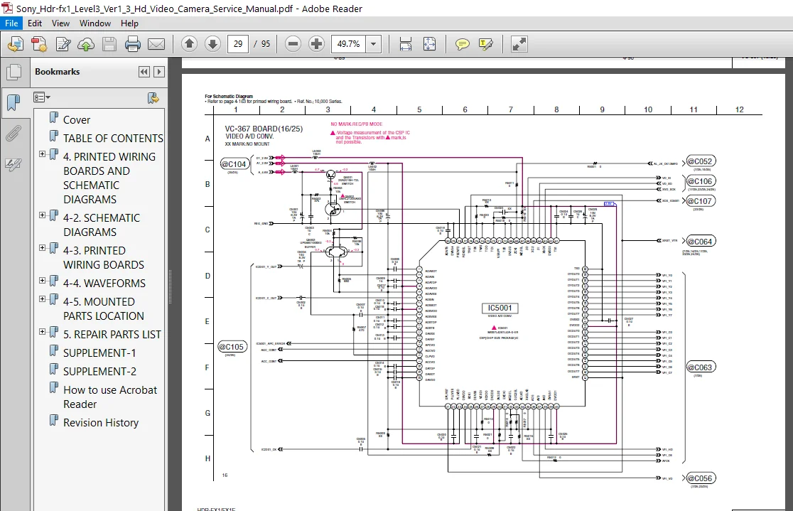
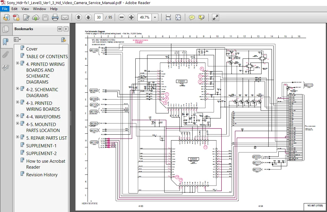
Cover.............................................. 1
TABLE OF CONTENTS.................................. 4
4. PRINTED WIRING BOARDS AND SCHEMATIC DIAGRAMS.... 5
	4-1. FRAME SCHEMATIC DIAGRAM (1/2)............. 5
		FRAME SCHEMATIC DIAGRAM (2/2).............. 6
4-2. SCHEMATIC DIAGRAMS............................ 7
	CD-522.........................................10
	DA-033.........................................11
	DB-018 (1/2)...................................12
	DB-018 (2/2)...................................13
	VC-367 (1/25)..................................14
	VC-367 (2/25)..................................15
	VC-367 (3/25)..................................16
	VC-367 (4/25)..................................17
	VC-367 (5/25)..................................18
	VC-367 (6/25)..................................19
	VC-367 (7/25)..................................20
	VC-367 (8/25)..................................21
	VC-367 (9/25)..................................22
	VC-367 (10/25).................................23
	VC-367 (11/25).................................24
	VC-367 (12/25).................................25
	VC-367 (13/25).................................26
	VC-367 (14/25).................................27
	VC-367 (15/25).................................28
	VC-367 (16/25).................................29
	VC-367 (17/25).................................30
	VC-367 (18/25).................................31
	VC-367 (19/25).................................32
	VC-367 (20/25).................................33
	VC-367 (21/25).................................34
	VC-367 (22/25).................................35
	VC-367 (23/25).................................36
	VC-367 (24/25).................................37
	VC-367 (25/25).................................38
4-3. PRINTED WIRING BOARDS.........................39
	CD-522.........................................42
	DA-033.........................................44
	DB-018.........................................46
	VC-367.........................................48
4-4. WAVEFORMS.....................................50
	CD-522.........................................50
	VC-367.........................................51
4-5. MOUNTED PARTS LOCATION........................52
	CD-522.........................................52
	DA-033.........................................52
	DB-018.........................................53
	VC-367.........................................54
5. REPAIR PARTS LIST...............................57
	5-2. ELECTRICAL PARTS LIST.....................58
		CD-522.....................................58
		DA-033.....................................59
		DB-018.....................................61
		VC-367.....................................63
SUPPLEMENT-1.......................................78
SUPPLEMENT-2.......................................86
How to use Acrobat Reader..........................93
Revision History...................................95
PLEASE NOTE:
⦁ This is the SAME MANUAL used by the dealerships to diagnose your vehicle
⦁ No waiting for couriers / posts as this is a PDF manual and you can download it within 2 minutes time once you make the payment.
⦁ Your payment is all safe and the delivery of the manual is INSTANT – You will be taken to the DOWNLOAD PAGE.
⦁ So have no hesitations whatsoever and write to us about any queries you may have : heydownloadss @gmail.com