Sony HVR-Z1U Z1J Z1E HDV Professional Video Camera Service Manual PDF
Original price was: $95.00.$18.95Current price is: $18.95.
Official Sony service manual for HVR-Z1 series professional HDV camcorders including Z1U (US/Canadian), Z1E (European), Z1J (Japanese), Z1N, Z1P, and Z1C models. This comprehensive 482-page technical manual provides complete specifications, block diagrams, schematic diagrams, disassembly procedures, adjustment protocols, self-diagnosis codes, and repair parts lists for professional broadcast-quality HDV cameras. Essential reference for professional video camera technicians and broadcast equipment service centers.
Description
Sony HVR-Z1U Z1J Z1E HDV Professional Video Camera Service Manual Repair Guide – PDF DOWNLOAD
DESCRIPTION
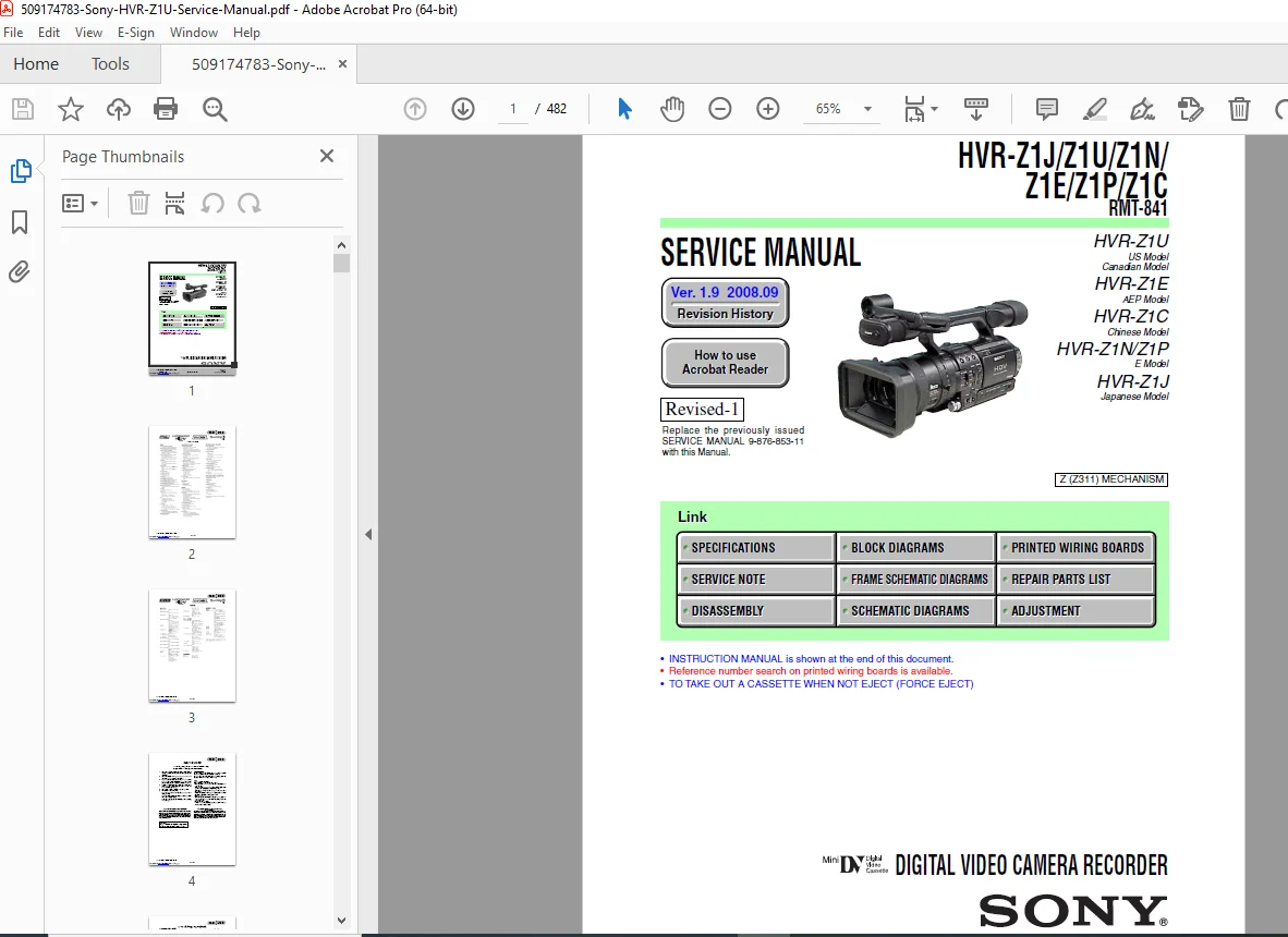
Sony HVR-Z1 Series HDV Professional Camcorder – Complete Service Manual
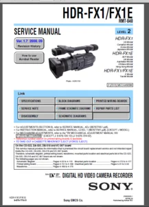
This is the official Sony service manual (Version 1.9, September 2008, Part No. 9-876-853-12) for the HVR-Z1 series professional HDV camcorders, providing comprehensive technical documentation for servicing, troubleshooting, and repairing these broadcast-quality video cameras used by professional videographers, television production crews, and broadcast facilities worldwide.
📋 FILE DETAILS
- Manual Title: HVR-Z1J/Z1U/Z1N/Z1E/Z1P/Z1C Service Manual
- Part Number: 9-876-853-12
- Publication Date: September 2008 (Version 1.9)
- Total Pages: 482 pages
- PDF Quality: High-resolution professional technical manual
- Language: English with Japanese sections
- Manufacturer: Sony EMCS Co.
- Remote Commander: RMT-841 model covered
📹 CAMERA MODELS COVERED
HVR-Z1U:
- US Model and Canadian Model
- NTSC (60i) video system
- Full HDV 1080i recording capability
HVR-Z1E:
- AEP (Asia, Europe, Pacific) Model
- PAL (50i) video system
- HDV 1080i25 recording
HVR-Z1J:
- Japanese Model
- NTSC video system
- Japan market specifications
HVR-Z1N / Z1P:
- E Model variants
- European market configurations
HVR-Z1C:
- Chinese Model
- Market-specific configuration
Common Features All Models:
- HDV 1080i format recording
- 3x 1/3″ ClearVid CMOS Sensor (later models) or 3-CCD system
- Professional Carl Zeiss Vario-Sonnar T* lens
- 12x optical zoom
- DV/HDV switchable recording
- XLR professional audio inputs
- Manual lens control rings
- LANC terminal
- Component video output
- IEEE 1394 (i.LINK/FireWire) interface
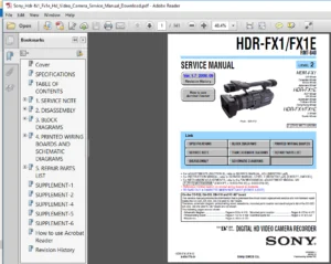
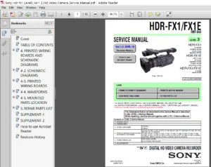
📖 COMPREHENSIVE TABLE OF CONTENTS
Section 1: Service Note (Pages 1-1 to 1-4)
1-1. Service Note:
- Note for repair procedures
- Power supply during repairs (3 methods explained)
- Force eject procedure for cassette removal
- Flat cable and flexible board handling precautions
- Connector installation/removal guidelines
- Unleaded solder characteristics and procedures
1-2. Self-Diagnosis Function:
- Self-diagnosis system overview
- Self-diagnosis display interpretation
- Self-diagnosis code table with detailed fault codes
- Counter display format (alphabet + 4-digit number)
- Troubleshooting using diagnostic codes
Section 2: Disassembly (Pages 2-1 to 2-12)
2-1. Disassembly:
- Step-by-step disassembly procedures
- Component removal sequences
- Safety precautions during disassembly
2-2. Service Position:
- Service mode positioning
- Accessing internal components
2-3. Circuit Boards Location:
- Main board locations and identification
- PCB layout diagrams
2-4. Flexible Boards Location:
- Flexible PCB routing
- Connection point identification
Section 3: Block Diagrams (Pages 3-1 to 3-19)
3-1 to 3-6. Overall Block Diagrams (6 sheets):
- Complete system architecture
- Signal flow diagrams
- Component interconnections
3-7 to 3-10. Power Block Diagrams (4 sheets):
- Power distribution architecture
- DC/DC converter circuits
- Battery charging system
- Power supply regulation
Section 4: Printed Wiring Boards and Schematic Diagrams (Pages 4-1 to 4-173)
4-1. Frame Printed Wiring Board (2 sheets):
- Main board layout diagrams
4-2. Schematic Diagrams:
Complete circuit schematics for all boards including:
- CK-143 – Function Key board
- FP-962 – Iris Dial flexible board
- FP-963 – WB/Gain switch flexible board
- FP-965 – Lid switch flexible board
- FK-090 – VTR Function Key board
- FP-959 – Battery flexible board
- FP-960 – Mic Select flexible board
- FP-961 – Function Key, Tally flexible board
- FP-964 – DV Terminal flexible board
- FP-971/972/974/975/976/977/978/980/981 – Various relay flexible boards
- IF-122 – Relay board
- FP-967 – MR Sensor flexible board
- SW-433 – Panel REV switch
- JK-275 – Jack board
- LB-106 – EVF Backlight board
- MA-431 – Internal Mic Amp board
- MK-017 – Function Key board
- FP-966 – Auto Lock flexible board
- MR-048 (2 sheets) – Rec/PB RF Amp, Drum/Capstan/Loading Motor Drive
- PD-222 – LCD Driver, Timing Generator
- SE-150 – Pitch/Yaw Sensor Amp
- VA-119 (4 sheets) – Audio In/Out, Video In/Out, Y/Pb/Pr Out Amp, XLR Input
- CD-522 – R/G/B-CH CCD Imager, S/H, AGC
- DA-033 – DC/DC Converter
- DB-018 (2 sheets) – DC In, Charge, DC/DC Converter
VC-367 Main Board (25 sheets):
- CCD RF Input circuits
- R/G/B-CH AGC and A/D Converter
- Timing Generator
- Camera RGB Process
- Lens Drive circuits
- Lens Drive Control
- Camera Control
- Base Band Process
- OSD and D3 Filter
- HDV Video Encoder
- 64MBIT SDRAM (L/U)
- HDV Signal/RF Signal Process
- HDV Video Decoder
- 64MBIT Y/C-SDRAM
- i.LINK Interface
- DV/RF Signal Process
- Video A/D Converter
- EVF RGB Driver
- Timing Generator
- HDV Audio Signal Process
- Audio Input Select
- Audio Convertor
- DS Control
- Front Control
- LSI Control
- Mecha Control
- Connector-1 and Connector-2
4-3. Printed Wiring Boards:
- Component layout diagrams for all boards
- Reference designator locations
4-4. Waveforms:
- Test point waveform diagrams
4-5. Mounted Parts Location:
- Physical component positioning
Section 5: Repair Parts List (Pages 5-1 to 5-150+)
5-1. Exploded Views:
- Overall section assembly
- Cabinet (R) sections (2 sheets)
- Cabinet (L) section
- Handle sections (2 sheets)
- LCD section
- EVF (Electronic Viewfinder) section
- Center section
- Main board section (VA, VC, DA, DB)
- Lens section
- Terminal cabinet section
- Battery section and DV section
- Mechanism deck overall (Z311)
- LS chassis block assembly
- Mechanical chassis block assembly
- Supplied accessories checklist
5-2. Electrical Parts List:
- Complete parts catalog with part numbers
- Component specifications
- Replacement part cross-references
Section 6: Adjustment (Pages 6-1 to 6-139)
6-1. Camera Section Adjustment:
Preparations:
- Service tools list required
- Preparation procedures
- Precautions and safety measures
- Switch settings
- Adjustment order flowchart
- Test subjects and charts required
Initialization Procedures:
- 8, 9, A, B, C, D, E, F, 13, 14, 18, 19, 1A, 1B, 1C, 1D, 1E, 1F page data initialization
- Data modification procedures
- Complete page tables for all memory addresses
Camera System Adjustments (NTSC 60i and PAL 50i modes):
- Origin Oscillation Check
- HALL Adjustment
- MR Adjustment
- Focus Ring Adjustment
- Zoom Ring Adjustment (2 methods)
- Flange Back Adjustment (multiple methods)
- Flange Back Check
- Picture Frame Setting
- Auto White Balance Standard Data Input (ND OFF, ND1, ND2)
- MAX GAIN Adjustment
- LV Standard Data Input
- Auto White Balance Adjustment (ND OFF, ND1, ND2)
- Color Reproduction Adjustment (ND OFF, ND1, ND2)
- White Balance Check (ND OFF, ND1, ND2)
- Color Reproduction Check HD STD γ (ND OFF, ND1, ND2)
- Color Reproduction Check HD CINE γ (ND OFF, ND1, ND2)
- Color Reproduction Check SD STD γ (ND OFF, ND1, ND2)
- Color Reproduction Check SD CINE γ (ND OFF, ND1, ND2)
- PSD Sensor Gain Adjustment
- Angular Velocity Sensor Sensitivity Adjustment
6-1-4. Color Electronic Viewfinder System Adjustment:
- VCO Adjustment
- Backlight Adjustment
- PSIG Level Adjustment
- VCOM Level Adjustment
- RGB AMP Adjustment
- Contrast Adjustment
- White Balance Adjustment
6-1-5. LCD System Adjustment:
- LCD Automatic Adjustment
- Contrast Adjustment (HD)
- V COM Adjustment
- Sample Hold Phase Adjustment
- Transmissive Mode White Balance Adjustment
- Reflective Mode White Balance Adjustment
6-2. Mechanism Section Adjustment:
Preparations and Maintenance:
- Cassette compartment assembly procedures
- Damper assembly service
- Rotary drum cleaning
- Tape path system cleaning
- Periodic inspection list
- Mode Selector II operating procedures
Mechanical Parts Check/Adjustment/Replacement:
- Flowchart for mechanical parts replacement
- Drum assembly service
- Cassette compartment assembly
- Motor holder block assembly
- MIC terminal service
- LED replacement
- Retainer plate service
- Reel table assemblies
- Brake and release rack
- Band adjuster service
- ULE brake assembly
- Cassette positioning
- Pinch arm assembly
- Gooseneck gear assembly
- LS guide components
- Chassis block assemblies
- END/TOP sensors
- Reel sensors
- Guide rail service
- Conversion gear
- Coaster block assemblies
- TG5 roller assembly
- Cam plate assemblies
- LS arm assembly
- M slider assemblies
- EJ arm service
- Cam gear and GL driving
- Rotary encoder
- Flexible board replacements
Adjustments:
- FWD position adjustment
- Reel torque check
- LS cam plate position adjustment
- Tape path adjustment
6-3. Video Section Adjustment:
Preparations:
- Required equipment list
- Adjustment precautions
- Connector identification
- Equipment connections
- Alignment tape specifications
- Input/output level and impedance specifications
System Control System Adjustment:
- Memory page data initialization
- Serial number input procedures
Servo and RF System Adjustment:
- Cap FG Duty Adjustment
- Switching Position Adjustment
- Error Rate Check procedures
Video System Adjustments:
- S VIDEO OUT Y Level Adjustment
- S VIDEO OUT Chroma Level Adjustment
- VIDEO OUT Y, Chroma Level Check
- COMPONENT OUTPUT Level Adjustment
Audio System Adjustments:
- Playback Level Check
- Overall Level Characteristics Check
- Camera E-E Audio Level Check (1) and (2)
6-4. Service Mode:
- Adjustment remote commander usage (RM-95)
- Data process procedures
- Test mode settings
- Emergency memory addresses
- EMG code and MSW code tables
- Bit value discrimination
- Switch checks (5 different tests)
- LED check procedures
- Record of use checks
- Self-diagnosis record check
- Complete self-diagnosis code table
- Color reproduction frame references
🔧 KEY SYSTEMS COVERED
HDV Recording System:
- MPEG-2 video compression
- HDV 1080i format (1920×1080)
- DV format compatibility
- Tape transport mechanism (Z311)
- Drum assembly and head configuration
- RF signal processing
- Servo control system
3-CCD/CMOS Imaging System:
- R/G/B channel CCD imagers
- Sample & Hold circuits
- AGC (Automatic Gain Control)
- A/D conversion
- RGB processing
- Color reproduction matrices
- Gamma correction (STD and CINE modes)
Lens Control System:
- Carl Zeiss lens interface
- Focus ring control
- Zoom ring control
- Iris dial control
- Flange back adjustment
- Lens drive motors
- Position sensors
Audio System:
- XLR professional inputs
- Internal microphone amplifier
- Phantom power (+48V)
- Audio A/D conversion
- HDV audio encoding
- Multi-channel audio processing
Display Systems:
- Electronic Viewfinder (EVF) with RGB driver
- LCD panel with timing generator
- Backlight control
- Contrast and white balance adjustment
- Both transmissive and reflective modes
Power Management:
- Battery charging system
- DC/DC converters (multiple voltages)
- Power distribution
- Low battery detection
- AC adapter interface
Control Systems:
- LANC terminal control
- i.LINK (IEEE 1394) interface
- Function key inputs
- Self-diagnosis system
- Microprocessor control
- LSI control architecture
👨🔧 WHO SHOULD USE THIS MANUAL
- Professional Video Camera Technicians – Servicing broadcast equipment
- Broadcast Engineering Staff – Maintaining television production cameras
- Camera Rental House Technicians – Servicing rental fleet equipment
- Film/Video Production Equipment Specialists – Repairing professional cameras
- Sony Authorized Service Centers – Factory-trained technicians
- Independent Camera Repair Shops – Third-party professional service
- Corporate Video Department Technicians – In-house equipment maintenance
- Educational Institution A/V Technicians – Maintaining video production equipment
🎬 APPLICATIONS & INDUSTRIES
Sony HVR-Z1 series cameras are used in:
- Broadcast television production
- Documentary filmmaking
- Corporate video production
- Wedding and event videography
- Educational video production
- Independent film production
- News gathering (ENG)
- Sports videography
- Real estate video tours
- Concert and performance recording
- Training video production
- Church and religious broadcasting
⚡ CRITICAL SERVICE PROCEDURES
Camera Adjustment:
- White balance calibration for all ND filter positions
- Color reproduction matrix adjustment
- Gamma curve calibration (HD/SD, STD/CINE modes)
- Flange back precise adjustment
- Focus and zoom ring mechanical alignment
- PSD sensor gain optimization
- Angular velocity sensor calibration for image stabilization
Mechanism Service:
- Tape path precise alignment
- Drum head cleaning and inspection
- Reel torque verification
- Loading motor alignment
- Cassette positioning adjustment
- Error rate testing and optimization
Video System Calibration:
- Component output level adjustment
- S-Video output calibration
- Composite video level setting
- RGB output balance
- Switching position optimization
Audio System Service:
- XLR input calibration
- Phantom power verification
- Audio level standardization
- Frequency response testing
📐 TECHNICAL SPECIFICATIONS COVERED
Video Recording:
- HDV: 1080i (1440×1080, MPEG-2)
- DV: 720×480 (NTSC) / 720×576 (PAL)
- Frame rates: 60i (NTSC) / 50i (PAL)
- Bitrate: 25 Mbps (HDV)
Imaging:
- 3x 1/3″ imaging sensors
- Effective pixels: Approx. 1 million per sensor
- Sensitivity: F11 (typical)
Lens:
- Carl Zeiss Vario-Sonnar T*
- 12x optical zoom
- F1.6-2.8 aperture
- Manual focus/zoom/iris rings
Audio:
- XLR balanced inputs
- Phantom power: +48V
- Recording: 16-bit/48kHz (2-channel)
💡 WHY THIS MANUAL IS ESSENTIAL
This official Sony service manual is the definitive technical reference for HVR-Z1 series professional HDV camcorders, containing proprietary adjustment procedures, precise calibration data, complete circuit schematics unavailable elsewhere, and factory service protocols. With 482 pages of comprehensive documentation covering six international model variants, 25-sheet VC-367 main board schematics, complete camera adjustment procedures for both NTSC and PAL systems, detailed color reproduction calibration (HD/SD with STD/CINE gamma modes), mechanism section service for the Z311 tape transport, self-diagnosis code interpretation, and complete parts lists with exploded view diagrams, this manual enables professional camera technicians to maintain broadcast-quality HDV cameras to factory specifications while ensuring optimal image quality and reliability. Download instantly and have immediate access to the exact adjustment procedures, circuit diagrams, and repair protocols needed to service Sony HVR-Z1 professional cameras used in television production, documentary filmmaking, and professional video applications – essential for broadcast equipment repair facilities, camera rental houses, and professional A/V service companies.
Pricing Rationale: This is an extensive 482-page official Sony service manual for professional HDV broadcast cameras covering six international model variants (Z1U, Z1E, Z1J, Z1N, Z1P, Z1C). The manual includes extremely detailed content: 25-sheet VC-367 main board schematics, comprehensive camera adjustment procedures for both NTSC and PAL systems with multiple gamma modes, complete mechanism section service for professional tape transport, self-diagnosis systems, and detailed calibration procedures for white balance, color reproduction, and lens systems. The HVR-Z1 series represents professional broadcast equipment ($3,000-$5,000 when new) requiring specialized service knowledge. The manual’s comprehensive scope with block diagrams, complete schematics for 30+ boards, detailed adjustment procedures with test equipment requirements, and professional-level technical depth justify premium pricing. Similar professional broadcast camera service manuals typically range from $44.95-$59.95 depending on camera complexity and manual comprehensiveness.