
Soredex Cranex D Ceph Service Manual PDF Dental X-Ray Unit Panoramic Digital PDF
Original price was: $65.00.$19.95Current price is: $19.95.
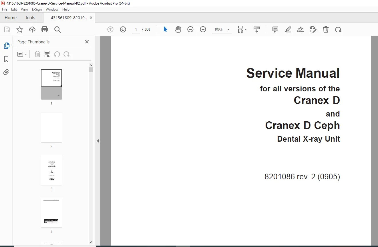
Official Soredex service manual for Cranex D and Cranex D Ceph digital dental x-ray units covering all versions including panoramic, TMJ, sinus, and cephalometric imaging systems. This comprehensive 308-page technical manual (Code 8201086 rev. 2, May 2009) includes installation, calibration, troubleshooting, maintenance, circuit diagrams, mechanical descriptions, CCD sensor service, annual service procedures, and complete parts replacement instructions for authorized dental equipment service technicians.
Description
Soredex Cranex D Ceph Service Manual PDF Dental X-Ray Unit Panoramic Digital – PDF DOWNLOAD
DESCRIPTION
This is the official Soredex Service Manual for Cranex D and Cranex D Ceph Dental X-Ray Units (Code 8201086 Revision 2, May 2009), covering all versions of these professional digital panoramic and cephalometric extraoral dental imaging systems. This comprehensive 308-page technical manual provides complete service information for Soredex-trained and authorized service personnel to install, calibrate, troubleshoot, maintain, and repair these advanced dental x-ray systems used in dental practices, oral surgery centers, and orthodontic clinics worldwide.
Product Overview
Soredex Cranex D and Cranex D Ceph:
The Cranex D series represents professional digital extraoral x-ray units designed specifically for imaging the dento-maxillofacial region. These systems combine precision mechanical movement with advanced digital imaging technology to capture high-quality panoramic, TMJ (temporomandibular joint), sinus, and cephalometric images for comprehensive dental diagnosis and treatment planning.
Key Applications:
- General dentistry practices
- Oral and maxillofacial surgery
- Orthodontic clinics
- Periodontics
- Endodontics
- TMJ specialists
- Dental implantology
- Forensic dentistry
- Dental schools and teaching facilities
Models Covered
Cranex D Pan:
- Panoramic imaging
- TMJ imaging
- Sinus imaging
- Optional carpel imaging (not available in USA)
Cranex D Pan/Ceph:
- All Pan functions plus:
- Cephalometric imaging
- Left-hand or right-hand ceph arm mounting
- Retrofit ceph arm kit available
Unit Versions:
- Versions 1 & 2 – Original “dark blue” control panel and GUI (Serial numbers B81642 and earlier)
- Version 3 – “Light grey” control panel and GUI (Serial numbers B91643 and later)
Key Features and Technologies
Digital Imaging:
- CCD (Charge-Coupled Device) image receptors
- Removable sensors
- Real-time image capture
- PC connectivity
- Compatible with Digora for Windows
- MDD-approved dental imaging software support
Imaging Modalities:
- Panoramic – Full mouth imaging
- TMJ – Temporomandibular joint imaging
- Sinus – Maxillary sinus imaging
- Cephalometric – Lateral and PA skull imaging (Ceph models)
- Carpel – Wrist imaging (optional, not USA)
Mechanical Systems:
- Precision rotation mechanism
- Motorized vertical carriage
- Automatic patient positioning
- Soft tissue filter (automatic)
- Adjustable patient positioning lights
- Column-mounted design
- Left or right ceph arm options
X-Ray Generation:
- Multiple tube head options:
- OPX/105
- DE 100/15ö
- D-051
- KL5
- Factory-set voltage (230 VAC or 115 VAC)
- Non-adjustable voltage setting
- Collimator with lead aperture plate
- Beam-limiting device compliance
Technical Specifications
Power Requirements:
- 230 VAC or 115 VAC (factory set, non-changeable)
- Power supply voltage marked on unit
- RF filtering
- Protective earth connection required
- Equipotential grounding
Radiation Safety:
- Compliance with 21 CFR 1020.30-32 (USA)
- Medical Device Directive 93/42/EEC
- Exposure warning lights
- Exposure warning signal
- Lead apron requirement
- 2-meter (6 feet) minimum operator distance
Control Systems:
- Microprocessor-based control
- Motor control systems
- Position control
- Exposure logic
- Image receptor detection
- Safety interlocks
Dimensions:
- Unit dimensions specified
- Floor space requirements
- Clearance specifications
- Wall-mounting configuration
Comprehensive Manual Contents
DOCUMENT INFORMATION:
- Code: 8201086
- Revision: 2 (0905)
- Publication Date: May 6, 2009
- Last Modified: June 17, 2009
- Pages: 308 pages
- Language: English
- Manufacturer: SOREDEX, Tuusula, Finland
COMPLETE TABLE OF CONTENTS
CHAPTER 1: GENERAL INFORMATION (Pages 1-6)
1.1 Introduction:
- Manual purpose and scope
- Service personnel requirements
- Soredex training and authorization
1.2 Unit Versions:
- Version 1 & 2 (s/n B81642 and earlier)
- Version 3 (s/n B91643 and later)
- Control panel differences
- GUI differences
1.3 Associated Documentation:
- Cranex D Pan/Ceph User’s Manual
- Cranex D Pan/Ceph Installation Manual
- Cranex D Pan/Ceph Spare-Parts Manual
1.4 Service Warnings and Precautions:
Servicing Precautions:
- Soredex trained personnel only
- Original spare parts requirement
- Factory voltage setting (non-changeable)
- User manual familiarity requirement
Radiation Safety:
- Local/national standards compliance
- Lead apron or radiation shield requirement
- 2-meter (6 feet) minimum distance
- Test exposure precautions
Mechanical Safety:
- Main power switch-off requirement
- Moving parts entrapment hazards
- Lead aperture plate toxicity (Pb)
- Hot surfaces during operation
- DO NOT open tube head
- No serviceable parts in tube head
Electrical Safety:
- Power switch-off before service
- Mains disconnection when leaving service area
- Live terminal dangers
- Protective earth requirement
- Equipotential ground connection
- Cleaning/disinfection power-off requirement
Electrostatic Discharge (ESD):
- ESD damage prevention
- Wrist strap requirement
- 1 Mohm current limiting cable
- Ground point connection
- Antistatic mat usage
- Wrist strap maintenance
Explosion Hazard:
- Disinfectant vapor dispersion
- Explosive vapor formation
- Ventilation before power-on
1.5 Operating Warnings and Precautions:
- Dental/TMJ/cephalometric use only
- No modifications allowed
- Authorized service only
- Radiation protection requirements
- Operator positioning (2 meters/6 feet)
- Patient visibility/audibility requirement
- Exposure warning visibility
- External warning light if needed
- Local radiation safety compliance
- Avoid pregnant women exposures
- IEC 601-1 compliant accessories
- RS-232C cable (versions 1 & 2 only)
- 3rd party software MDD compliance
- FDA compliance (if applicable)
1.6 Unauthorized Modifications:
- Hazardous consequences warning
- Soredex authorization requirement
- Federal Performance Standards compliance (21 CFR 1020.30-32)
- No tube head disassembly
- No beam-limiting device adjustment
- Soredex direction requirement
1.7 Disclaimer:
- Liability limitations
- Consequential damages disclaimer
- Warranty restrictions
CHAPTER 2: UNIT DESCRIPTION (Pages 7-30)
2.1 The Cranex D and Cranex D Ceph:
- Digital extraoral x-ray units
- Dento-maxillofacial region imaging only
- Panoramic, sinus, TMJ capabilities
- Cephalometric imaging (Pan/Ceph models)
- Left or right ceph arm mounting
- Retrofit ceph arm kit availability
- Carpel imaging adaptor (optional, not USA)
- 230 VAC or 115 VAC factory setting
- PC requirement with Digora for Windows
2.2 Unit Versions: Product identification label decoding:
- PP 1 0 1 2 – 0 1 2 format explanation
- Country/language codes (00-09, 2X, 3X)
- X-ray tube types (0-4)
- Unit type codes (0, 7, 8)
- Digital unit identification (0, 1)
- Production version (0-3)
2.3 Main Parts and Assemblies:
Cranex D Pan Components:
- Column assembly
- Rotation arm
- Tube head assembly
- Patient positioning system
- Control panel
- Vertical carriage
- Motor assemblies
- Sensor mounting
- Collimator system
Cranex D Pan/Ceph Additional Components:
- Cephalometric arm (left or right)
- Ceph sensor holder
- Ear rods
- Nasion pointer
- Ceph positioning system
- Ceph exposure system
2.4 User Interfaces:
Control Panel (s/n B81642 and earlier):
- Dark blue control panel
- Button layout
- Function keys
- Hidden keys (service mode)
- Test connector (SERVICESW 4801744)
- X90 connector on Digital I/O board (N5200)
- Test connector removal requirement
Graphical User Interface (s/n B81642 and earlier):
- Original GUI design
- Display functions
- Parameter settings
- Program selection
Control Panel (s/n B91643 and later):
- Light grey control panel
- Updated button layout
- Enhanced functions
- Service mode access
Graphical User Interface (s/n B91643 and later):
- Updated GUI design
- Enhanced display
- Improved functionality
- Modern interface
2.5 Unit Dimensions:
- Physical measurements
- Installation footprint
- Clearance requirements
- Wall mounting specifications
2.6 CCD Image Receptors (Sensors):
- Sensor types
- Mounting systems
- Connection methods
- LED status indicators
- Sensor debugging
2.7 Link to PC:
Unit Versions s/n B81642 and Earlier:
- RS-232C serial interface
- Manufacturer-supplied cable requirement
- Connection specifications
Unit Versions s/n B91643 and Later:
- Updated interface
- NO RS-232C cable required
- Direct PC connection
2.8 Mechanical Description:
- Rotation mechanism
- Drive systems
- Motor assemblies
- Positioning systems
- Vertical carriage operation
- Z-motor system
- Clutch mechanisms
2.9 Electrical Description:
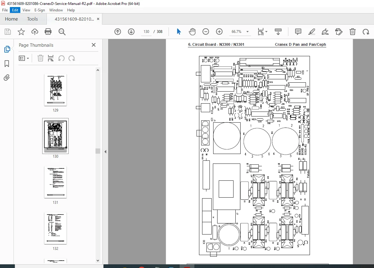
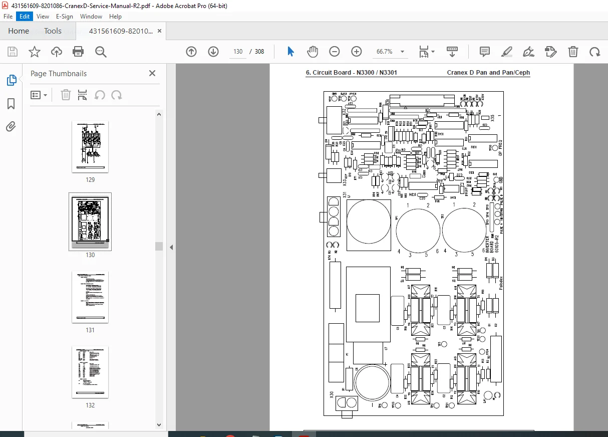
Circuit Board Names and Locations:
- Complete board inventory
- Board identification
- Physical locations
- Connector designations
- PCB part numbers
Power Supply:
- Power distribution
- Voltage regulation
- Protection circuits
- Fusing
Unit Control:
- Master control system
- Microprocessor functions
- Logic circuits
- Safety interlocks
Motors and Motor Control:
- Motor types
- Drive circuits
- Speed control
- Position feedback
- Torque specifications
Exposure Logic:
- Exposure initiation
- Timing control
- kV/mA control
- Safety interlocks
- Abort sequences
Position Control:
- Sensor systems
- Position detection
- Limit switches
- Home position detection
- Calibration procedures
Imaging Chain Overview:
- Signal flow
- Processing steps
- Image capture
- Data transmission
CHAPTERS 3-6: INSTALLATION, CALIBRATION, AND MAINTENANCE
(Detailed procedures covering installation, system calibration, alignment procedures, and routine maintenance)
CHAPTER 7: TROUBLESHOOTING (Pages 260-264)
7.4 Other Problems:
Soft Tissue Filter Issues:
- Filter not working
- Detection problems
- Mechanical failures
- Adjustment procedures
Patient Positioning Lights:
- Lights not illuminating
- Bulb failures
- Circuit problems
- Replacement procedures
Vertical Carriage Problems:
- Up/down key response failure
- Motor issues
- Control circuit problems
- Position sensor failures
- Mechanical binding
Sensor, Detector, Microswitch Problems:
- Detection failures
- Switch failures
- Wiring issues
- Adjustment procedures
Unit Won’t Power On:
- Power supply problems
- Fuse failures
- Main switch issues
- Safety interlock problems
7.5 CCD Problems:
CCD Sensor LEDs (Page 262):
- LED status indicators
- Normal operation patterns
- Fault indication patterns
- Diagnostic interpretation
Debugging Software (Page 264):
- Software diagnostic tools
- Error code interpretation
- Log file analysis
- Troubleshooting procedures
CHAPTER 8: REPLACING PARTS (Pages 265-267)
8.1 Replacing the Tube Head (Page 265):
- Tube head removal procedures
- Electrical disconnection
- Mechanical disassembly
- New tube head installation
- Alignment procedures
- Testing and verification
8.2 Adjusting Panoramic Slit Collimator (Page 266):
- Collimator adjustment procedures
- Alignment requirements
- Verification methods
- Test exposure procedures
8.3 Releasing a Jammed Z-Motor (Page 267):
- Z-motor jam diagnosis
- Manual release procedures
- Clutch disengagement
- Motor inspection
- Re-engagement procedures
CHAPTER 9: ANNUAL SERVICE (Pages 268-274)
9.1 mA Test (Page 268):
- Current measurement procedures
- Test equipment requirements
- Acceptable ranges
- Calibration procedures
9.2 kV Test (Page 269):
- Voltage measurement procedures
- Test equipment requirements
- Acceptable ranges
- Calibration procedures
9.3 Exposure Time Test (Pan/Ceph Units Only) (Page 270):
- Timing verification
- Test procedures
- Acceptable tolerances
- Adjustment methods
9.4 Motor Movements (Page 270):
- Motor function testing
- Movement verification
- Speed checks
- Smoothness assessment
9.5 Position Detectors (Page 271):
- Sensor verification
- Detection accuracy
- Adjustment procedures
- Replacement criteria
9.6 Image Receptor Detection (Page 271):
- Sensor detection testing
- Auto-recognition verification
- Signal verification
9.7 Panoramic Alignment (Page 271):
- Alignment verification
- Test procedures
- Adjustment methods
- Acceptance criteria
9.8 Cephalometric Alignment (Page 272):
- Ceph arm alignment
- Positioning accuracy
- Adjustment procedures
- Verification tests
9.10 Soft Filter Alignment (Page 273):
- Filter positioning
- Alignment verification
- Adjustment procedures
9.11 Patient Positioning Lights (Page 273):
- Light function testing
- Bulb inspection
- Alignment verification
- Replacement procedures
9.12 Covers and Labels (Page 273):
- Cover integrity inspection
- Label legibility check
- Warning label verification
- Replacement procedures
9.13 Other Checks (Page 274):
- General inspection checklist
- Safety verification
- Documentation requirements
- Service record completion
CHAPTER 10: IMAGE APPEARANCE (Page 275)
(For s/n B81642 and earlier only)
10.1 Using 16-bit Format:
- Image format selection
- Advantages/disadvantages
- Conversion procedures
10.2 Setting 16-bit Filtering:
- Filter parameter adjustment
- Image quality optimization
- Parameter changes
APPENDICES
Appendix A1: Technical Information (Pages A1-1+):
- Complete specifications
- Performance data
- Electrical schematics
- Mechanical drawings
- Parts diagrams
Appendix A2: Upgrading Pan to Pan/Ceph (Pages A2-1 to A2-8):
A2.1 Replacing the Collimator:
- Collimator removal
- New collimator installation
- Alignment procedures
A2.2 Installing Cephalometric Unit:
- Ceph arm installation
- Mechanical assembly
- Positioning system setup
A2.3 Electrical Modifications:
- Wiring changes
- Board upgrades
- Connector additions
- Testing procedures
A2.4 Software Modifications:
- Software updates
- Configuration changes
- Program installation
- Verification procedures
A2.5 Checking Unit Alignment:
- Post-upgrade alignment
- Comprehensive testing
- Final verification
Appendix A3: Software Versions (Pages A3-1+):
- Software revision history
- Version compatibility
- Update procedures
- Feature changes
Who Needs This Manual?
This Soredex Cranex D service manual is essential for:
- Soredex-trained service technicians
- Authorized Soredex service centers
- Dental equipment service companies
- Biomedical equipment technicians (dental)
- Dental practice technical staff
- Anyone performing authorized service on Cranex D units
Prerequisites:
✓ Soredex service training and authorization
✓ Dental x-ray equipment experience
✓ Radiation safety certification
✓ Electronic troubleshooting skills
✓ Mechanical repair aptitude
✓ ESD handling procedures
✓ Familiarity with Cranex D operation
FILE DETAILS
| Detail | Specification |
|---|---|
| Manual Title | Service Manual for all versions of the Cranex D and Cranex D Ceph Dental X-ray Unit |
| Models Covered | Cranex D Pan, Cranex D Pan/Ceph (all versions) |
| Code | 8201086 |
| Revision | 2 (0905) |
| Publication Date | May 6, 2009 |
| Last Modified | June 17, 2009 |
| Manufacturer | SOREDEX, P.O. Box 148, FIN-04301 Tuusula, Finland |
| Pages | 308 pages |
| PDF Quality | High-quality professional service manual with diagrams |
| File Size | 4.8 MB |
| Page Size | A4 (595 x 842 pts) |
| Language | English |
| Creator | PageMaker 7.0 |
| Author | 1010015 |
| Regulatory | Medical Device Directive 93/42/EEC, 21 CFR 1020.30-32 |
| PDF Version | 1.4 |