Trusted Business
Verified & Licensed
Virus Free Files
100% Safe Downloads
Secure Payment
SSL Protected
Instant Delivery
Available Immediately
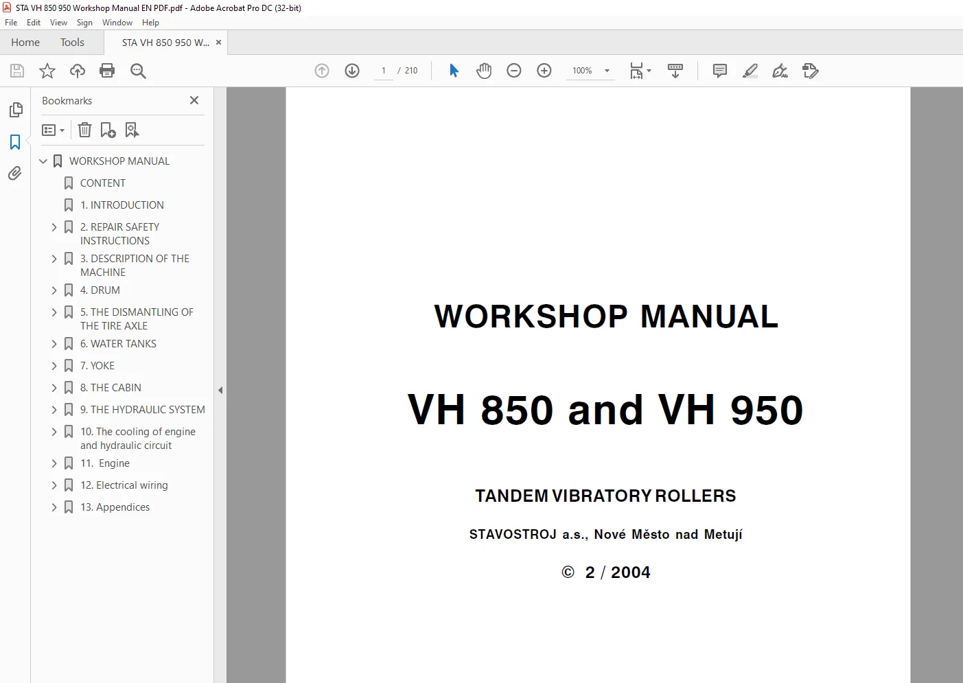
STA VH 850 & VH 950 TANDEM VIBRATORY ROLLERS WORKSHOP MANUAL – PDF DOWNLOAD
$27.95
STA VH 850 & VH 950 TANDEM VIBRATORY ROLLERS WORKSHOP MANUAL – PDF DOWNLOAD
Instant PDF Download
Available immediately
Save to Your Device
Download & keep forever
Antivirus Scanned
100% virus-free
Trusted Worldwide
175,000+ customers
Description
STA VH 850 & VH 950 TANDEM VIBRATORY ROLLERS WORKSHOP MANUAL – PDF DOWNLOAD
FILE DETAILS:
STA VH 850 & VH 950 TANDEM VIBRATORY ROLLERS WORKSHOP MANUAL – PDF DOWNLOAD
Language : English
Pages : 210
Downloadable : Yes
File Type : PDF
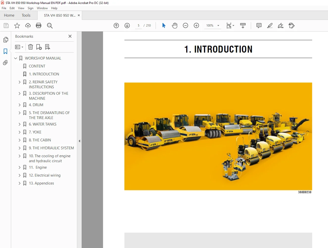
IMAGES PREVIEW OF THE MANUAL:
DESCRIPTION:
STA VH 850 & VH 950 TANDEM VIBRATORY ROLLERS WORKSHOP MANUAL – PDF DOWNLOAD
- This service manual consists of independent chapters dealing with both technical and assembling data, adjustment instructions and the guideline how to use special tools, jigs, fixtures and aids.
- The main purpose of this manual is to provide basic information for assembly, dismantling and service repairs of main assemblies of the machine.
- The unit assemblies are marked in this manual in the same way as in the spare parts catalogue.
- Before the dismounting, we recommend you to mark the parts disassembled keeping in mind the way how they will be put back and to blind all holes of the hydraulic system to prevent contamination of hydraulic circuits.
- During assembling the parts to the machine, tighten each bolt or nut according to the tightening torque table (Chapter 13.6.) if it is not stipulated otherwise in the text.
- Always follow safety regulations and measures shown in Chapter 2.
- The manufacturer is continuously improving his products on the basis of operational experience and latest developments. He, therefore, retains the right to make changes, on the basis of research and development, as compared with Figures, descriptions, procedures and designs given in this manual.
- Terms such as in the right-hand, left-hand, front or back are used in this manual for the customer’s information – that means when the machine goes forward.
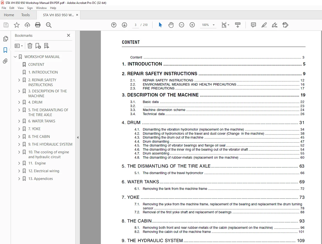
TABLE OF CONTENTS:
STA VH 850 & VH 950 TANDEM VIBRATORY ROLLERS WORKSHOP MANUAL – PDF DOWNLOAD
WORKSHOP MANUAL.............................................................................................................  1
	CONTENT ................................................................................................................  3
	1. INTRODUCTION ........................................................................................................  5
	2. REPAIR SAFETY INSTRUCTIONS ..........................................................................................  9
		2.1. Repair safety instructions .................................................................................... 12
		2.2. Environmental measures and health precautions ................................................................. 16
		2.3. Fire precautions .............................................................................................. 17
	3. DESCRIPTION OF THE MACHINE .......................................................................................... 19
		3.1. Basic data .................................................................................................... 22
		3.2. Machine design ................................................................................................ 23
		3.3. Machine dimension scheme ...................................................................................... 24
		3.4. Technical data ................................................................................................ 26
	4. DRUM................................................................................................................. 31
		4.1. DISMANTLING THE VIBRATION HYDROMOTOR (REPLACEMENT ON THE MACHINE).............................................. 34
		4.2. DISMANTLING OF HYDROMOTORS OF THE TRAVEL AND DUST COVER (CHANGE IN THE MACHINE)................................ 38
		4.3. DISMANTLING THE DRUM OUT OF THE MACHINE........................................................................ 45
		4.4. DRUM DISMANTLING............................................................................................... 47
		4.5. THE DISMANTLING OF VIBRATOR BEARINGS AND FLANGE OIL SEAL....................................................... 52
		4.6. THE DISMANTLING OF THE INNER RING OF THE BEARING OUT OF THE VIBRATOR SHAFT..................................... 54
		4.7. DRUM ASSEMBLING................................................................................................ 55
		4.8. THE DISMANTLING OF RUBBER-METALS (REPLACEMENT ON THE MACHINE).................................................. 60
	5. THE DISMANTLING OF THE TIRE AXLE..................................................................................... 63
		5.1. THE DISMANTLING OF THE TRAVEL HYDROMOTOR....................................................................... 66
	6. WATER TANKS.......................................................................................................... 69
		6.1. REMOVING THE TANK FROM THE MACHINE
FRAME...................................................................... 72
	7. YOKE................................................................................................................. 73
		7.1. REMOVAL THE YOKE FROM THE MACHINE FRAME, REPLACEMENT OF THE BEARING AND REPLACEMENT THE DRUM TURNING SENSOR.... 78
		7.2. REMOVAL OF THE FIRST YOKE SHAFT AND REPLACEMENT OF BEARINGS.................................................... 88
	8. THE CABIN............................................................................................................ 93
		8.1. REMOVING BOTH FRONT AND REAR RUBBER-METALS OF THE CABIN (REPLACEMENT ON THE MACHINE)........................... 96
		8.2. REMOVING THE CABIN OUT OF THE MACHINE FRAME....................................................................101
	9. THE HYDRAULIC SYSTEM.................................................................................................109
		9.1. DISMANTLING HYDROMOTORS FOR  STEERING AND LIFTING (PACKING REPLACEMENT)........................................114
		9.2. THE ASSEMBLY OF HYDROMOTORS FOR STEERING AND LIFTING (PACKING REPLACEMENT).....................................116
		9.3. DISMANTLING PUMPS OF TRAVEL AND  VIBRATION (REPLACEMENT ON THE MACHINE)........................................118
		9.4. DISMANTLING THE CLUTCH OF THE PUMP FOR TRAVEL AND VIBRATION (REPLACEMENT ON THE MACHINE).......................120
		9.5. DISMANTLING THE STEERING PUMP (REPLACEMENT ON THE MACHINE).....................................................121
		9.6. HYDRAULIC DIAGRAMS.............................................................................................123
	10. The cooling of engine and hydraulic circuit ........................................................................131
		10.1. Removal of the wather and of the oil cooler (replacement on the machine) .....................................134
	11.  Engine ............................................................................................................137
		11.1. Removal of the engine from the machine  ......................................................................140
	12. Electrical wiring ..................................................................................................143
		12.1. Layout of electric components in the machine .................................................................146
		12.2. Fuse box .....................................................................................................148
		12.3. Accumulator ..................................................................................................149
		12.4. Exchange bulbs headlights ....................................................................................150
		12.5. Exchange bulbs of dashboard ..................................................................................152
		12.6. Wiring diagram ...............................................................................................154
	13. Appendices .........................................................................................................157
		13.1. Measuring points .............................................................................................160
		13.2. Pulse sensors adjustment .....................................................................................162
		13.3. Vibration adjustment .........................................................................................166
		13.4. Towing .......................................................................................................167
		13.5. Troubleshooting ..............................................................................................176
		13.6. Table of tightening moments ..................................................................................204
		13.7. List fixtures ................................................................................................207
Questions? Email us: [email protected]
https://vimeo.com/892850194?share=copy
S.S