Trusted Business
Verified & Licensed
Virus Free Files
100% Safe Downloads
Secure Payment
SSL Protected
Instant Delivery
Available Immediately
STA VP 2400 Rubber-Tyred Roller Workshop Manual – PDF DOWNLOAD
$23.95
STA VP 2400 Rubber-Tyred Roller Workshop Manual – PDF DOWNLOAD
Instant PDF Download
Available immediately
Save to Your Device
Download & keep forever
Antivirus Scanned
100% virus-free
Trusted Worldwide
175,000+ customers
Description
STA VP 2400 Rubber-Tyred Roller Workshop Manual – PDF DOWNLOAD
FILE DETAILS:
STA VP 2400 Rubber-Tyred Roller Workshop Manual – PDF DOWNLOAD
Language : English
Pages : 124
Downloadable : Yes
File Type : PDF
IMAGES PREVIEW OF THE MANUAL:
DESCRIPTION:
STA VP 2400 Rubber-Tyred Roller Workshop Manual – PDF DOWNLOAD
- The roller, series VP 2400, is designed for compacting operations of medium to large magnitudes in the construction of highways, railroads, airports, dams, industrial tracts, harbors, etc. Specifications of the machine, weight, tire sizes, turning radius, leveling of front wheels, and the first-rate engine, provide for an efficient roller with very good output, high reliability, and safety in operations. The fact that the inflation of tires can be adjusted continuously allows for compacting of all kinds of materials in a wide range of consistency, and for the optimal adaptation of the roller.
- The roller is well suited for compacting asphalt mixtures, hydraulically compacted mixtures, clay soils, and soil mixtures of sand and gravel. However, it is nor suited for rockfills.
- The roller operates under conditions specified in standards CSN IEC 721-2-1 (038900): WT, WDr, MWDr – that is mild, warm and dry, hot and dry environment at temperatures of –15 °C (5 °F) to 45 °C (113 °F).
- The roller is manufactured to most modern rules and standards of work safety.
- There exists danger of damage or injury, should the roller be applied incorrectly, by untrained personnel, or for other than specified purposes.
- The main purpose of this manual is to provide basic information for the disassembly, assembly, and service of the main construction elements of the roller. The manual consists of separate chapters in reference to the catalogue of spare parts, and contains data on assembly, adjustment, and instructions for the application of special tools and fixtures.
- The manufacturer improves the product continually under application of the most recently gained experience and know-how, and for that reason, reserves the right to install modifications that have not been included in the pictures, descriptions, and/ or construction details of this manual.
- This Manual is copyrighted and it is not permitted to copy and distribute it or its parts.
- The text in this Manual refers to right, left, forward, or backward from the direction of forward travel.
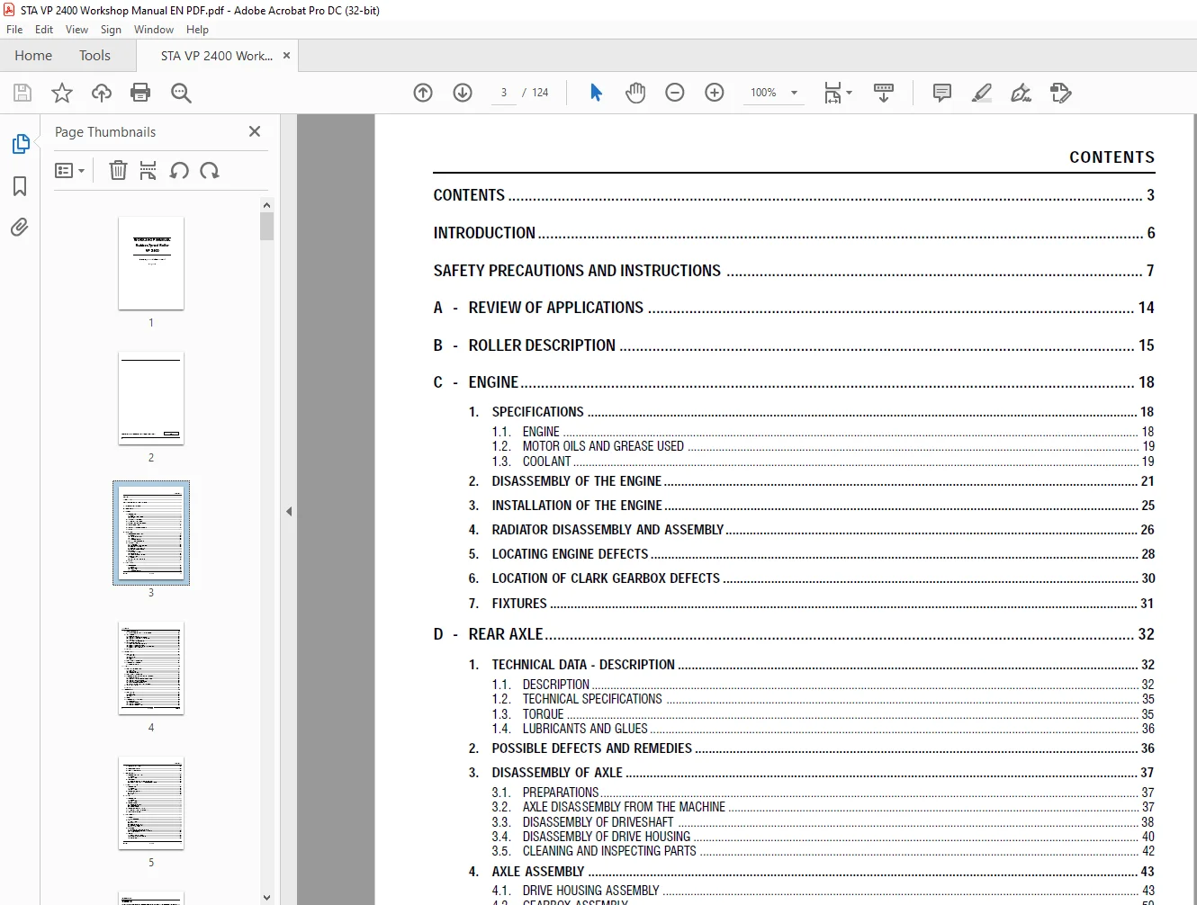
TABLE OF CONTENTS:
STA VP 2400 Rubber-Tyred Roller Workshop Manual – PDF DOWNLOAD
WORKSHOP MANUAL.........................................................  1
	CONTENTS ...........................................................  3
	INTRODUCTION .......................................................  6
	SAFETY PRECAUTIONS AND INSTRUCTIONS ................................  7
	A - REVIEW OF APPLICATIONS ......................................... 14
	B - ROLLER DESCRIPTION ............................................. 15
	C - ENGINE ......................................................... 18
		1. Specifications .............................................. 18
		1.1. Engine .................................................... 18
		1.2. Motor oils and grease used ................................ 19
		1.3. Coolant ................................................... 19
		2. Disassembly of the engine ................................... 21
		3. Installation of the engine .................................. 25
		4. Radiator disassembly and assembly ........................... 26
		5. Locating engine defects ..................................... 28
		6. Location of CLARK gearbox defects ........................... 30
		7. FIXTURES .................................................... 31
	D - REAR AXLE ...................................................... 32
		1. TECHNICAL DATA - DESCRIPTION ................................ 32
		1.1. Description ............................................... 32
		1.2. Technical specifications .................................. 35
		1.3. Torque .................................................... 35
		1.4. Lubricants and glues  ..................................... 36
		2. POSSIBLE DEFECTS AND REMEDIES ............................... 36
		3. DISASSEMBLY OF AXLE ......................................... 37
		3.1. Preparations .............................................. 37
		3.2. Axle disassembly from the machine ......................... 37
		3.3. DISASSEMBLY OF DRIVESHAFT ................................. 38
		3.4. disassembly OF Drive housing  ............................. 40
		3.5. Cleaning and inspecting parts ............................. 42
		4. AXLE ASSEMBLY ............................................... 43
		4.1. Drive housing assembly .................................... 43
		4.2. Gearbox assembly .......................................... 50
		4.3. Assembling axle to the machine ............................ 53
		5. Differential lock ........................................... 54
		5.1. DESCRIPTION ............................................... 54
		5.2. Possible defects and remedies ............................. 56
		6. FIXTURES .................................................... 57
	E - FRONT AXLE ..................................................... 58
		1. TECHNICAL DATA .............................................. 58
		1.1. Description ............................................... 58
		1.2. Specifications ............................................ 58
		1.3. Torque values ............................................. 59
		1.4. Lubricants and glues ...................................... 59
		2. DEFECTS AND REMEDIES ........................................ 60
		2.1. Inspection of installation of four front wheels  .......... 60
		3. AXLE DISASSEMBLY ............................................ 61
		3.1. Preparatory work .......................................... 61
		3.2. Disassembly of axle from the equipment  ................... 62
		3.3. Disassembly of guiding pipe of the front axle ............. 63
		3.4. Disassembly of fork ....................................... 64
		3.5. Cleaning and inspection of parts .......................... 66
		4. INSTALLATION OF FRONT AXLE .................................. 67
		4.1. Installation of guiding pipe and fork ..................... 67
		4.2. Assembly of wheel hubs and shaft .......................... 69
		4.3. Assembly of fork and shaft assembly with wheel hubs ....... 71
		4.4. Assembly of axle to the machine ........................... 73
		5. FIXTURES .................................................... 74
	f - FLEXIBLE SHAFT ................................................. 77
		1. Specifications .............................................. 77
		1.1. Description ............................................... 77
		1.2. Specifications ............................................ 77
		1.3. Torque .................................................... 77
		1.4. Grease .................................................... 77
		2. Possible defects and remedies ............................... 78
		3. Disassembly and re-assembly ................................. 78
		3.1. Preparatory work .......................................... 78
	G - STEERING ....................................................... 79
		1. Specifications - description ................................ 79
		1.1. Description ............................................... 79
		1.2. Technical data ............................................ 79
		1.3. Lubricants and glues ...................................... 82
		2. Possible defects and remedies ............................... 83
		3. DISASSEMBLY AND ASSEMBLY OF THE STEERING ASSEMBLY ........... 84
		3.1. Preparatory work .......................................... 84
		3.2. DISASSEMBLY OF STEERING hydraulic generator  u10 .......... 85
		3.3. DISASSEMBLY OF POWER STEERING ............................. 86
		3.4. DISASSEMBLY OF LINEAR hydraulic motor   ................... 87
		3.5. Removal of power steering tank ............................ 88
		3.6. Removal and installation of the lever assembly  ........... 89
		4. Adjustment of toe-in ........................................ 90
		5. Fixtures .................................................... 92
	H - SERVICE BRAKE .................................................. 93
		1. Specifications .............................................. 93
		1.1. Description ............................................... 93
		1.2. Specifications ............................................ 96
		1.3. Brake fluid ............................................... 98
		2. Defects ..................................................... 98
		3. Disassembly and installation  ...............................100
		3.1. Preparations ..............................................100
		3.2.  Disassembly of pedal brake ...............................100
		3.3. Disassembly of booster ....................................101
		3.4. Disassembly of brake system ...............................102
		4. Brake shoes adjustment ......................................103
		5. Service brake venting .......................................104
		6. Machining brake drums .......................................104
	I - PARKING BRAKE ..................................................105
		1. Specifications - description ................................105
		1.1. Description ...............................................105
		1.2. Specifications ............................................105
		2. Maintenance .................................................106
		2.1. Disassembly and installation of the disk brake ............106
		2.2. Removal and installation of the spring-loaded cylinder ....107
	J - INFLATING THE TIRES ............................................108
		1. Specifications ..............................................108
		1.1. Description ...............................................108
		1.2. Specifications ............................................108
		2. Removal and installation ....................................109
		2.1. Control valve .............................................109
		2.2. Rotor  ....................................................109
	K - WHEELS .........................................................110
		1. Specifications ..............................................110
		1.1. Description ...............................................110
		1.2. Specifications ............................................110
		2. Removal of wheels ...........................................110
		2.1. Preparation for work ......................................110
		2.2. Front axle wheels .........................................110
		2.3. Rear axle wheels ..........................................111
		3. Removal and installation of tires ...........................112
		4. Installation of wheel to the machine ........................112
		5. Safety valve adjustment .....................................112
	L - Electrical wiring ..............................................113
		1. DESCRIPTION .................................................113
		1.1. Battery breaker ...........................................114
		2. Battery .....................................................116
		2.1. Specifications ............................................116
		2.2. Operation .................................................116
		2.3. Indications of full charge ................................117
		2.4. Service during operations .................................117
		2.5. Safety regulations ........................................118
		3. Alternator ..................................................119
		3.1. Checking the alternator on the roller .....................119
		3.2. Determining defects of alternator-regulator ...............120
		3.3. Voltage regulator .........................................120
		4. Starter .....................................................121
		4.1. Operation and maintenance .................................121
		4.2. Check of idling - on the machine ..........................121
		4.3. Starter defects ...........................................121
Contact us: [email protected]
https://vimeo.com/892870895?share=copy
S.S