Stihl Fs240 260 360 410 460 Service Manual – PDF Download
Original price was: $26.95.$19.95Current price is: $19.95.
Stihl Fs240 260 360 410 460 Service Manual
Description
Stihl Fs240 260 360 410 460 Service Manual
FILE DETAILS:
FILE TYPE:PDF
DOWNLOADABLE:YES
MANUAL LANGUAGE:ENGLISH
PAGES:134
DESCRIPTION:
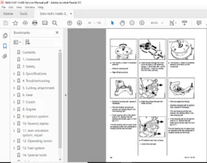
- This Service Manual contains detailed descriptions of all the typical repair and servicing procedures for this machine. Refer to the illustrated spare parts lists during all repair work. These lists show the installation position and order in which the individual parts and modules should be assembled. Refer to the latest edition of the relevant spare parts list to check the part numbers of any spare parts required.
- A fault on the machine may be due to several causes. To help locate the fault, consult the chapter on “Troubleshooting” and the “STIHL Service Training System” for all functional groups. Refer to the “Technical Information” bulletins for engineering changes which have been introduced since publication of this Service Manual. Technical information bulletins also supplement the spare parts list and Service Manual until an updated edition is issued.
TABLE OF CONTENTS:
- Stihl Fs240 260 360 410 460 Service Manual
1. Introduction and safety precautions 3
1.1 Introduction 3
1.2 Safety precautions 4
2. Specifications 5
2.1 Engine 5
2.2 Fuel system 5
2.3 Ignition system 5
2.4 Gearbox 5
2.5 Tightening torques 6
3. Troubleshooting 8
3.1 Clutch 8
3.2 Gearbox 9
3.3 Drive tube assembly 10
3.4 Starter 11
3.5 Ignition system 13
3.6 Carburetor 14
3.7 Engine 18
4. Clutch 19
4.1 Clutch drum 19
4.1.1 Ball bearing 22
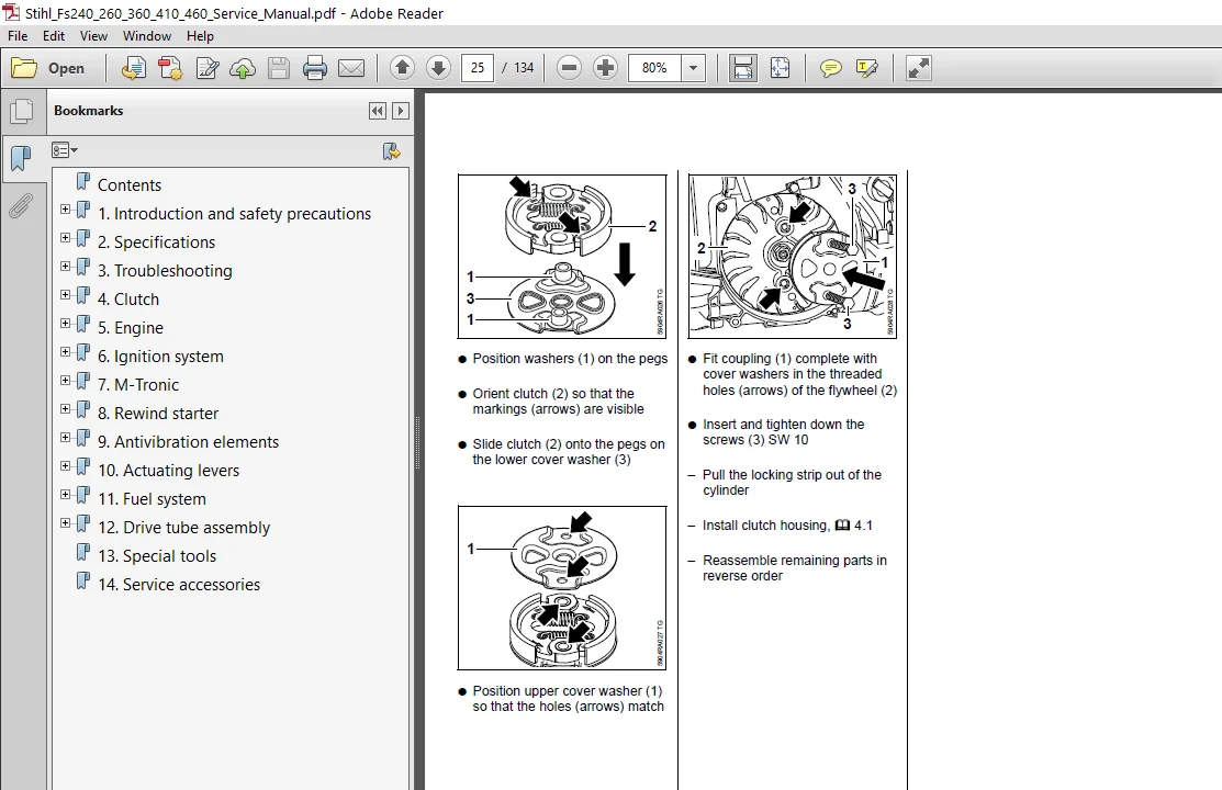
4.2 Clutch 23
5. Engine 25
5.1 Muffler 25
5.2 Leak testing 26
5.2.1 Preparations 26
5.2.2 Vacuum test 27
5.2.3 Pressure test 27
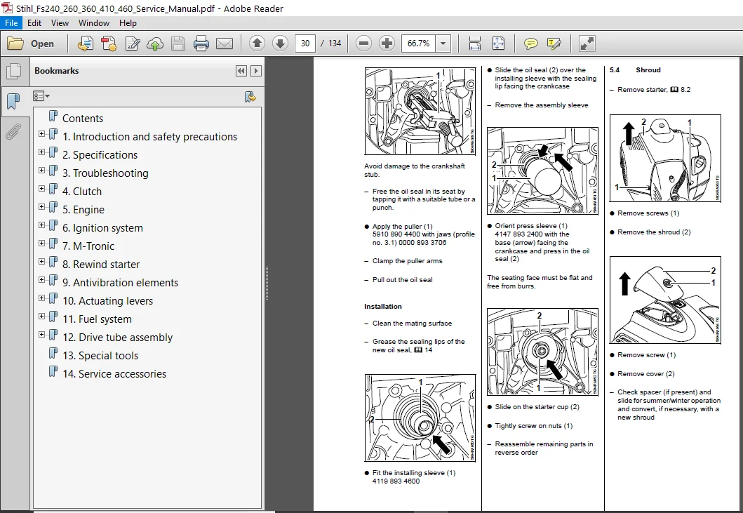
5.3 Oil seals 28
5.4 Shroud 29
5.5 Cylinder 30
5.6 Crankshaft 32
5.6.1 Ball bearing / crankcase 35
5.7 Piston 36
5.8 Piston rings 38
6. Ignition system 39
6.1 Ignition timing 39
6.2 Ignition module 39
6.2.1 Control unit (ignition module)
M-Tronic 41
6.3 Testing the
ignition module 42
6.4 Spark plug boot /
ignition lead 43
6.5 Flywheel 45
6.6 Short circuit wire 45
6.6.1 Testing 45
6.6.2 Short circuit wire on engine, removal and installation 46
6.6.3 Short circuit wire with M-Tronic on engine, removal and installation 48
6.6.4 Short circuit wire on
control handle for
loop handle,
removal and
installation 51
6.6.5 Short circuit wire
on control handle
for bike handle,
removal and
installation 52
6.6.6 Ground wire 54
6.6.7 Contact spring
versions with control
handle for bike handle 54
6.7 Troubleshooting,
Ignition System 55
7. M-Tronic 58
7.1 Calibrating
the control unit 58
7.2 Resetting the control
unit to factory defaults 58
7.3 Testing 58
7.3.1 Test preparations 58
7.3.2 Connect the test lead 58
7.3.3 Check screwed and
plug connections as
well as switch 59
7.3.4 Checking the solenoid
valve 59
7.3.5 Checking the start
detection function 60
7.3.6 Checking the wiring
harness 60
7.4 Removal and
installation 62
7.5 Troubleshooting,
M-Tronic 65
7.5.1 Engine does not start 65
7.5.2 Engine does not start
in position} 66
7.5.3 Engine speed drops
under load
– low power 67
7.5.4 Ignition – no ignition
spark 68
7.5.5 Engine stops
suddenly 69
7.5.6 Cut-off speed
not reached 70
8. Rewind starter 71
8.1 General 71
8.2 Starter 71
8.3 Pawls 71
8.4 ErgoStart/rope rotor 72
8.5 Starter rope /
starter grip 73
8.6 Tensioning
the rewind spring 75
8.7 Replacing
9. Antivibration
elements 77
9.1 Rubber insert
1-point antivibration
system 77
9.2 Rubber buffers/
springs 4-point
antivibration system 78
10. Actuating levers 82
10.1 Control handle for
loop handle 82
10.1.1 Throttle trigger /
throttle trigger
interlock 82
10.1.2 Slide control 84
10.2 Control handle
for bike handle 85
10.2.1 Removal and
installation 85
10.2.2 Throttle trigger /
throttle trigger
interlock 86
10.2.3 Lever for stop function 89
10.2.4 Adjusting
the throttle cable 89
10.2.5 Throttle rod 90
11. Fuel system 91
11.1 Air filter 91
11.2 Filter housing 91
11.3 Carburetor 93
11.3.1 Leakage test 95
11.4 Repairing
the carburetor 96
11.4.1 Metering diaphragm 96
11.4.2 Inlet needle 97
11.4.3 Pump diaphragm 98
11.4.4 Throttle shaft lever 99
11.4.5 Choke lever/choke
knob 100
11.4.6 Adjusting screws,
carburetor
without M-Tronic 102
11.5 Carburetor
adjustment
with M-Tronic 103
11.6 Carburetor
adjustment
without M-Tronic 103
11.6.1 Basic setting 103
11.6.2 User adjustment 104
11.7 Spacer flange 105
11.8 Tank vent 107
11.8.1 Testing 107
11.8.2 Removal
and installation 108
11.9 Fuel intake 108
11.9.1 Pickup body 108
11.9.2 Fuel hose 109
11.9.3 Fuel tank 110
12. Drive tube assembly 112
12.1 Drive tube assembly
with loop handle 112
12.2 Drive tube assembly
with control handle
for bike handle 113
12.2.1 Disassembling
the drive tube
assembly with a
diameter of 25.4 mm 114
12.2.2 Disassembling
the drive tube
assembly with a
diameter of 28 mm 116
12.2.3 Loop handle
with barrier bar 117
12.3 Deflector 118
12.3.1 Deflector for
gearbox with 25.4 mm
drive tube assembly
diameter 118
12.3.2 Deflector for gearbox
with 28 mm drive tube
assembly diameter 119
12.3.3 One-piece
carrying ring 120
12.3.4 Support 120
12.4 Gearbox for drive tube
assembly 25.4 mm
with square profile 120
12.4.1 Removal and
installation 120
12.4.2 Disassembly 121
12.5 Gearbox for drive tube
assembly 28 mm
with serration 124
12.5.1 Removal and installation 124
12.5.2 Disassembly 124
13. Special tools 129
14. Service accessories 131
the rewind spring 75
SCREENSHOT OF THE MANUAL:
STIHL FS240 260 360 410 460 SERVICE MANUAL – PDF DOWNLOAD:
PLEASE NOTE:
⦁ This is the SAME exact manual used by your dealers to fix your vehicle.
⦁ The same can be yours in the next 2-3 mins as you will be directed to the download page immediately after paying for the manual.
⦁ Any queries / doubts regarding your purchase, please feel free to contact [email protected]