Still Deutz TCD 4.1 L4 Industry EU Stage IV US EPA Tier4 Workshop Manual – PDF DOWNLOAD
$26.95
Still Deutz TCD 4.1 L4 Industry EU Stage IV US EPA Tier4 Workshop Manual – PDF DOWNLOAD
Description
Still Deutz TCD 4.1 L4 Industry EU Stage IV US EPA Tier4 Workshop Manual – PDF DOWNLOAD
FILE DETAILS:
Still Deutz TCD 4.1 L4 Industry EU Stage IV US EPA Tier4 Workshop Manual – PDF DOWNLOAD
Language : English
Pages : 284
Downloadable : Yes
File Type : PDF
DESCRIPTION:
Still Deutz TCD 4.1 L4 Industry EU Stage IV US EPA Tier4 Workshop Manual – PDF DOWNLOAD
IMAGES PREVIEW OF THE MANUAL:
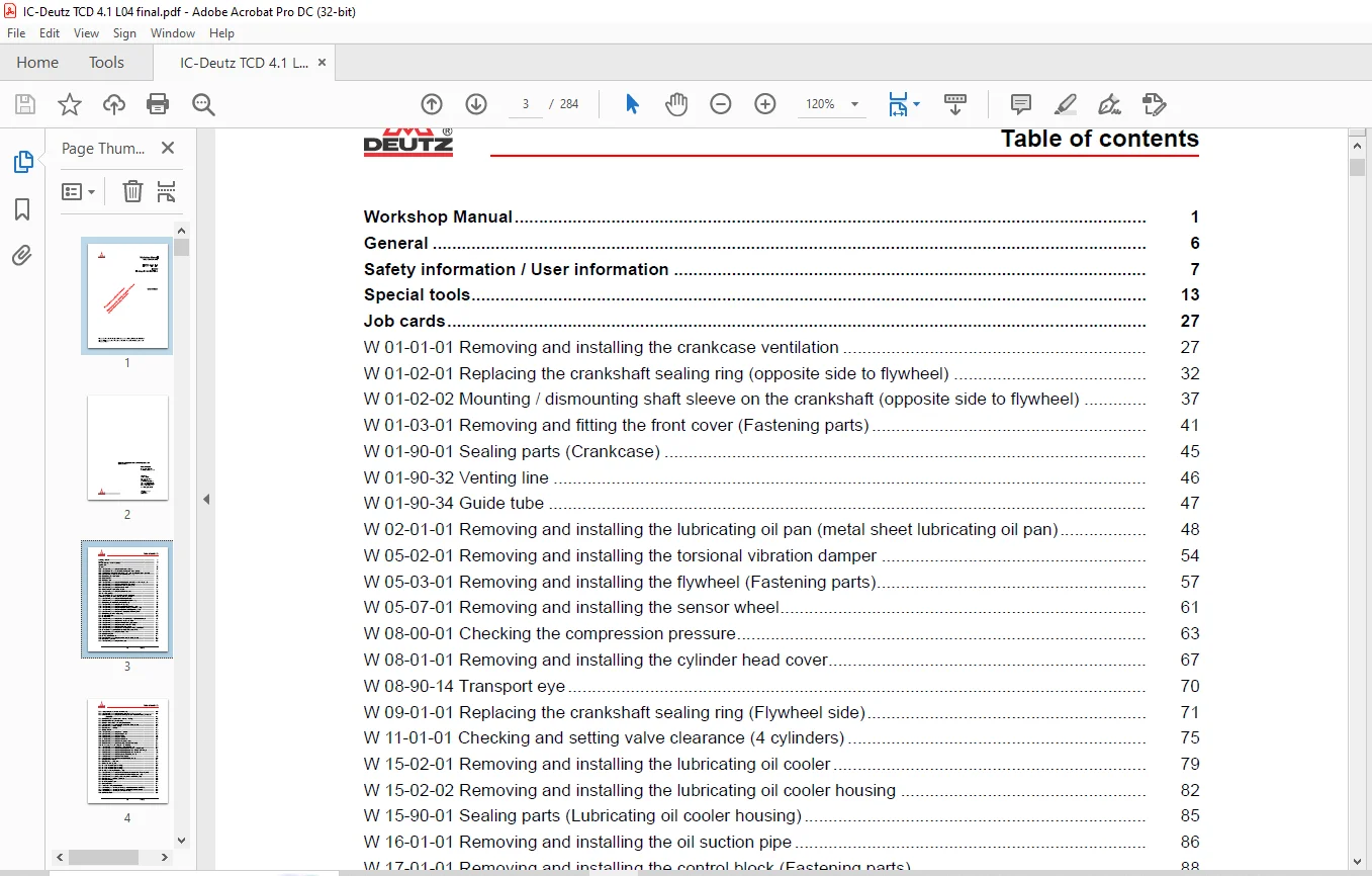
TABLE OF CONTENTS:
Still Deutz TCD 4.1 L4 Industry EU Stage IV US EPA Tier4 Workshop Manual – PDF DOWNLOAD
Workshop Manual 1
General 6
Safety information / User information 7
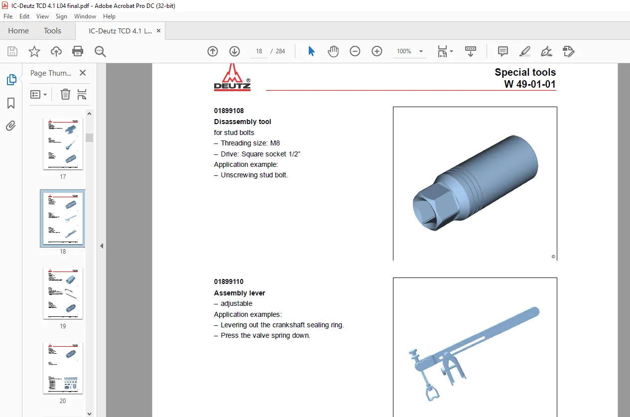
Special tools 13
Job cards 27
W 01-01-01 Removing and installing the crankcase ventilation 27
W 01-02-01 Replacing the crankshaft sealing ring (opposite side to flywheel) 32
W 01-02-02 Mounting / dismounting shaft sleeve on the crankshaft (opposite side to flywheel) 37
W 01-03-01 Removing and fitting the front cover (Fastening parts) 41
W 01-90-01 Sealing parts (Crankcase) 45
W 01-90-32 Venting line 46
W 01-90-34 Guide tube 47
W 02-01-01 Removing and installing the lubricating oil pan (metal sheet lubricating oil pan) 48
W 05-02-01 Removing and installing the torsional vibration damper 54
W 05-03-01 Removing and installing the flywheel (Fastening parts) 57
W 05-07-01 Removing and installing the sensor wheel 61
W 08-00-01 Checking the compression pressure 63
W 08-01-01 Removing and installing the cylinder head cover 67
W 08-90-14 Transport eye 70
W 09-01-01 Replacing the crankshaft sealing ring (Flywheel side) 71
W 11-01-01 Checking and setting valve clearance (4 cylinders) 75
W 15-02-01 Removing and installing the lubricating oil cooler 79
W 15-02-02 Removing and installing the lubricating oil cooler housing 82
W 15-90-01 Sealing parts (Lubricating oil cooler housing) 85
W 16-01-01 Removing and installing the oil suction pipe 86
W 17-01-01 Removing and installing the control block (Fastening parts) 88
W 17-01-04 Removing and installing the high-pressure pump (Fastening parts) 91
W 19-01-01 Removing and installing the injector (1600xbar injection system) 96
W 20-02-01 Removing and installing the fuel supply pump (Fastening parts) 107
W 20-90-01 Sealing parts (Fuel supply pump) 109
W 20-90-16 Fuel pre-filter 110
W 20-90-17 Fuel filter 112
W 21-01-02 Removing and installing the fuel line (control block – high-pressure pumps) 114
W 21-01-05 Removing and installing the fuel line (Control block) 117
W 21-04-01 Removing and installing the rail (1600xbar injection system) 120
W 21-04-03 Removing and installing the pressure relief valve (Rail) 126
W 21-04-05 Removing and installing the rail pressure sensor 129
W 21-05-04 Removing and installing the fuel line (Rail, cylinder head, control block) 132
W 21-90-71 Vibration damper (installation position) (High pressure lines) 136
W 22-01-01 Removing and installing the charge air line 138
W 22-90-35 Connecting line 140
W 22-90-74 Adapter (Charge air) 141
W 37-03-01 Removing and installing the coolant pump (V-rib belt, level 1) 142
W 37-90-06 Drive components 145
W 38-01-01 Removing and installing the thermostat 146
1/3 (3/284)
Table of contents
W 38-01-02 Checking the thermostat (when removed) 149
W 38-02-01 Removing and installing the thermostat housing (Fastening parts) 151
W 38-05-02 Removing and installing the breather pipe (Cooler – thermostat housing, exhaust gas
recirculation) 154
W 38-90-01 Sealing parts (Coolant pump – thermostat housing) 157
W 38-90-04 Connection (Compensation tank) 158
W 38-90-32 Line (cylinder head – exhaust gas recirculation) 159
W 39-01-01 Removing and installing the belt tensioner (V-rib belt, level 1) 161
W 39-90-05 Fastening parts (Fan bearing) 163
W 39-90-05 Fastening parts (Fan) 164
W 39-90-52 Suction fan 165
W 41-01-01 Removing and installing the exhaust pipe 166
W 41-05-01 Removing and installing the flutter valve 169
W 41-05-02 Removing and installing the cooler 174
W 41-05-03 Removing and installing the actuator 186
W 41-05-10 Removing and installing the Venturi tube 191
W 41-06-01 Removing and installing the temperature sensor 194
W 41-06-02 Removing and installing the pressure sensor (Venturi tube) 198
W 41-90-20 Pressure sensor (Exhaust gas back pressure) 203
W 43-01-01 Removing and installing the exhaust gas turbocharger 205
W 43-04-01 Removing and installing the lubricating oil line (Exhaust turbocharger) 208
W 43-05-01 Removing and installing the lubricating oil return line (Exhaust turbocharger) 211
W 43-05-02 Removing and installing the lubricating oil return line (Crankcase) 213
W 44-02-01 Removing and installing the generator (V-rib belt, level 1) 217
W 44-02-03 Removing and installing the V-ribbed pulley 219
W 44-02-06 Removing and installing the console (V-rib belt, level 1) 222
W 44-90-04 Connection (Starter) 224
W 44-90-05 Fastening parts (Starter) 225
W 44-90-08 Shield plate (Starter) 226
W 46-90-12 Add-on parts (Engine mounting) 227
W 46-90-12 Add-on parts (Engine mounting) 228
W 46-90-12 Add-on parts (Engine mounting) 229
W 47-90-15 Engine mounting (Fastening parts) 230
W 48-02-01 Removing and installing the engine speed sensor (crankshaft) (Fastening parts) 231
W 48-02-03 Removing and installing the speed sensor (camshaft) (add-on parts) 234
W 48-03-01 Removing and installing pressure/temperature sensor (Charge air) 236
W 48-90-05 Fastening parts (Relay – generator) 238
W 48-90-09 Holder (Relay) 239
W 48-90-19 Temperature sensor 240
W 48-90-40 Level sensor 241
W 49-01-03 Check cooling system for leaks 242
W 49-02-01 Installing and removing the turning gear (Auxiliary power take-off PTO-C) 244
W 49-02-02 Installing and removing the turning gear (Torsional vibration damper) 246
W 52-01-01 Installing and removing the connection housing 248
W 52-90-07 Cover sheet 251
2/3 (4/284)
Table of contents
W 63-01-01 Removing and installing the heating flange 252
W 63-06-01 Removing and installing the mixing pipe 255
W 63-07-01 Removing and installing the throttle valve 257
W 71-06-02 Removing and installing the metering unit SCR (Selective Catalytic Reduction) 259
W 71-90-02 Locking screw (Exhaust after treatment) 262
W 71-90-09 Holder 263
W 71-90-21 Compensator installation 264
W 71-90-22 Clip 266
W 71-90-22 V-belt clip (System 3″) 267
W 71-90-22 V-belt clip (System 6″) 268
W 71-90-22 V-belt clip (System 8 5″) 270
W 71-90-29 Solenoid valve SCR (Selective Catalytic Reduction) 272
W 71-90-32 Coolant line SCR (Selective Catalytic Reduction) 273
W 71-90-47 Supply pump SCR (Selective Catalytic Reduction) 274
W 71-90-56 Tank SCR (Selective Catalytic Reduction) 276
W 71-90-80 Mixing pipe (screw connection) SCR (Selective Catalytic Reduction) 278
W 75-90-72 Heat connection (Lubricating oil cooler housing) 279
W 75-90-72 Heat connection (Thermostat housing) 280
W 83-90-01 Sealing parts (Auxiliary power take-off PTO-B) 281
W 83-90-01 Sealing parts (Crankcase, auxiliary power take-off PTO-A) 282
W 83-90-01 Sealing parts (Gear case, auxiliary power take-off PTO-C) 283
W 87-90-01 Sealing parts (Mixing pipe – charge air) 284
Contact us: [email protected]
PLEASE NOTE:
- This is the SAME exact manual used by your dealers to fix your vehicle.
- The same can be yours in the next 2-3 mins as you will be directed to the download page immediately after paying for the manual.
- Any queries / doubts regarding your purchase, please feel free to contact [email protected]
S.M