Trusted Business
Verified & Licensed
Virus Free Files
100% Safe Downloads
Secure Payment
SSL Protected
Instant Delivery
Available Immediately
Still STED Diesel forklift truck RX0-60 RX70-70 RX70-80 Workshop Manual – PDF DOWNLOAD
$26.95
Still STED Diesel forklift truck RX0-60 RX70-70 RX70-80 Workshop Manual – PDF DOWNLOAD
Instant PDF Download
Available immediately
Save to Your Device
Download & keep forever
Antivirus Scanned
100% virus-free
Trusted Worldwide
175,000+ customers
Description
Still STED Diesel forklift truck RX0-60 RX70-70 RX70-80 Workshop Manual – PDF DOWNLOAD
FILE DETAILS:
Still STED Diesel forklift truck RX0-60 RX70-70 RX70-80 Workshop Manual – PDF DOWNLOAD
Language : English
Pages : 394
Downloadable : Yes
File Type : PDF
DESCRIPTION:
Still STED Diesel forklift truck RX0-60 RX70-70 RX70-80 Workshop Manual – PDF DOWNLOAD
Foreword
Product overview RX70 60-80
The series described here belongs to the RX series and many of its components have an identical design to those of the RX60-60-80.
This truck has the following characteristics:
- Excellent manoeuvrability for negotiating narrow aisles
- Excellent driving and steering characteristics
- A high level of visibility on all sides thanks to a driver’s cab positioned to one side and a high seat position
- Generous, more ergonomic driver’s workstation featuring the typical STILL design
- Low operating costs due to low fuel consumption in all working cycles and long maintenance intervals
Equipment since 03/2013
- DEUTZ diesel engine with permanently regenerating diesel particle ?lter. Complies with emissions legislation EPA Tier 4i.
- Two-motor drive axle
- Non-wearing, oil-immersed multi-disc brake
- Steering axle with integrated steering angle sensors
- Four-zone water cooler
- TCU generation 2
Equipment from 2016
? DEUTZ diesel engine with continuous regeneration
SCR (Selective Catalytic Reduction)
Complies with emissions legislation
EPA Tier 4f.
? DEF reduction agent for exhaust gas treatment
in a separate tank.
Diesel Exhaust Fluid (DEF), AdBlue®, urea or
AUS 32 is a high purity, aqueous urea solution
(CH4N2O).
? SVAC converter
? Joystick 4Plus
? Improved service ?ap
IMAGES PREVIEW OF THE MANUAL:


- TABLE OF CONTENTS:
- Still STED Diesel forklift truck RX0-60 RX70-70 RX70-80 Workshop Manual – PDF DOWNLOAD
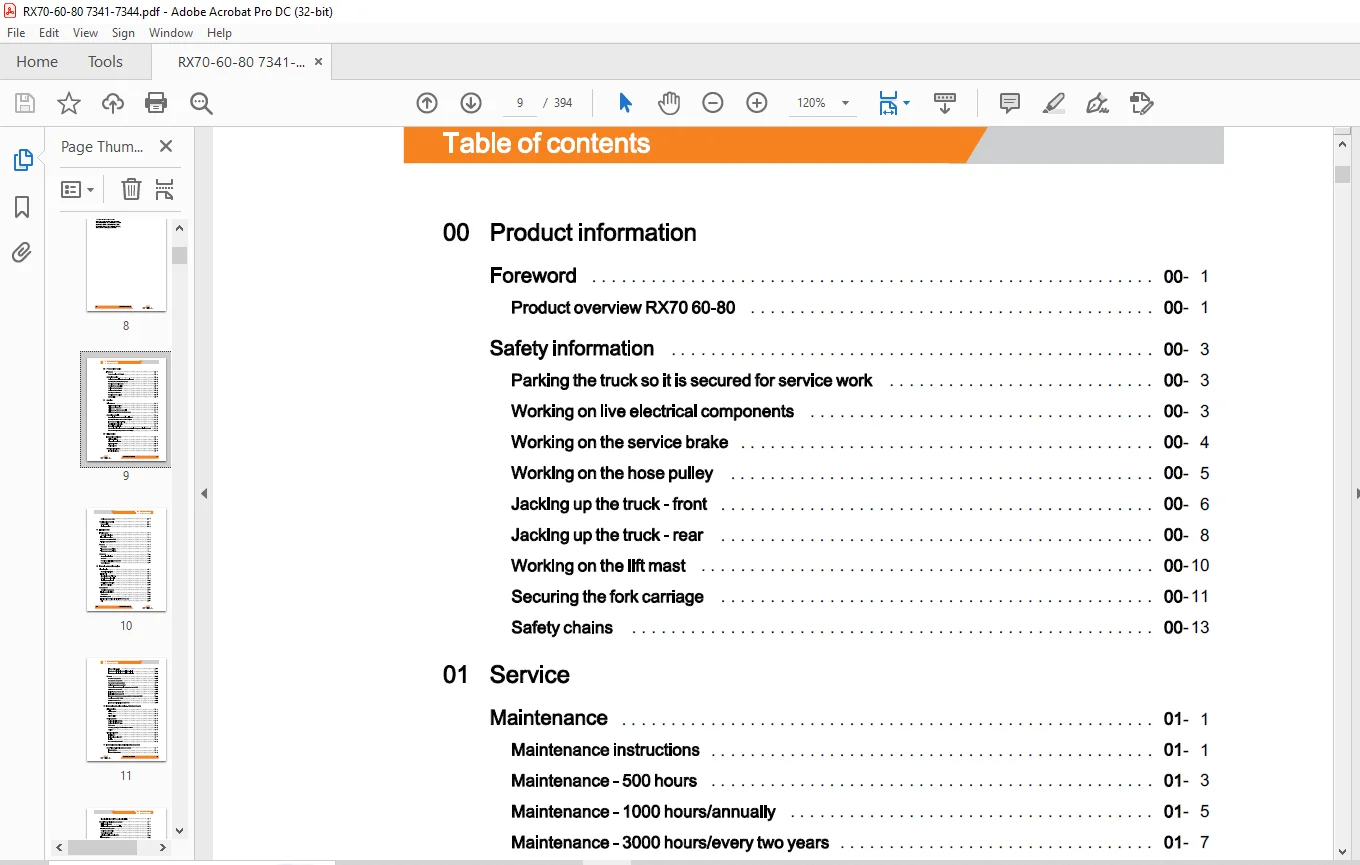
- 00 Product information
Foreword 00
Product overview RX70 60-80 00
Safety information 00
Parking the truck so it is secured for service work 00
Working on live electrical components 00
Working on the service brake 00
Working on the hose pulley 00
Jacking up the truck – front 00
Jacking up the truck – rear 00
Working on the lift mast 00
Securing the fork carriage 00
Safety chains 00
01 Service
Maintenance 01
Maintenance instructions 01
Maintenance – 500 hours 01
Maintenance – 1000 hours/annually 01
Maintenance – 3000 hours/every two years 01
Operating materials 01
Measuring instruments and testing equipment 01
Special tools for internal combustion engines 01
Harnesses and hoists, 6.0t- 8.0t 01
Special tools for drive axles 01
Hose pulley special tools 01
Standardised tightening torques for standard-pitch threads and fine-pitch threads 01
Standardised tightening torques for hose fittings 01
02 Diagnostics
Introduction to DiaMon 02
STEDS-Navigator 02
Diagnostics service box 02
Diagnostic set-up 02
Starting DiaMon 02
Working with DiaMon 02
Error list via DiaMon 02
STILL
VIII 57348012001 EN – 02/2019
Table of contents
Reading out access codes 02
Working using the ABE 02
Read error list 02
Clearing error lists 02
11 Electric motor
Traction motor 11
General technical data 11
Electrical connections 11
Traction motors (->09/2018) 11
Traction motors (09/2018->) 11
Sensors 11
Rev sensor 11
Temperature sensor KTY84 11
Temperature sensor PT1000 11
Generator 11
General technical data 11
Generator 11
Removing and installing the generator 11
Starter ring gear 11
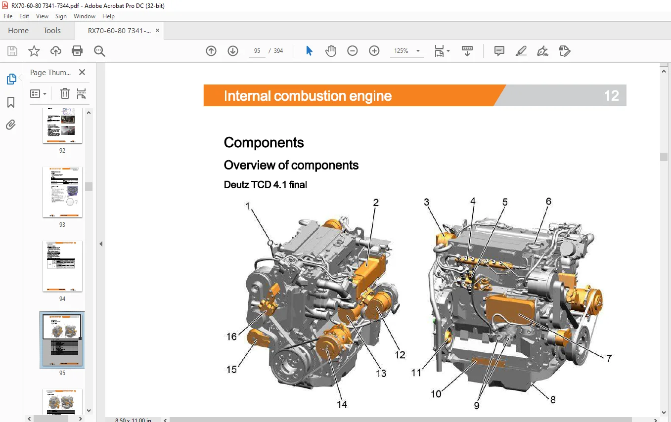
12 Internal combustion engine
Diesel engine 12
General technical data 12
Engine unit 12
Diesel engine Deutz TCD 4.1 12
Removing the engine unit 12
Installing the engine unit 12
Replacing the catch plate 12
Alternator monitoring 12
Components 12
Overview of components 12
Engine control unit ECU 12
Starter motor 12
Fuel delivery pump 12
Fuel quantity metering unit with high-pressure pumps 12
Rail 12
57348012001 EN – 02/2019 IX
Table of contents
Injector (CRIN 3.3-20) 12
Exhaust gas recirculation, Deutz TCD 4.1 final 12
Exhaust gas recirculation, Deutz TCD 4.1 interim 12
Sensors 12
Overview of the sensors 12
Camshaft rev sensor B401 12
Rev sensor for crankshaft B402 12
Coolant temperature sensor B43 12
Charge air pressure/charge air temperature sensor B48 12
Rail pressure sensor B49 12
Fuel low-pressure sensor B51 12
Engine oil pressure sensor B6 12
Exhaust gas back pressure sensor before the turbocharger 0B60 12
Venturi sensors 0B61, 0B64 12
MPROP actuator 0Y19 12
Exhaust gas recirculation actuator 0Y20 12
13 Internal combustion engine -Attachment parts
Air intake/filter 13
Air filter system 13
Air filter 13
Oil bath air filter 13
Cooling system 13
Cooling circuit (->09/2018) 13
Cooling circuit (09/2018->) 13
Water pump 13
Checking, topping up and bleeding the coolant 13
Coolant 13
Diesel fuel system 13
Fuel diagram 13
Fuel level transmitter6B3 13
Fuel filter 13
Low fuel warning threshold 13
14 Internal combustion engine- exhaust system
Deutz TCD 4.1 interim exhaust system 14
Exhaust system 14
Exhaust after-treatment 14
X 57348012001 EN – 02/2019
Table of contents
Diesel particle filter (DPF) Removal and installation 14
Deutz TCD 4.1 final exhaust system 14
DEF reduction agent 14
DEF reduction agent – correct refuelling 14
Flushing the SCR system 14
Continuous regeneration 14
Standstill regeneration 14
Selective catalytic reduction SCR 14
Exhaust system 14
DEFtank 14
DEF feed pump 14
SCR mixing section 14
Sensors in the SCR system 14
22 Mechanical drive axle
AE80-01 drive axle 22
General technical data 22
General technical data – pilot series 22
AE80-01 drive axle 22
Drive wheel unit 22
Removing the drive wheel unit and the multi-disc brake 22
Traction motor – Removing the rotor 22
Traction motor- Installing the rotor 22
Installing the drive wheel unit and the multi-disc brake 22
Replacing the bearing and sealing ring for the traction motor 22
Drive wheel unit – Replacing the sealing ring 22
Checking the oil level 22
Oil change 22
AE80-03 drive axle 22
General technical data 22
Drive axle AE80-03 (09/2018->) 22
30 Chassis, bodywork and fittings
Chassis 30
Working with gas springs 30
Counterweight 30
Counterweight 30
57348012001 EN – 02/2019 XI
Table of contents
42 Steering system
Hydraulic steering 42
General technical data 42
Steering system 42
Steering – error detection 42
Steering unit 42
Priority valve 42
Steering axle 42
General technical data 42
Swing axle 42
Steering angle sensor 3B02 42
Wheel hub 42
Steering angle 42
Tie rod 42
Axle stub 42
49 Brake system
Hydraulic operating brake 49
General technical data 49
Spring-operated brake 49
Brake valve 49
Accumulator charging section 49
50 Operating devices
Accelerator pedal 50
Accelerator pedal, generation 2 50
Accelerator- single-pedal 50
Accelerator- dual pedal, generation 2 50
Brake actuation 50
Brake actuation 50
Changing the brake cable 50
Brake sensor 1 B2 50
Parking brake switch 1 S3 50
Hydraulic actuation 50
Joystick 4Plus 50
Axle assignment – Joystick 4Plus 50
Generation 2 mini-lever 50
XII 57348012001 EN – 02/2019
Table of contents
Axle assignment – the mini-lever 50
Joystick 50
Axle assignment – Joystick 50
Tip switch 50
Axle assignment – fingertip switch 50
56 Display elements
Operating console 56
Turn indicator module for the drive direction, generation 2 56
Direction indicator module (Fabli) 56
Display 56
Display and operating unit, generation 2 (ABE 2) 56
ABE 2 Installation and removal 56
60 Electrics/electronics
General 60
General technical data 60
Overview of electrical components 60
Overview of the controllers 60
Software compatibility 60
PAN process 60
Parameter management 60
Error ring buffer 60
Traction motor temperature monitoring 60
Temperature monitoring for the traction converter 60
Availability of drive mode and driving behaviour 60
Driving mode – driving behaviour Description 60
Stopping on a slope 60
Blue-Q=IQ 60
Electrical checks 60
Intermediate circuit 60
Insulation measurement 60
Wiring 60
CAN bus system 60
CAN bus connections 60
Power cables 60
Maintenance guidelines for power cables 60
Repair – Contact elements 60
57348012001 EN – 02/2019 XIII
Table of contents
Electrical system 60
Fusebox 60
Fuses in the fuse box 60
Additional fuses 60
Relays in the fuse box 60
Additional relay 60
Additional electrical installation 60
Option Board 60
CAN-Power-Port (CPP) 60
CPP 1/CPP 3 60
CPP2B 60
Relay-Power-Port 60
64 Electronic controls
Truck control unit 64
Truck Control Unit 2 (TCU 2) 64
Truck Control! Unit (TCU) Removal and installation 64
Converter 64
Converter 64
L TI converter 64
SVAC converter 64
Removing/installing converters 64
Converting from L TI to SVAC 64
Brake resistor 64
69 Batteries and accessories
Starter battery 69
Starter battery G1 69
Working with batteries 69
70 Hydraulics
General 70
General technical data 70
Depressurising the hydraulics 70
Lifting operating speeds 70
Lowering operating speeds 70
Tilt operating speeds 70
. . . . . . . . . . . . . . . . . . . . . . . . . . . . . . . -24
XIV 57348012001 EN – 02/2019
Table of contents
Safety check 70
Forward tilt safety test 70
Lowering safety test 70
Safety checks of hose assembly 70
Basic hydraulics 70
Basic hydraulics 70
Fan control valve 70
Steering hydraulics 70
Working hydraulics 70
Variable displacement pump 70
Pump regulator 70
Removing/installing the variable displacement pump 70
Hydraulic tank 70
Changing the hydraulic oil 70
Intake filter 70
Return filter 70
Breather 70
High-pressure filter 70
Bolted joint 70
Conical nipple fittings (CNF) 70
71 Working hydraulics
Tilt cylinder 71
Removing/installing the tilt cylinder 71
Changing the set of seals 6000 – 8000 kg 71
Truck auxiliary hydraulics 71
Operating speeds of the attachments 71
Second operating function for attachments 71
Clamp locking mechanism with servo hydraulics 71
Accumulator 71
Accumulator 71
Checking the accumulator 71
Hose pulley 71
Hose pulley 71
Removing/installing the hose pulley 71
Releasing and adjusting the tension of the hose pulley 71
Changing the set of seals in the hose pulley 71
57348012001 EN – 02/2019 XV
Table of contents
Changing the hose line on the four-way hose reel 71
Changing the seals in the swivel joint 71
76 Valves
Servo hydraulics 76
General technical data 76
Directional control valve block 76
Removing/installing the valve block 76
80 Load lift system
Mast bearing 80
Mast bearings AE80-01, AE80-02 80
81 Lift mast
Lift mast 81
General technical data 81
Line break safety valve 81
Support roller play ( 195) 81
Load chains – Checking and cleaning 81
Working on lift masts 81
Removing the lift mast 81
Installing the lift mast 81
Telescopic lift mast 81
Telescopic lift mast ( 195) 81
Telescopic lift mast (195) load chain adjustment 81
Triplex lift mast 81
Triplex lift mast ( 195) 81
Triplex lift mast ( 195) load chain adjustment 81
Lift cylinder 81
Working on lift cylinders 81
Removing/installing outer cylinders 81
Removing and installing the centre cylinder 81
End position damping location 81
End position damping, type A (top) 81
End position damping, type B (bottom) 81
Annex
X Circuit diagrams
Hydraulics
Servo hydraulics - Contact us: [email protected]
- PLEASE NOTE:
- This is the same manual used by the DEALERSHIPS to SERVICE your vehicle.
- The manual can be all yours – Once payment is complete, you will be taken to the download page from where you can download the manual. All in 2-5 minutes time!!
- Need any other service / repair / parts manual, please feel free to contact us at heydownloadss @gmail.com . We may surprise you with a nice offer
- S.M