Trusted Business
Verified & Licensed
Virus Free Files
100% Safe Downloads
Secure Payment
SSL Protected
Instant Delivery
Available Immediately
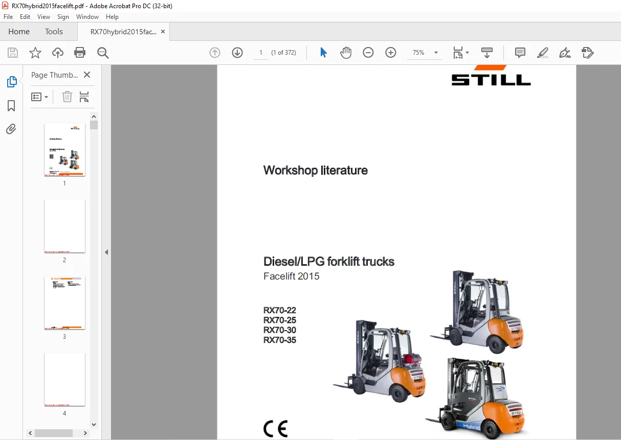
STILL STED Diesel LPG forklift trucks Facelift 2015 RX70-22 RX70-25 RX70-30 RX70-35 Workshop Manual – PDF DOWNLOAD
$28.95
STILL STED Diesel LPG forklift trucks Facelift 2015 RX70-22 RX70-25 RX70-30 RX70-35 Workshop Manual – PDF DOWNLOAD
Instant PDF Download
Available immediately
Save to Your Device
Download & keep forever
Antivirus Scanned
100% virus-free
Trusted Worldwide
175,000+ customers
Description
STILL STED Diesel LPG forklift trucks Facelift 2015 RX70-22 RX70-25 RX70-30 RX70-35 Workshop Manual – PDF DOWNLOAD
FILE DETAILS:
STILL STED Diesel LPG forklift trucks Facelift 2015 RX70-22 RX70-25 RX70-30 RX70-35 Workshop Manual – PDF DOWNLOAD
Language : English
Pages : 372
Downloadable : Yes
File Type : PDF
DESCRIPTION:
STILL STED Diesel LPG forklift trucks Facelift 2015 RX70-22 RX70-25 RX70-30 RX70-35 Workshop Manual – PDF DOWNLOAD
Special features of the RX70 Facelift 2015
- The enhancement of the Hybrid II technology in the load capacity class 3.0 t-3.5 t allows for a high level of performance at a lower consumption level.
- The less powerful yet cost-effective DSO variant is also offered in the same load capacity class but without Hybrid components.
- The LPG trucks all feature the latest version of the LPG system.
Facelift 2015
• New MaLis lift mast Modified drive axle and mast bearing SVAC converter with a dedicated water cooler Impco LPG system with C-series evaporator (regulated and unregulated)
• Only servo hydraulics; no hand lever
• Joystick 4Plus operating device
• Electrically adjustable variable displacement pump
Modified wiring; adaption in line with the RX series . Diagnostic connector in the front structure CPP2b (lighting) Hybrid II Performance-enhanced drive unit Performance-enhanced hydraulics (for lifting)
Coasting mode
IMAGES PREVIEW OF THE MANUAL:
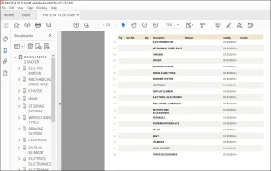
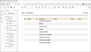
TABLE OF CONTENTS:
STILL STED Diesel LPG forklift trucks Facelift 2015 RX70-22 RX70-25 RX70-30 RX70-35 Workshop Manual – PDF DOWNLOAD
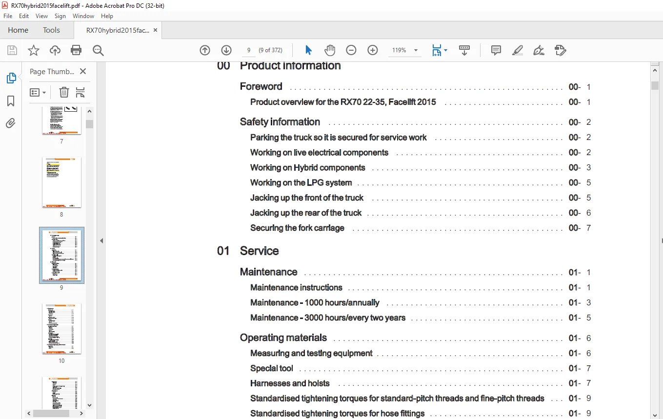
00 Product information
Foreword 00- 1
Product overview for the RX70 22-35, Facelift2015 00- 1
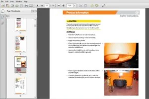
Safety information 00- 2
Parking the truck soitis secured for servicework 00- 2
Working on live electricalcomponents LL 00- 2
WorkingonHybridcomponents 00- 3
Workingonthe LPGsystem 00- 5
Jackingupthefrontofthetruck iL 00- 5
Jackinguptherearofthetruck iL 00- 6
Securing theforkcarriage 00- 7
01 Service
Maintenance 01-1
Maintenance instructions LL 01-1
Maintenance -1000 hours/annually 01- 3
Maintenance – 3000 hours/everytwoyears 01-5
Operatingmaterials 01- 6
Measuringandtestingequipment 01- 6
Specialtool 01-7
Harnessesand hoists 01- 7
Standardised tightening torques for standard-pitch threads and fine-pitch threads 01- 9
Standardised tightening torques for hose fittings 01- 9
Product overview for the RX70 22-35, Facelift2015 00- 1
Safety information 00- 2
Parking the truck soitis secured for servicework 00- 2
Working on live electricalcomponents LL 00- 2
WorkingonHybridcomponents 00- 3
Workingonthe LPGsystem 00- 5
Jackingupthefrontofthetruck iL 00- 5
Jackinguptherearofthetruck iL 00- 6
Securing theforkcarriage 00- 7
01 Service
Maintenance 01-1
Maintenance instructions LL 01-1
Maintenance -1000 hours/annually 01- 3
Maintenance – 3000 hours/everytwoyears 01-5
Operatingmaterials 01- 6
Measuringandtestingequipment 01- 6
Specialtool 01-7
Harnessesand hoists 01- 7
Standardised tightening torques for standard-pitch threads and fine-pitch threads 01- 9
Standardised tightening torques for hose fittings 01- 9
02 Diagnostics
IntroductiontoDiaMon 02- 1
STEDS-Navigator 02- 1
CANboxdiagnostics 02- 2
Diagnosticset-up 02- 3
Starting DiaMon 02- 4
STEDS-Navigator 02- 1
CANboxdiagnostics 02- 2
Diagnosticset-up 02- 3
Starting DiaMon 02- 4
WorkingwithDiaMon 02- 5
Reading outand clearingtheerrorlist 02- 5
Readingoutaccesscodes 02- 6
Reading outand clearingtheerrorlist 02- 5
Readingoutaccesscodes 02- 6
Workingusingthe ABE 02- 7
Readerrorlist 02- 7
Clearingerrorlists 02- 9
Readerrorlist 02- 7
Clearingerrorlists 02- 9
11 Electric motor
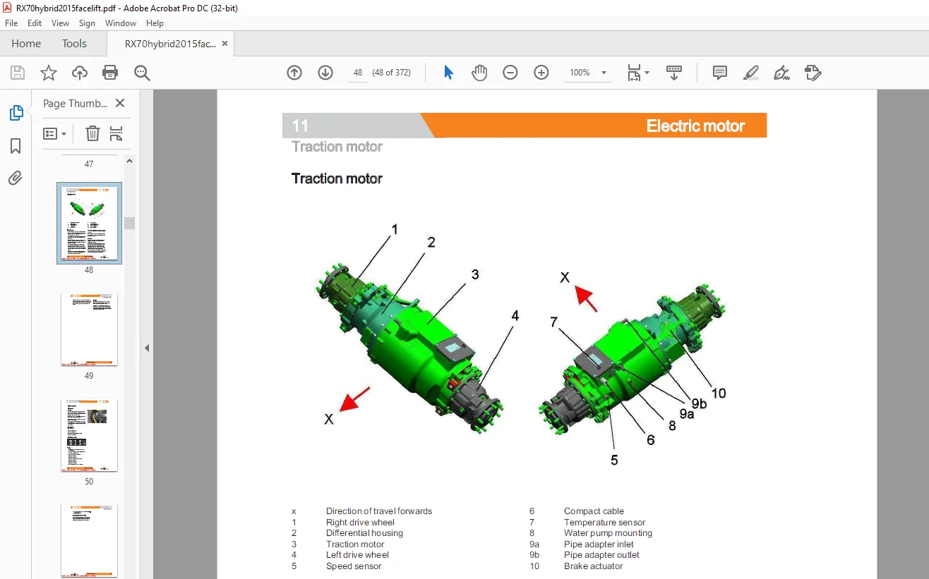
Tractionmotor 11-1
Generaltechnicaldata 11-1
Electricalconnections 11-1
Traction motor 1- 2
Generaltechnicaldata 11-1
Electricalconnections 11-1
Traction motor 1- 2
Speed sensor 11- 4
Pin Sensor 11- 4
Pin Sensor 11- 4
Temperature SeNSOr 11- 6
Temperature sensor KTY84 11- 6
Temperature sensor KTY84 11- 6
Generator 11- 8
Generaltechnicaldata 11- 8
Alternator 11-9
Alternator removal-installation 11-10
Generaltechnicaldata 11- 8
Alternator 11-9
Alternator removal-installation 11-10
12 Internal combustion engine
Internal combustionengine LL 12- 1
Engineunit 12- 1
Startermotor 12- 2
Starterringgear LL 12- 2
Alternator 12- 3
Alternatormonitoring 12- 4
Engineunit 12- 1
Startermotor 12- 2
Starterringgear LL 12- 2
Alternator 12- 3
Alternatormonitoring 12- 4
Dieselengine 12- 6
General technicaldata VW 1 91SDI 12- 6
Dieselengine VW 1 9ISDI/TDI 12- 7
Engine control unit VW 1 9ISDI/TDI 12- 8
Removing and installingthe engine unit 12-10
General technicaldata VW 1 91SDI 12- 6
Dieselengine VW 1 9ISDI/TDI 12- 7
Engine control unit VW 1 9ISDI/TDI 12- 8
Removing and installingthe engine unit 12-10
LPGengine 12-16
General technical data VW 2 01SPI 12-16
VWLPG-20litre BEF 12-18
Engine controlunitVW2 01SPI 12-19
Removing and installingthe engine unit 12-20
General technical data VW 2 01SPI 12-16
VWLPG-20litre BEF 12-18
Engine controlunitVW2 01SPI 12-19
Removing and installingthe engine unit 12-20
13 Internal combustion engine – Attachment parts
Airintakeffilter 13- 1
Airfiltersystem 13- 1
Airfilter 13- 2
Airfiltersystem 13- 1
Airfilter 13- 2
_ THN
STILL
STILL
TRIAL MODE – a valid license will remove this message See the keywords property of this PDF for more information
Table of contents
Table of contents
Cooling system 13- 3
Coolingcircuit 13- 3
Waterpump 13- 5
Coolant 13- 6
Checking, topping up and changing thecoolant 13- 7
Radiatorsystem 13- 9
Radiator Removal and installation 13-10
Fanwheelrotor-fanmotor 13-11
Coolingcircuit 13- 3
Waterpump 13- 5
Coolant 13- 6
Checking, topping up and changing thecoolant 13- 7
Radiatorsystem 13- 9
Radiator Removal and installation 13-10
Fanwheelrotor-fanmotor 13-11
Dieselfuelsystem 13-14
Fuelsystem 13-14
Fuelfilter 13-15
Lowfuelwarningthreshold 13-15
Fuelsystem 13-14
Fuelfilter 13-15
Lowfuelwarningthreshold 13-15
LPGsystem 13-17
LPG system 13-17
Evaporatormodule 13-19
Removing and installing the evaporator 13-20
Suctionmodule 13-21
MAP/MAT sensor0B6 13-22
Actuatorunit 13-23
Gas shut-off valvemonitoring 13-23
Shut-downduetolackofgas 13-25
Maintenance and test specifications 13-26
Testing forleaksinthe LPGsystem 13-27
Testing CO levelinexhaustgases 13-28
Servicingthe LPGfilter 13-30
Servicing the 30-bar high-pressure reliefvalve 13-31
14 Internal combustion engine – Exhaust system
Exhaustsystem-Diesel 14- 1
Exhaustsystem 14- 1
Exhaust system – Particlefilter 14- 2
General technical data-Eberspacher 14- 2
Structure of the Eberspécher particlefilter 14- 3
7 5kW Eberspéacher particlefilter 14- 3
Regeneration LL 14- 6
Maintenance instructions 14- 8
Exhaustsystem 14- 1
Exhaust system – Particlefilter 14- 2
General technical data-Eberspacher 14- 2
Structure of the Eberspécher particlefilter 14- 3
7 5kW Eberspéacher particlefilter 14- 3
Regeneration LL 14- 6
Maintenance instructions 14- 8
Table of contents
Exhaustsystem-LPG 14- 9
Exhaustsystem 14- 9
Lambdacontrolsystem LL 14-10
Lambda sensor 14-11
Three-way catalyticconverter 14-13
Exhaustsystem 14- 9
Lambdacontrolsystem LL 14-10
Lambda sensor 14-11
Three-way catalyticconverter 14-13
Mechanical drive axle
Driveaxle 8 30 22- 1
General technical data, Carraro 8 30 22- 1
Drive axle 22- 2
Wheeldrive 22- 3
Removal and installation of the driveaxle 22- 5
Traction motor 22- 8
Servicebrake LL 22-10
Differential gearbox 22-13
General technical data, Carraro 8 30 22- 1
Drive axle 22- 2
Wheeldrive 22- 3
Removal and installation of the driveaxle 22- 5
Traction motor 22- 8
Servicebrake LL 22-10
Differential gearbox 22-13
Chassis
Chassis 31- 1
Floorplate 31-1
Floorplate 31-1
Counterweight 31- 2
Counterweight 31- 2
Counterweight 31- 2
Steering system
Hydraulicsteering 42- 1
Generaltechnicaldata 42- 1
Steeringsystem 42- 2
Steering—errordetection 42- 3
Steering unit 42- 3
Priority valve 42- 4
Generaltechnicaldata 42- 1
Steeringsystem 42- 2
Steering—errordetection 42- 3
Steering unit 42- 3
Priority valve 42- 4
Steering wheel and steeringcolumn 42- 5
Steering column LLL 42- 5
Steering column LLL 42- 5
Steeringaxle 42-9
Generaltechnicaldata 42- 9
Swingaxle 42-10
Swing axle Removal and installation 42-11
Wheelhub 42-13
Steeringangle 42-15
Generaltechnicaldata 42- 9
Swingaxle 42-10
Swing axle Removal and installation 42-11
Wheelhub 42-13
Steeringangle 42-15
49 Brake system
Hydraulicoperatingbrake iL 49- 1
Brakesensor1B2 LL 49- 1
Parkingbrake 49- 2
Replacingthebrakecable 49- 2
Actuating force ofthehandbrake 49- 2
Parking brake switch1S3 49- 3
Brakesensor1B2 LL 49- 1
Parkingbrake 49- 2
Replacingthebrakecable 49- 2
Actuating force ofthehandbrake 49- 2
Parking brake switch1S3 49- 3
50 Operating devices
Singlepedal 50- 1
Accelerator—single-pedal 50- 1
Dualpedal 50- 4
Accelerator—dualpedal 50- 4
Operatingdevices 50- 7
Joystick 4PIus oo 50- 7
Axle assignment -Joystick4Plus 50- 8
Generation2mini-lever LL 50-10
Axle assignment-themini-lever 50-12
Tipswitch Lo 50-14
Axle assignment-fingertipswitch 50-15
Accelerator—single-pedal 50- 1
Dualpedal 50- 4
Accelerator—dualpedal 50- 4
Operatingdevices 50- 7
Joystick 4PIus oo 50- 7
Axle assignment -Joystick4Plus 50- 8
Generation2mini-lever LL 50-10
Axle assignment-themini-lever 50-12
Tipswitch Lo 50-14
Axle assignment-fingertipswitch 50-15
56 Display elements
Operatingconsole 56- 1
Direction indicatormodule (Fabli) 56- 1
Display 56- 3
Display and operating unit, generation2 (ABE 2) 56- 3
ABE 2Installationandremoval 56- 4
Direction indicatormodule (Fabli) 56- 1
Display 56- 3
Display and operating unit, generation2 (ABE 2) 56- 3
ABE 2Installationandremoval 56- 4
60 Electrical enclosure
General 60- 1
Generaltechnicaldata 60- 1
Overviewofthecontrollers 60- 2
Overview of electricalcomponents 60- 3
Software compatibility 60- 4
PANDroCess 60- 5
Parametermanagement LLL 60- 6
Generaltechnicaldata 60- 1
Overviewofthecontrollers 60- 2
Overview of electricalcomponents 60- 3
Software compatibility 60- 4
PANDroCess 60- 5
Parametermanagement LLL 60- 6
Errorringbuffer
Intermediatecircuit
Insulation measurement LL
Hybrid component insulation measurements
Traction motor temperature monitoring
Temperature monitoring for the tractionconverter
Drive mode — driving behaviour Availability
Driving mode — driving behaviour Description
Blue-Q=1Q
Intermediatecircuit
Insulation measurement LL
Hybrid component insulation measurements
Traction motor temperature monitoring
Temperature monitoring for the tractionconverter
Drive mode — driving behaviour Availability
Driving mode — driving behaviour Description
Blue-Q=1Q
WING
CANbussystem
CANbusconnections
Powercables
Maintenance guidelines forpowercables
CANbussystem
CANbusconnections
Powercables
Maintenance guidelines forpowercables
Repair-Contactelements
Electrical system L
Fusebox
Fusesinthefusebox
Fusebox
Fusesinthefusebox
Relaysinthefusebox
Sensorsystem
Vertical lift mast position iL
Tiltanglesensor7B46 i
Tiltangle sensorparameters
Installation of the vertical lift mast position
Loadmeasurement i
Vertical lift mast position iL
Tiltanglesensor7B46 i
Tiltangle sensorparameters
Installation of the vertical lift mast position
Loadmeasurement i
Load measurement pressure Sensor LL
Additional electrical installation
OptionBoard
CAN-Power-Port (CPP)
CPP1/CPP 3
OptionBoard
CAN-Power-Port (CPP)
CPP1/CPP 3
SootCPP(CPP5)
Relay-Power-Port
Relay-Power-Port
64 Electronic controls
Truckcontrolunit i
Truck Control Unit2(TCU2)
Truck Control Unit2(TCU2)
TRIAL MODE – a valid license will remove this message See the keywords property of this PDF for more information
Table of contents
Table of contents
Truck Controll Unit (TCU) Removal and installation 64- 2
Converter 64- 4
SVAC converter 64- 4
SVACHybridllconverter 64- 5
Removing and installingthe converter 64- 6
Brakeresistor LLL 64- 9
Hybridcomponents 64-11
Hybrid lIfunction 64-11
Functional test for hybridsystems 64-12
DC/DC GONVEMEr o oo 64-12
DC/DC converter Removal and installation 64-14
Storage module —energy accumulators LL 64-16
Storage module Removal andinstallation 64-18
Forcedventilation 64-19
69 Batteries and accessories
Starterbattery 69- 1
Starterbattery 69- 1
Starterbattery 69- 1
70 Hydraulics
General 70- 1
Generaltechnicaldata 70- 1
Releasing the pressure from the hydraulics 70- 3
Tiltoperatingspeeds 70- 3
Operating speeds forlifting 70- 4
Operating speeds forlowering 70- 5
Generaltechnicaldata 70- 1
Releasing the pressure from the hydraulics 70- 3
Tiltoperatingspeeds 70- 3
Operating speeds forlifting 70- 4
Operating speeds forlowering 70- 5
Safetycheck 70- 6
Forwardftiltsafetytest 70- 6
Loweringsafetytest 70- 6
Safety checks ofhoseassembly iL 70- 7
Forwardftiltsafetytest 70- 6
Loweringsafetytest 70- 6
Safety checks ofhoseassembly iL 70- 7
Basichydraulics 70- 8
Basichydraulics 70- 8
Fanmotorcontrolunit 70-10
Fancontrolvalve 70-11
Steering hydraulics 70-13
Operating hydraulics 70-14
Variable displacementpump 70-16
Basichydraulics 70- 8
Fanmotorcontrolunit 70-10
Fancontrolvalve 70-11
Steering hydraulics 70-13
Operating hydraulics 70-14
Variable displacementpump 70-16
oT AE
STILL
STILL
TRIAL MODE – a valid license will remove this message See the keywords property of this PDF for more information
Table of contents
Table of contents
TRIAL MODE – a valid license will remove this message See the keywords property of this PDF for more information
Hybrid variable displacementpump 70-18
Pumpregulator 70-19
Variable pumpRemoval and installation 70-20
Hydraulictank 70-22
Hydraulicoil 70-23
Returnfilter 70-24
Breather 70-25
Intakefilter 70-26
High-pressurefilter 70-26
Conical nipple fittings (CNF) 70-27
Bolted joint 70-27
71 Working hydraulics
Tilteylinder 71-1
Masttilt 71-1
Tilt cylinder Removal and installation 71-1
Changing the set of seals2200-5000 kg-LSP 500 71- 2
Auxiliary hydraulics 71- 5
Attachments 71- 5
Second operating function forattachments 71-7
76 Valves
Servohydraulics 76- 1
Generaltechnicaldata 76- 1
Directional control valve block 76- 2
Directional control valve function Lifting 76- 4
Directional control valve function Lowering 76- 6
80 Load lift system
Mastbearings LL 80- 1
Carraro MalLismastbearing 80- 1
81 Lift mast
Liftmast 81- 1
Generaltechnicaldata 81- 1
Hose safety valve of triplexmast 81- 2
Supportroller play (108/117/130) 81- 5
Load chains – Checkingandcleaning 81- 6
Run-outbarrier 81- 8
Workingonliftmasts 81- 9
Lift mast-Removal 81- 9
Lift mast-Installation 81-10
Telescopicliftmast 81-13
Telescopic liftmast(130MaLiS) 81-13
Adjusting the load chains Telescopic liftmast{(130MaLiS) 81-14
Removing the supportrollersintheliftmast 81-15
Assembling the lift mast after replacing the supportrollers 81-16
Outer load chains and chainrollers 81-17
NiHoliftmast 81-19
NiHoliftmast (130 MaLiS) 81-19
Adjusting the load chains NiHo lift mast (130MaLiS) 81-21
Triplexliftmast 81-22
Tripleliftmast(130MaLiS) 81-22
Adjusting the outer load chains Triple lift mast (130MaLiS) 81-24
Adjusting the middle load chain Triple lift mast (130MaLiS) 81-25
Removing the supportrollers 81-26
Assembling the lift mast after replacing the supportrollers 81-29
Outer load chainsandchainrollers 81-31
Middle load chainand chainroller 81-33
Lifteylinder 81-35
Liftjack 81-35
Working onliftcylinders 81-36
Removing and installing the outercylinders 81-36
Disassembling/assembling the outercylinder 81-41
Middlecylinder 81-44
Disassembling/assembling the middle cylinder 81-45
End position damping of outercylinder 81-48
Middle cylinder end dampener 81-49
Contact us: [email protected]
https://vimeo.com/854278926?share=copy
PLEASE NOTE:
- This is the SAME exact manual used by your dealers to fix your vehicle.
- The same can be yours in the next 2-3 mins as you will be directed to the download page immediately after paying for the manual.
- Any queries / doubts regarding your purchase, please feel free to contact [email protected]
S.M