Still STED Diesel LPG forklift trucks Facelift 2015 RX70-22 RX70-25 RX70-30 RX70-35 Workshop Manual – PDF DOWNLOAD
$28.95
Still STED Diesel LPG forklift trucks Facelift 2015 RX70-22 RX70-25 RX70-30 RX70-35 Workshop Manual – PDF DOWNLOAD
Description
Still STED Diesel LPG forklift trucks Facelift 2015 RX70-22 RX70-25 RX70-30 RX70-35 Workshop Manual – PDF DOWNLOAD
FILE DETAILS:
Still STED Diesel LPG forklift trucks Facelift 2015 RX70-22 RX70-25 RX70-30 RX70-35 Workshop Manual – PDF DOWNLOAD
Language : English
Pages :
Downloadable : Yes
File Type : PDF
DESCRIPTION:
Still STED Diesel LPG forklift trucks Facelift 2015 RX70-22 RX70-25 RX70-30 RX70-35 Workshop Manual – PDF DOWNLOAD
Documentation
This workshop manual contains all the informa- tion required to assist qualified service engineers with all work, repairs and maintenance performed on this truck. In addition, some of the components have been deliberately excluded from this workshop manual and are explained elsewhere to ensure a clear and complete overview. These components are explained in workshop manuals, special documentation and circuit diagrams. Changes may be made at short notice and at any time, and are communicated via service information documents.
- • LPG trucks RX70 22-35
- • Diesel trucks RX70 22-35
- FleetManager TM 4.X
- Error list
- Overview of truck software
- Overview of consumables
- STILL flasher
- FEM 4.004 test log book
- Service information documents
IMAGES PREVIEW OF THE MANUAL:
TABLE OF CONTENTS:
Still STED Diesel LPG forklift trucks Facelift 2015 RX70-22 RX70-25 RX70-30 RX70-35 Workshop Manual – PDF DOWNLOAD
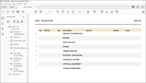
Product overview for the RX70 22-35, Facelift2015 00- 1
Safetyinformation 00- 2
Parking the truck so itis secured for servicework 00- 2
Working on live electricalcomponents LL 00- 2
WorkingonHybridcomponents 00- 3
Workingonthe LPGsystem 00- 5
Jackingupthefrontofthetruck iL 00- 5
Jackinguptherearofthetruck iL 00- 6
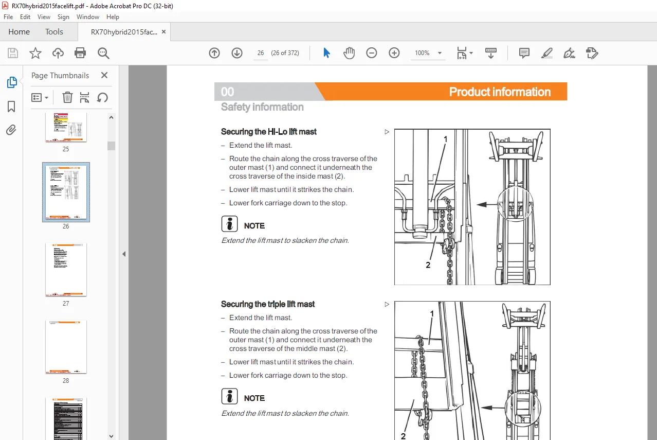
Securing theforkcarriage 00- 7
01 Service
Maintenance 01-1
Maintenanceinstructions LL 01-1
Maintenance -1000 hours/annually 01- 3
Maintenance – 3000 hours/everytwoyears 01-5
Operatingmaterials 01- 6
Measuringandtestingequipment 01- 6
Specialtool 01-7
Harnessesand hoists 01- 7
Standardised tightening torques for standard-pitch threads and fine-pitch threads 01- 9
Standardised tightening torques for hose fittings 01- 9
STEDS-Navigator 02- 1
CANboxdiagnostics 02- 2
Diagnosticset-up 02- 3
Starting DiaMon 02- 4
Reading outand clearingtheerrorlist 02- 5
Readingoutaccesscodes 02- 6
Readerrorlist 02- 7
Clearingerrorlists 02- 9
Generaltechnicaldata 11-1
Electricalconnections 11-1
Traction motor 1- 2
Pin Sensor 11- 4
Temperature sensor KTY84 11- 6
Generaltechnicaldata 11- 8
Alternator 11-9
Alternator removal-installation 11-10
Engineunit 12- 1
Startermotor 12- 2
Starterringgear LL 12- 2
Alternator 12- 3
Alternatormonitoring 12- 4
General technicaldata VW 1 91SDI 12- 6
Dieselengine VW 1 9ISDI/TDI 12- 7
Engine control unit VW 1 9ISDI/TDI 12- 8
Removing and installingthe engine unit 12-10
General technical data VW 2 01SPI 12-16
VWLPG-20litre BEF 12-18
Engine controlunitVW2 01SPI 12-19
Removing and installingthe engine unit 12-20
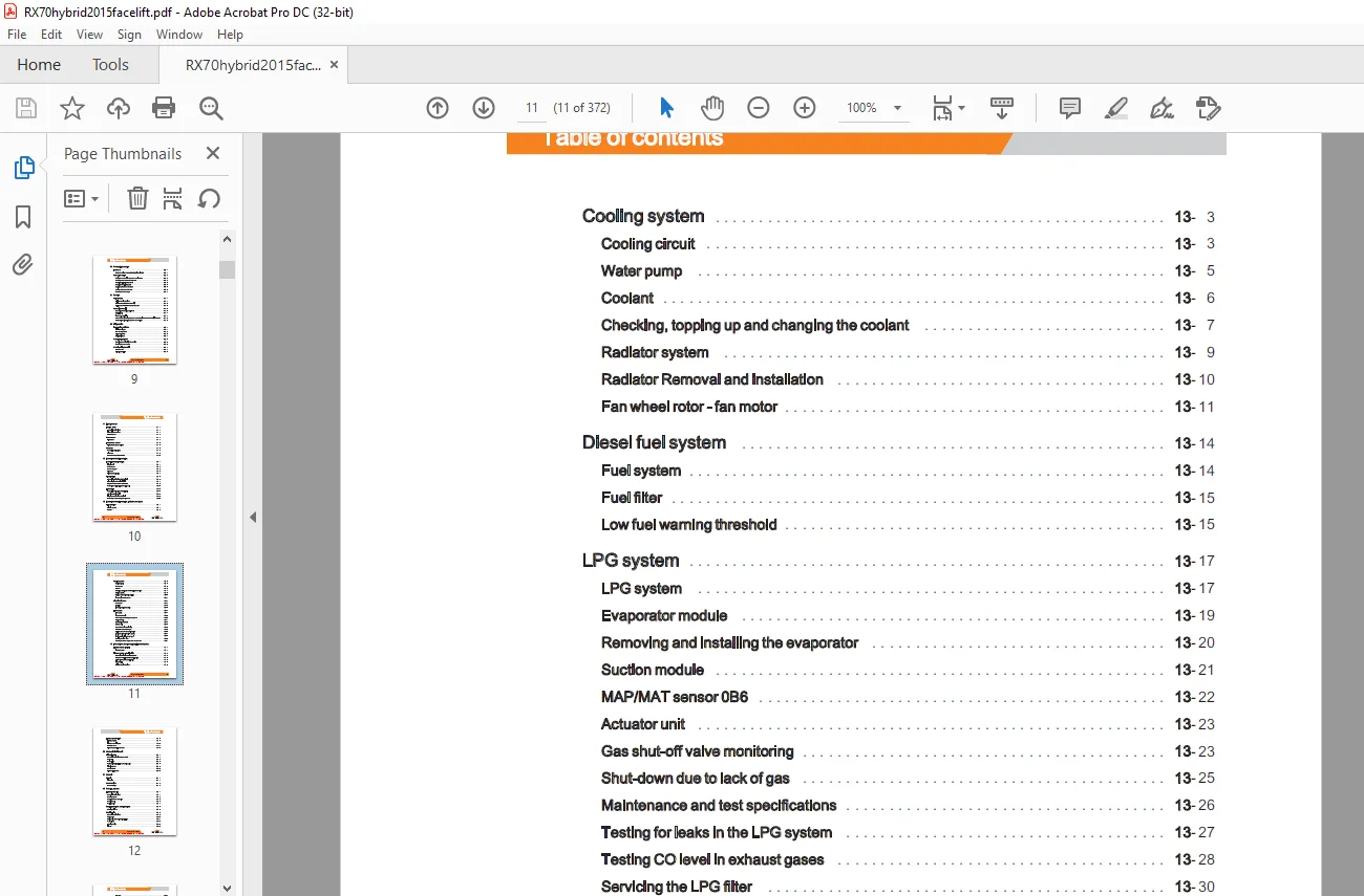
Airfiltersystem 13- 1
Airfilter 13- 2
Coolingcircuit 13- 3
Waterpump 13- 5
Coolant 13- 6
Checking, topping up and changing thecoolant 13- 7
Radiatorsystem 13- 9
Radiator Removal and installation 13-10
Fanwheelrotor-fanmotor 13-11
Fuelsystem 13-14
Fuelfilter 13-15
Lowfuelwarningthreshold 13-15
LPG system 13-17
Evaporatormodule 13-19
Removing and installing the evaporator 13-20
Suctionmodule 13-21
MAP/MAT sensor0B6 13-22
Actuatorunit 13-23
Gas shut-off valvemonitoring 13-23
Shut-downduetolackofgas 13-25
Maintenance and test specifications 13-26
Testing forleaksinthe LPGsystem 13-27
Testing CO levelinexhaustgases 13-28
Servicingthe LPGfilter 13-30
Servicing the 30-bar high-pressure reliefvalve 13-31
Exhaustsystem 14- 1
Exhaust system – Particlefilter 14- 2
General technical data-Eberspacher 14- 2
Structure of the Eberspécher particlefilter 14- 3
7 5kW Eberspéacher particlefilter 14- 3
Regeneration LL 14- 6
Maintenance instructions 14- 8
Exhaustsystem 14- 9
Lambdacontrolsystem LL 14-10
Lambda sensor 14-11
Three-way catalyticconverter 14-13
General technical data, Carraro 8 30 22- 1
Drive axle 22- 2
Wheeldrive 22- 3
Removal and installation of the driveaxle 22- 5
Traction motor 22- 8
Servicebrake LL 22-10
Differential gearbox 22-13
Floorplate 31-1
Counterweight 31- 2
Generaltechnicaldata 42- 1
Steeringsystem 42- 2
Steering—errordetection 42- 3
Steering unit 42- 3
Priority valve 42- 4
Steering column LLL 42- 5
Generaltechnicaldata 42- 9
Swingaxle 42-10
Swing axle Removal and installation 42-11
Wheelhub 42-13
Steeringangle 42-15
Tie rod oo 42-16
Brakesensor1B2 LL 49- 1
Parkingbrake 49- 2
Replacingthebrakecable 49- 2
Actuating force ofthehandbrake 49- 2
Parking brake switch1S3 49- 3
Accelerator—single-pedal 50- 1
Dualpedal 50- 4
Accelerator—dualpedal 50- 4
Operatingdevices 50- 7
Joystick 4PIus oo 50- 7
Axle assignment -Joystick4Plus 50- 8
Generation2mini-lever LL 50-10
Axle assignment-themini-lever 50-12
Tipswitch Lo 50-14
Axle assignment-fingertipswitch 50-15
Direction indicatormodule (Fabli) 56- 1
Display 56- 3
Display and operating unit, generation2 (ABE 2) 56- 3
ABE 2Installationandremoval 56- 4
Generaltechnicaldata 60- 1
Overviewofthecontrollers 60- 2
Overview of electricalcomponents 60- 3
Software compatibility 60- 4
PANDroCess 60- 5
Parametermanagement LLL 60- 6
Intermediatecircuit
Insulation measurement LL
Hybrid component insulation measurements
Traction motor temperature monitoring
Temperature monitoring for the tractionconverter
Drive mode — driving behaviour Availability
Driving mode — driving behaviour Description
Blue-Q=1Q
CANbussystem
CANbusconnections
Powercables
Maintenance guidelines forpowercables
Fusebox
Fusesinthefusebox
Vertical lift mast position iL
Tiltanglesensor7B46 i
Tiltangle sensorparameters
Installation of the vertical lift mast position
Loadmeasurement i
OptionBoard
CAN-Power-Port (CPP)
CPP1/CPP 3
Relay-Power-Port
Truck Control Unit2(TCU2)
Converter 64- 4
SVAC converter 64- 4
SVACHybridllconverter 64- 5
Removing and installingthe converter 64- 6
Brakeresistor LLL 64- 9
Hybridcomponents 64-11
Hybrid lIfunction 64-11
Functional test for hybridsystems 64-12
DC/DC GONVEMEr o oo 64-12
DC/DC converter Removal and installation 64-14
Storage module —energy accumulators LL 64-16
Storage module Removal andinstallation 64-18
Forcedventilation 64-19
Starterbattery 69- 1
Generaltechnicaldata 70- 1
Releasing the pressure from the hydraulics 70- 3
Tiltoperatingspeeds 70- 3
Operating speeds forlifting 70- 4
Operating speeds forlowering 70- 5
Forwardftiltsafetytest 70- 6
Loweringsafetytest 70- 6
Safety checks ofhoseassembly iL 70- 7
Basichydraulics 70- 8
Fanmotorcontrolunit 70-10
Fancontrolvalve 70-11
Steering hydraulics 70-13
Operating hydraulics 70-14
Variable displacementpump 70-16
Pumpregulator 70-19
Variable pumpRemoval and installation 70-20
Hydraulictank 70-22
Hydraulicoil 70-23
Returnfilter 70-24
Breather 70-25
Intakefilter 70-26
High-pressurefilter 70-26
Conical nipple fittings (CNF) 70-27
Bolted joint 70-27
71 Working hydraulics
Tilteylinder 71-1
Masttilt 71-1
Tilt cylinder Removal and installation 71-1
Changing the set of seals2200-5000 kg-LSP 500 71- 2
Auxiliary hydraulics 71- 5
Attachments 71- 5
Second operating function forattachments 71-7
76 Valves
Servohydraulics 76- 1
Generaltechnicaldata 76- 1
Directional control valve block 76- 2
Directional control valve function Lifting 76- 4
Directional control valve function Lowering 76- 6
80 Load lift system
Mastbearings LL 80- 1
Carraro MalLismastbearing 80- 1
81 Lift mast
Liftmast 81- 1
Generaltechnicaldata 81- 1
Hose safety valve of triplexmast 81- 2
Supportroller play (108/117/130) 81- 5
Load chains – Checkingandcleaning 81- 6
Run-outbarrier 81- 8
N Ti
STILL
Table of contents
Lift mast-Removal 81- 9
Lift mast-Installation 81-10
Telescopicliftmast 81-13
Telescopic liftmast(130MaLiS) 81-13
Adjusting the load chains Telescopic liftmast{(130MaLiS) 81-14
Removing the supportrollersintheliftmast 81-15
Assembling the lift mast after replacing the supportrollers 81-16
Outer load chains and chainrollers 81-17
NiHoliftmast 81-19
NiHoliftmast (130 MaLiS) 81-19
Adjusting the load chains NiHo lift mast (130MaLiS) 81-21
Triplexliftmast 81-22
Tripleliftmast(130MaLiS) 81-22
Adjusting the outer load chains Triple lift mast (130MaLiS) 81-24
Adjusting the middle load chain Triple lift mast (130MaLiS) 81-25
Removing the supportrollers 81-26
Assembling the lift mast after replacing the supportrollers 81-29
Outer load chainsandchainrollers 81-31
Middle load chainand chainroller 81-33
Lifteylinder 81-35
Liftjack 81-35
Working onliftcylinders 81-36
Removing and installing the outercylinders 81-36
Disassembling/assembling the outercylinder 81-41
Middlecylinder 81-44
Disassembling/assembling the middle cylinder 81-45
End position damping of outercylinder 81-48
Middle cylinderenddampener 81-49
Removing and installing the forkcarriage 84- 1
Forkwear protection 84- 4
Need help? Contact: [email protected]
https://vimeo.com/857033772?share=copy
PLEASE NOTE:
- This is the same manual used by the dealers to diagnose and troubleshoot your vehicle
- You will be directed to the download page as soon as the purchase is completed. The whole payment and downloading process will take anywhere between 2-5 minutes
- Need any other service / repair / parts manual, please feel free to contact [email protected] . We still have 50,000 manuals unlisted
S.M