Still STED Diesel LPG forklift trucks RX70-22 RX70-25 RX70-30 RX70-35 Workshop Manual 171866 – PDF DOWNLOAD
$26.95
Still STED Diesel LPG forklift trucks RX70-22 RX70-25 RX70-30 RX70-35 Workshop Manual 171866 – PDF DOWNLOAD
Description
Still STED Diesel LPG forklift trucks RX70-22 RX70-25 RX70-30 RX70-35 Workshop Manual 171866 – PDF DOWNLOAD
FILE DETAILS:
Still STED Diesel LPG forklift trucks RX70-22 RX70-25 RX70-30 RX70-35 Workshop Manual 171866 – PDF DOWNLOAD
Language : English
Pages : 430
Downloadable : Yes
File Type : PDF
DESCRIPTION:
Still STED Diesel LPG forklift trucks RX70-22 RX70-25 RX70-30 RX70-35 Workshop Manual 171866 – PDF DOWNLOAD
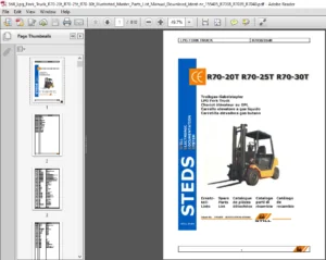
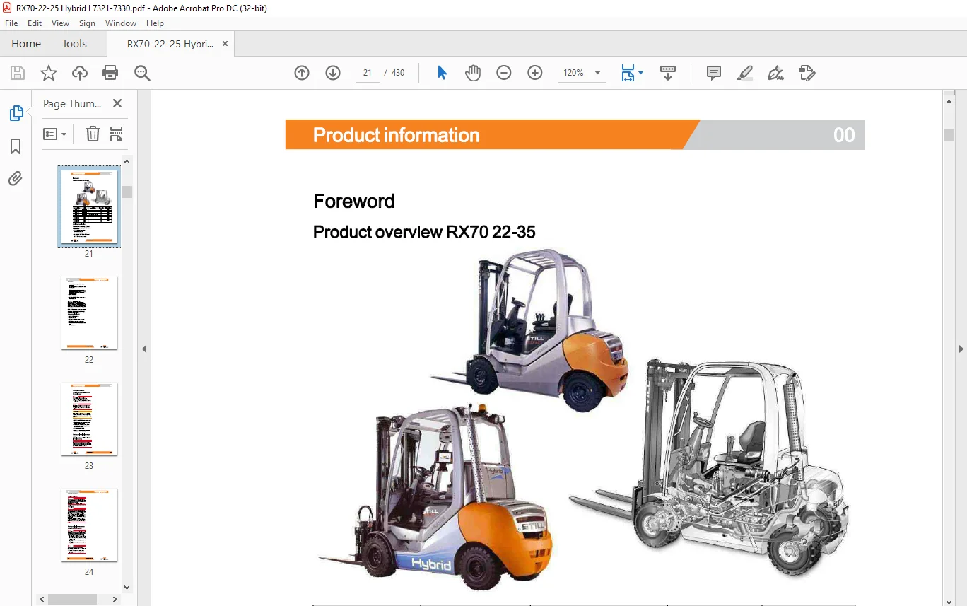
Product overview RX70 22-35
- Ergonomic driver?s workplace Generation 2 mini-lever Generation 2 display operating unit
- Diesel-electric drive with three-phase AC technology Closed-loop AC drive technology
- Intelligent drive management for very low consumption Hydraulic fans and exhaust system with new air cooling duct Blue-Q Characteristic curve optimisation of the drive The following can be parameterised: switching off auxiliary consumers and enabling the consumption display
- Load measurement
- Lift mast vertical position
- Hydraulics blocking function in accordance with EN ISO 3691-1
IMAGES PREVIEW OF THE MANUAL:
TABLE OF CONTENTS:
Still STED Diesel LPG forklift trucks RX70-22 RX70-25 RX70-30 RX70-35 Workshop Manual 171866 – PDF DOWNLOAD
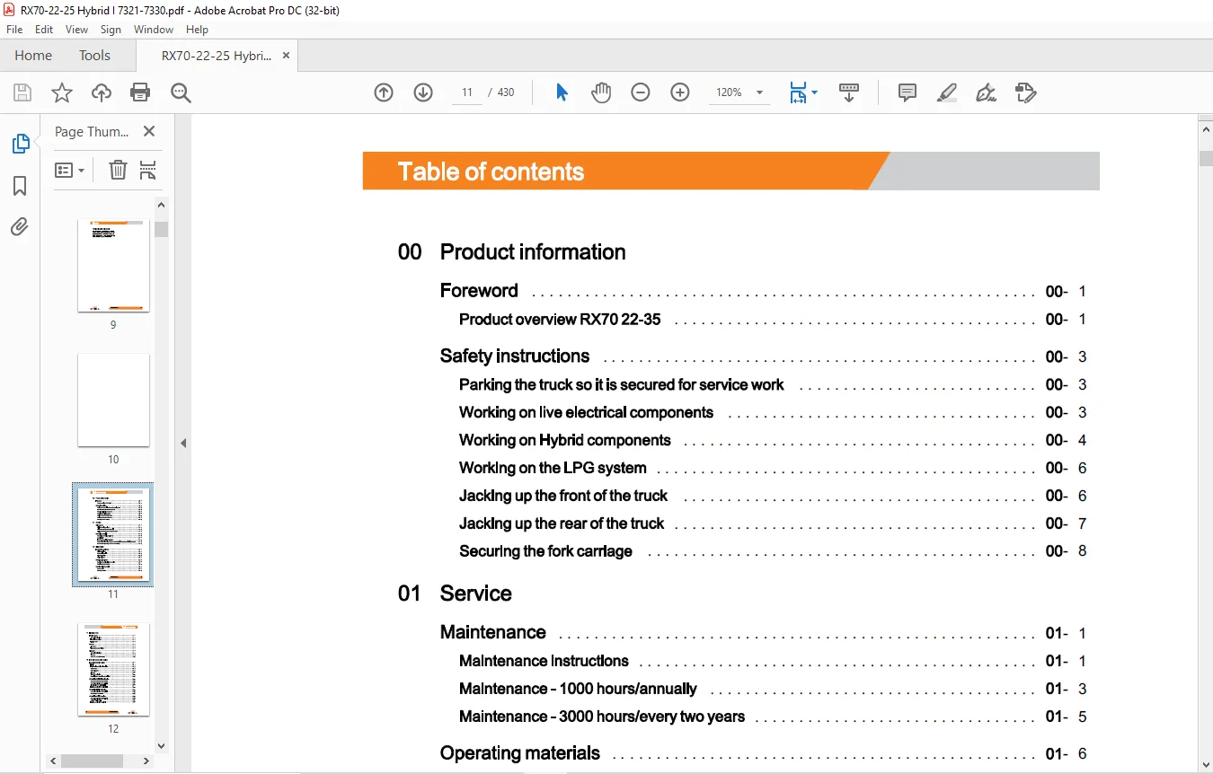
00 Product information
Foreword 00
Product overview RX70 22-35 00
Safety instructions 00
Parking the truck so it is secured for service work 00
Working on live electrical components 00
Working on Hybrid components 00
Working on the LPG system 00
Jacking up the front of the truck 00
Jacking up the rear of the truck 00
Securing the fork carriage 00
01 Service
Maintenance 01
Maintenance instructions 01
Maintenance – 1000 hours/annually 01
Maintenance – 3000 hours/every two years 01
Operating materials 01
Measuring and testing equipment 01
Special tool 01
Harnesses and hoists, 1.0 t – 3.5 t 01
Standardised tightening torques for standard-pitch threads and fine-pitch threads 01
Standardised tightening torques for hose fittings 01
02 Diagnostics
Introduction to DiaMon 02
STEDS-Navigator 02
CAN box diagnostics 02
Diagnostic set-up 02
Starting DiaMon 02
Working with DiaMon 02
Reading out and clearing the error list 02
Reading out access codes 02
Working using the ABE 02
Read error list 02
Clearing error lists 02
X 171866 EN – 08/2016
Table of contents
11 Electric motor
Traction motor 11
General technical data 11
Electrical connections 11
Traction motor 11
Sensors 11
Pin sensor 11
Temperature sensor KTY84 11
Alternator 11
General technical data 11
Alternator 11
Alternator removal-installation 11
12 Internal combustion engine
Internal combustion engine 12
Engine 12
Engine unit Removal and installation 12
Starter motor 12
Starter ring gear 12
Alternator 12
Alternator monitoring 12
Retrofitting the 110-A alternator for TCU 1 12
VW 1.9-litre SDI/TDI diesel engine 12
General technical data VW 1.91 SDI 12
General technical data VW 1.91 TDI 12
Diesel engine VW 1.91 SDI/TDI 12
Engine control unit VW 1.91 SDI/TDI 12
VW 2.0-litre TDI diesel engine 12
General technical data VW 2.01 TDI 12
Diesel engine VW 2.01 TDI 12
VW 2.0-litre SPI LPG engine 12
General technical data VW 2.01 SPI 12
VW LPG – 2.0 litre BEF 12
Engine control unit VW 2.01 SPI 12
171866 EN – 08/2016 XI
Table of contents
13 Combustion engine – attachments
Air intake/ filter 13
Air intake 13
Air filter 13
Cooling system 13
Cooling circuit 13
Water pump 13
Coolant 13
Checking, topping up and changing the coolant 13
Radiator system 13
Radiator Removal and installation 13
Fan wheel rotor- fan motor 13
Diesel fuel system 13
Fuel system 13
Fuel filter 13
Low fuel warning threshold 13
LPG system 13
LPG system 13
lmpco components 13
Evaporator function – gas mixer 13
Suction module 13
MAP/MAT sensor 0B6 13
Chassis module 13
Actuator unit 13
Gas shut-off valve unit 13
Gas shut-off valve monitoring 13
Shut-down due to lack of gas 13
Maintenance and test specifications 13
Testing for leaks in the LPG system 13
Testing CO level in exhaust gases 13
Servicing the LPG filter 13
Servicing the 30-bar high-pressure relief valve 13
Evaporator – maintenance 13
Safety valve – 1. 7 bar 13
LPG cylinder/tank 13
LPG cylinder 13
XII 171866 EN – 08/2016
Table of contents
14 Combustion engine – exhaust system
Exhaust system – diesel 14
Exhaust system 14
Exhaust system – particle filter 14
General technical data – Eberspacher 14
Structure of the Eberspacher particle filter 14
7.5 kW Eberspacher particle filter 14
Regeneration 14
Maintenance instructions 14
Exhaust system – LPG 14
Exhaust system 14
Lambda control system 14
Lambda sensor 14
Three-way catalytic converter 14
22 Mechanical drive axle
Drive axle 8.30 22
General technical data, Carraro 8.30 22
Drive axle 22
Wheel drive 22
Checking the oil level, changing the oil 22
Removal and installation of the drive axle 22
Traction motor 22
Service brake 22
Differential gearbox 22
30 Chassis, bodywork and fittings
Chassis 30
Floorplate 30
Working with gas springs 30
Counterweight 30
Counterweight 30
34 Driver’s compartment
Hood – covering – insulation 34
Motor hood 34
171866 EN – 08/2016 XIII
Table of contents
42 Steering system
Hydraulic steering 42
General technical data 42
Steering system 42
Steering – error detection 42
Steering unit 42
Priority valve 42
Steering wheel and steering column 42
Steering column 42
Steering axle 42
General technical data 42
Swing axle 42
Swing axle Removal and installation 42
Wheel hub 42
Steering angle 42
Tie rod 42
Axle stub 42
50 Operating devices
Drive and brake actuation 50
Brake actuator 50
Replacing the brake cable 50
Actuating force of the handbrake 50
Parking brake switch 1 S3 50
Brake sensor 1 B2 50
Accelerator- single-pedal 50
Dual pedal 50
Accelerator- dual pedal 50
Operating devices 50
Hand lever 50
Joystick 50
Joystick operation 50
Generation 2 mini-lever 50
Generation 2 mini-leverActuation 50
Tip switch 50
Generation 1 mini-lever 50
Axle assignment 50
XIV 171866 EN – 08/2016
Table of contents
Joystick 4Plus 50
Axle assignment – Joystick 4Plus 50
56 Display elements
Operating console 56
Direction indicator module (Fabli) 56
Display 56
Display and operating unit, generation 2 (ABE 2) 56
ABE 2 Installation and removal 56
Display operating unit (ABE 1) Generation 1 56
ABE 1 Installation and removal 56
Drive direction turn indicator display 56
60 Electrics/Electronics
General 60
General technical data 60
Overview of the controllers 60
Overview of electrical components 60
Software compatibility 60
PAN process 60
Parameter management 60
Error ring buffer 60
Intermediate circuit 60
Insulation measurement 60
Hybrid component insulation measurements 60
Traction motor temperature monitoring 60
Temperature monitoring, traction inverter with air cooling 60
Availability of drive mode and driving behaviour 60
Driving mode – driving behaviour Description 60
Blue-Q=IQ 60
Wiring 60
CAN bus system 60
CAN bus connections 60
Power cables 60
Maintenance guidelines for power cables 60
Repair – Contact elements 60
Electrical system 60
Fusebox 60
171866 EN – 08/2016 XV
Table of contents
Fuses 60
Relays in the fuse box 60
Sensor system 60
Vertical lift mast position 60
Tilt angle sensor 7B46 60
Tilt angle sensor parameters 60
Installation of the vertical lift mast position 60
Load measurement 60
Load measurement pressure sensor 60
Additional electrical installation 60
Option Board 60
CAN-Power-Port (CPP) 60
CPP 1/CPP 3 60
CPP2/CPP4 60
CPP2B 60
Soot CPP (CPP5) 60
Relay-Power-Port 60
64 Electronic controllers
Truck control unit 64
Truck Control Unit (TCU) 64
TCU, generation 2 (TCU 2) 64
Truck Control! Unit (TCU) Removal and installation 64
Converters 64
Inverter 64
Hybrid I converter 64
ConvertersRemoval and installation 64
Brake resistor 64
Hybrid components 64
Hybrid I function 64
DC/DC converter 64
DC/DC converter Removal and installation 64
Storage module – energy accumulators 64
Storage module Removal and installation 64
Forced ventilation 64
XVI 171866 EN – 08/2016
Table of contents
69 Batteries and accessories
Starter battery 69
Starter battery 69
70 Hydraulics
General 70
General technical data 70
Depressurising the hydraulics 70
Lifting operating speeds 70
Tilting operating speeds 70
Lowering operating speeds 70
Safety check 70
Forward tilt safety test 70
Lowering safety test 70
Safety checks of hose assembly 70
Basic hydraulics 70
Basic hydraulics 70
Fan motor control unit 70
Fan control valve 70
Steering hydraulics 70
Operating hydraulics 70
Variable displacement pump 70
Hybrid variable displacement pump 70
Pump regulator 70
Variable pumpRemoval and installation 70
Hydraulic tank 70
Hydraulic oil 70
Return filter 70
Breather 70
Suction filter 70
High-pressure filter 70
Conical nipple fittings (CNF) 70
Bolted joint 70
71 Operating hydraulics
Tilt cylinder 71
Mast tilt 71
Tilt cylinder Removal and installation 71
171866 EN – 08/2016 XVII
Table of contents
Changing the set of seals2200-5000 kg – LSP 500 71
Additional hydraulics 71
Attachments 71
Second operating function for attachments 71
Clamp locking mechanism for hand levers 71
Accumulator 71
Accumulator 71
Checking the accumulator 71
76 Valves
Hand lever 76
General technical data 76
Hand lever valve block 76
Valve block Removal / installation 76
Directional control valve block 76
Check valve for hydraulics blocking function 76
Hydraulic transmitter 76
Servo hydraulics 76
General technical data 76
Servo hydraulics valve block 76
Directional control valve block 76
Directional control valve function Lifting 76
Directional control valve function Lowering 76
80 Load lift system
Mast bearings 80
Carraro 8.30 mast bearing 80
81 Lift mast
Lift mast 81
General technical data 81
Hose safety valve of triplex mast 81
Support roller play ( 108/117 /130) 81
Load chains – Checking and cleaning 81
Run-out barrier 81
Working on lift masts 81
Lift mast- removal 81
Lift mast – installation 81
Telescopic lift mast
Telescopic lift mast (108/117/130)
Adjusting the load chains Telescopic lift mast (108/117/130)
Ni Ho lift mast
NiHo lift mast (108/117/130)
Adjusting the load chains NiHo lift mast (108/117/130)
Triplex lift mast
Triple lift mast (108/117/130)
Removing the support rollers in the lift mast
Assembling the lift mast after replacing the support rollers
Outer load chains and chain rollers
Middle load chain and chain roller
Adjusting the outer load chains Triple lift mast ( 108/117 /130)
Adjusting the middle load chain Triple lift mast (108/117/130)
Lift cylinders
Lift jack
Working on lift cylinders
Outer cylinder
Disassembling/assembling the outer cylinder
Centre cylinder
Disassembling/assembling the middle cylinder
End position damping, type B (bottom)
End position damping, type A (top)
84 Load support
Fork carriage
Fork carriage
Annex
X Circuit diagrams
Hydraulics
Hand lever until 12/2009
Hand lever from 01/2010
Servo hydraulic
Questions? Email us: [email protected]
https://vimeo.com/857101069?share=copy
PLEASE NOTE:
- This is the SAME MANUAL used by the dealerships to diagnose your vehicle
- No waiting for couriers / posts as this is a PDF manual and you can download it within 2 minutes time once you make the payment.
- Your payment is all safe and the delivery of the manual is INSTANT – You will be taken to the DOWNLOAD PAGE.
- So have no hesitations whatsoever and write to us about any queries you may have : heydownloadss @gmail.com
S.M