Trusted Business
Verified & Licensed
Virus Free Files
100% Safe Downloads
Secure Payment
SSL Protected
Instant Delivery
Available Immediately
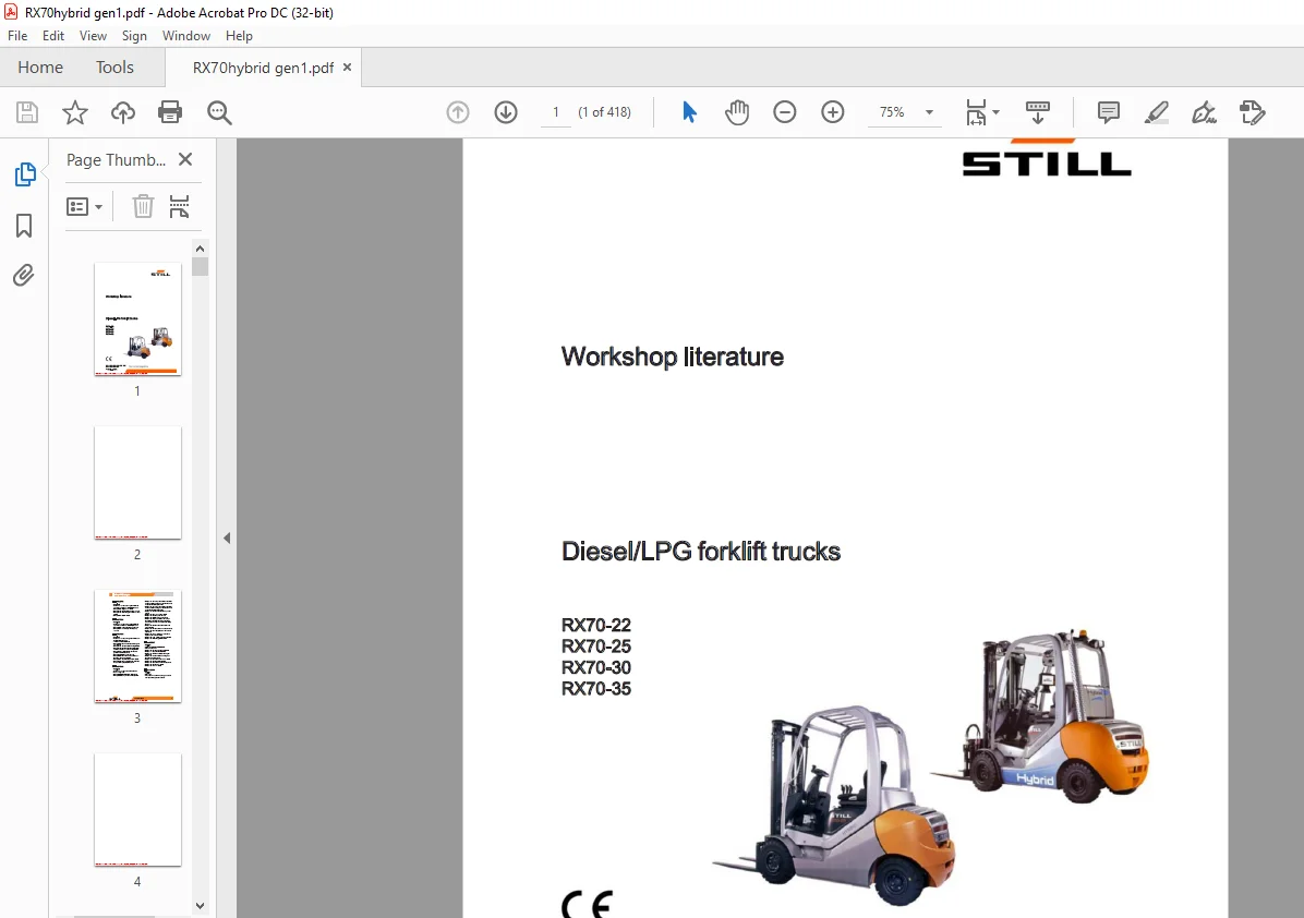
STILL STED Diesel LPG forklift trucks RX70-22 RX70-25 RX70-30 RX70-35 Workshop Manual – PDF DOWNLOAD
$27.95
STILL STED Diesel LPG forklift trucks RX70-22 RX70-25 RX70-30 RX70-35 Workshop Manual – PDF DOWNLOAD
Instant PDF Download
Available immediately
Save to Your Device
Download & keep forever
Antivirus Scanned
100% virus-free
Trusted Worldwide
175,000+ customers
Description
STILL STED Diesel LPG forklift trucks RX70-22 RX70-25 RX70-30 RX70-35 Workshop Manual – PDF DOWNLOAD
FILE DETAILS:
STILL STED Diesel LPG forklift trucks RX70-22 RX70-25 RX70-30 RX70-35 Workshop Manual – PDF DOWNLOAD
Language : English
Pages : 418
Downloadable : Yes
File Type : PDF
DESCRIPTION:
STILL STED Diesel LPG forklift trucks RX70-22 RX70-25 RX70-30 RX70-35 Workshop Manual – PDF DOWNLOAD
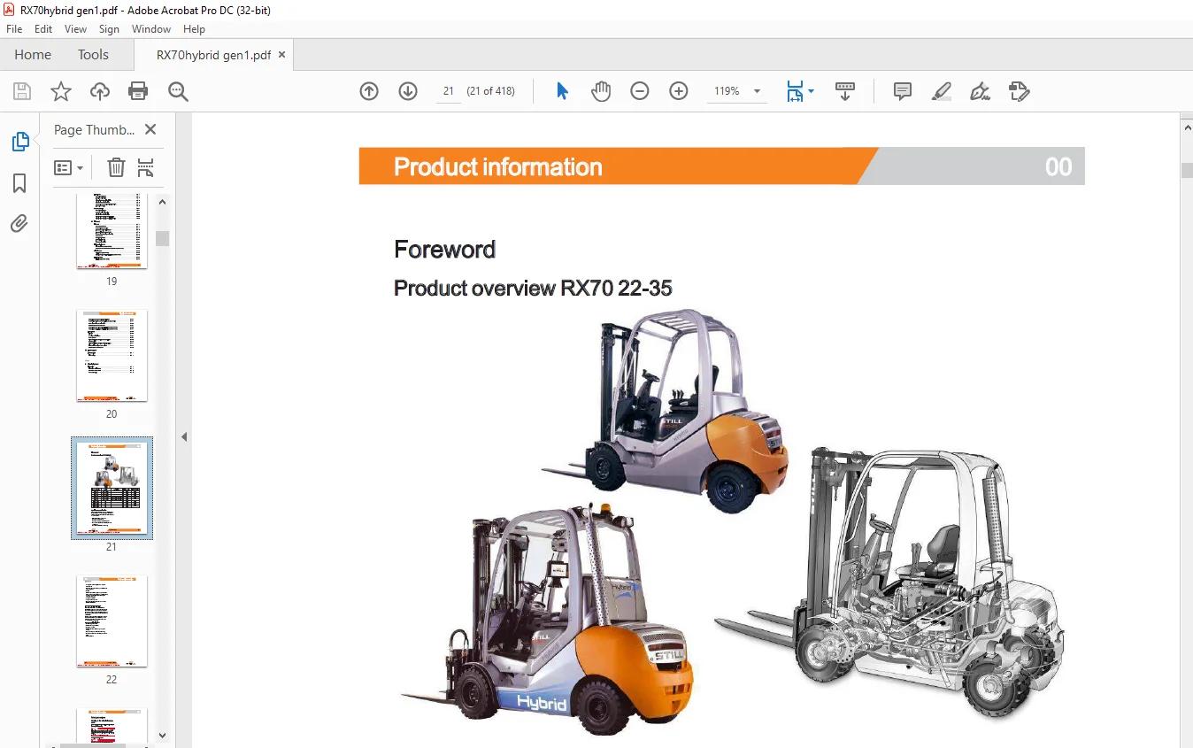
Special features of this series
The series described belongs to the RX family. A small number units with a high proportion of common parts make up many different trucks of various versions.
• Ergonomic driver’s workplace .
Generation 2 mini-lever Generation 2 display operating unit
Diesel-electric drive with three-phase AC technology Closed-loop AC drive technology
Foreword
Intelligent drive management for very low consumption Hydraulic fans and exhaust system with new air cooling duct
• Blue-Q Characteristic curve optimisation of the drive The following can be parameterised: switching off auxiliary consumers and enabling the consumption display
• Load measurement .
• Lift mast vertical position
• Hydraulics blocking function in accordance with EN ISO 3691-1
IMAGES PREVIEW OF THE MANUAL:
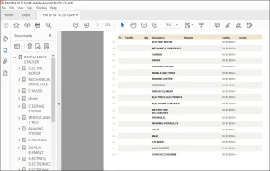
TABLE OF CONTENTS:
STILL STED Diesel LPG forklift trucks RX70-22 RX70-25 RX70-30 RX70-35 Workshop Manual – PDF DOWNLOAD
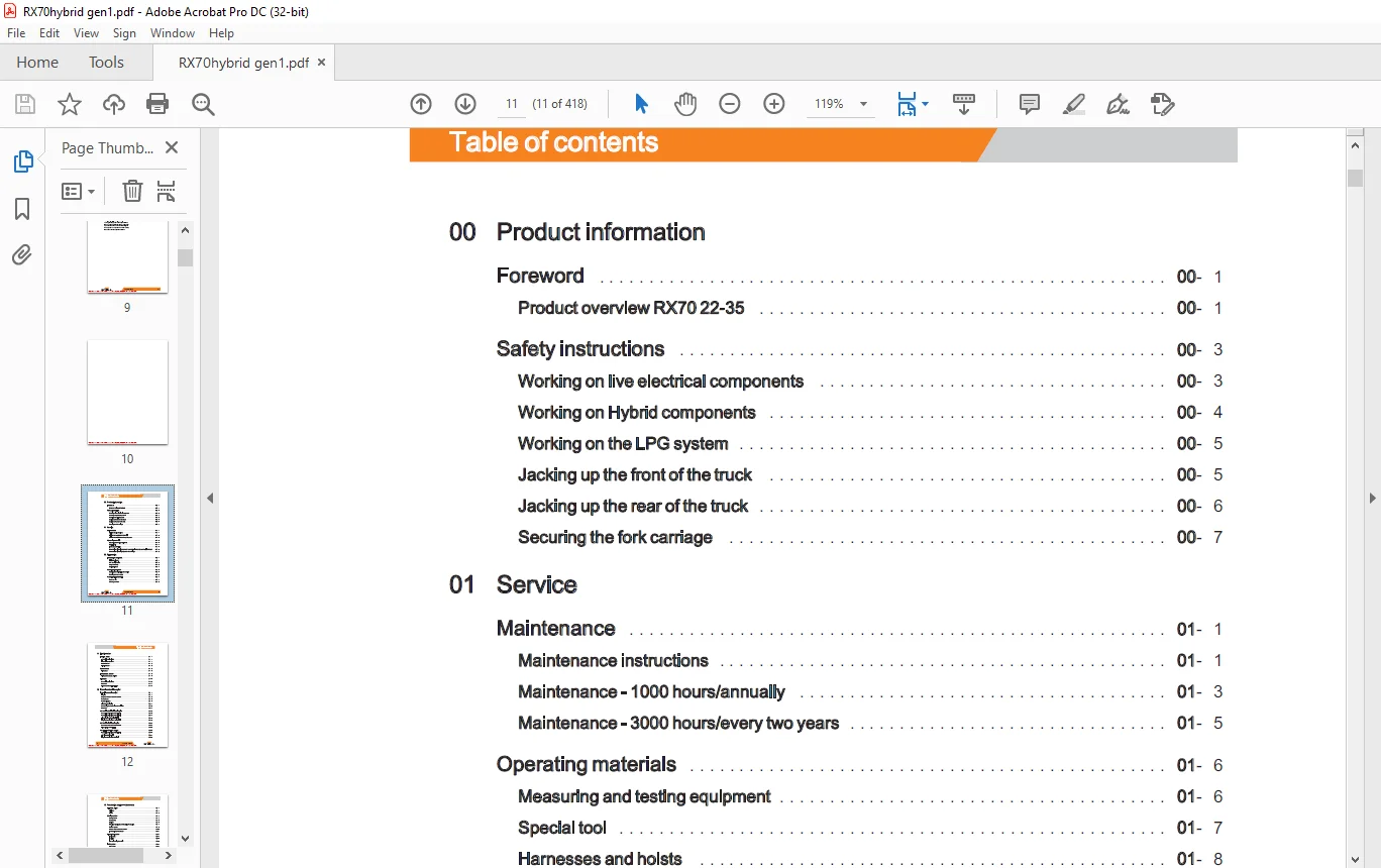
Table of contents
00 Product information
Foreword 00- 1
Productoverview RX7022-35 00- 1
Safetyinstructions 00- 3
Working on live electricalcomponents LL 00- 3
WorkingonHybridcomponents 00- 4
Workingonthe LPGsystem 00- 5
Jackingupthe frontofthetruck iL 00- 5
Jacking up therearofthetruck iL 00- 6
Securing theforkcarriage 00- 7
01 Service
Maintenance 01- 1
Maintenanceinstructions 01-1
Maintenance-1000 hours/annually 01- 3
Maintenance – 3000 hours/everytwoyears 01- 5
Operatingmaterials 01- 6
Measuring and testingequipment 01- 6
Specialtool 0-7
Harnessesandhoists LL 01- 8
Standardised tightening torques for standard-pitch threads and fine-pitch threads 01- 9
Standardised tightening torques for hose fittings 01- 9
02 Diagnostics
IntroductiontoDiaMon 02- 1
STEDS-Navigator 02- 1
CANboxdiagnostics 02- 2
Diagnosticset-up 02- 3
Starting DiaMon 02- 4
STEDS-Navigator 02- 1
CANboxdiagnostics 02- 2
Diagnosticset-up 02- 3
Starting DiaMon 02- 4
WorkingwithDiaMon 02- 5
Reading outandclearingtheerrorlist 02- 5
Readingoutaccesscodes 02- 6
Reading outandclearingtheerrorlist 02- 5
Readingoutaccesscodes 02- 6
Workingusingthe ABE 02-7
Readerrorlist 02- 7
Clearingerrorlists 02- 9
Readerrorlist 02- 7
Clearingerrorlists 02- 9
Tractionmotor 11-1
Generaltechnicaldata 11-1
Electricalconnections 11-1
Traction motor 1- 2
Tractionmotor 11-3
Generaltechnicaldata 11-1
Electricalconnections 11-1
Traction motor 1- 2
Tractionmotor 11-3
Speed sensor 11- 6
Pin Sensor 11- 6
Pin Sensor 11- 6
Temperature SEeNSOr ii 11- 8
Temperature sensor KTY84 11- 8
Temperature sensor KTY84 11- 8
Alternator 11-10
Generaltechnicaldata 11-10
Alternator 11-11
Alternator removal-installation 11-12
Generaltechnicaldata 11-10
Alternator 11-11
Alternator removal-installation 11-12
12 Internal combustion engine
Internal combustionengine 12-1
Engine 12- 1
Engine unitRemoval and installation 12- 3
Startermotor 12- 8
Starterringgear 12- 9
Alternatormonitoring 12-11
Retrofitting the 110-A alternatorfor TCU1 12-13
Alternator 12-14
Engine 12- 1
Engine unitRemoval and installation 12- 3
Startermotor 12- 8
Starterringgear 12- 9
Alternatormonitoring 12-11
Retrofitting the 110-A alternatorfor TCU1 12-13
Alternator 12-14
VW 1 9-litre SDI/TDI dieselengine 12-16
General technicaldataVW 1 91SDI 12-16
General technicaldata VW 1 91TDI 12-17
Dieselengine VW 1 QISDI/TDI 12-18
Engine control unit VW 1 9ISDI/TDI 12-19
General technicaldataVW 1 91SDI 12-16
General technicaldata VW 1 91TDI 12-17
Dieselengine VW 1 QISDI/TDI 12-18
Engine control unit VW 1 9ISDI/TDI 12-19
VW 2 0-litre TDI dieselengine 12-22
General technical data VW 2 01 TDI 12-22
Dieselengine VW 2 01 TDI 12-23
General technical data VW 2 01 TDI 12-22
Dieselengine VW 2 01 TDI 12-23
VW 2 0-litre SPILPGengine 12-25
General technicaldata VW 2 01SPI 12-25
VWLPG-20Iitre BEF 12-27
Engine controlunitVW 2 01SPI 12-28
General technicaldata VW 2 01SPI 12-25
VWLPG-20Iitre BEF 12-27
Engine controlunitVW 2 01SPI 12-28
13 Combustion engine — attachments
Airintake /filter 13- 1
Airintake LLL 13- 1
Airfilter 13- 2
Airintake LLL 13- 1
Airfilter 13- 2
Coolingsystem 13- 4
Coolingcircuit 13- 4
Waterpump 13- 5
Coolant 13- 6
Checking, topping up and changingthecoolant 13- 7
Radiatorsystem 13- 9
Radiator Removal and installation 13-10
Fanwheelrotor-fanmotor 13-11
Coolingcircuit 13- 4
Waterpump 13- 5
Coolant 13- 6
Checking, topping up and changingthecoolant 13- 7
Radiatorsystem 13- 9
Radiator Removal and installation 13-10
Fanwheelrotor-fanmotor 13-11
Diesel fuel system 13-14
Fuelsystem 13-14
Fuelfilter 13-15
Low fuelwarningthreshold 13-15
Fuelsystem 13-14
Fuelfilter 13-15
Low fuelwarningthreshold 13-15
LPG system 13-17
LPG system 13-17
IMPCOCOMPONENtS 13-18
Evaporator function-gasmixer 13-19
Suctionmodule 13-21
MAP/MAT sensor0B6 13-23
Chassismodule 13-23
Actuatorunit 13-25
Gasshut-offvalveunit 13-26
Gas shut-offvalve monitoring 13-26
Shut-downduetolackofgas i 13-27
Maintenance and test specifications iL 13-28
Testing forleaksinthe LPGsystem 13-29
Testing CO levelinexhaustgases 13-30
Servicingthe LPGfilter 13-32
Servicing the 30-bar high-pressure reliefvalve 13-33
Evaporator-maintenance LL 13-34
Safetyvalve-1 7bar 13-37
LPGecylinderftank 13-3
14 Combustion engine — exhaust system
Exhaustsystem-diesel iL 14- 1
Exhaustsystem 14- 1
Exhaust system – particlefilter 14- 2
General technical data-Eberspacher 14- 2
Structure of the Eberspécher particlefilter 14- 3
7 5 kW Eberspacher particlefilter 14- 3
Regeneration LL 14- 6
Maintenance instructions 14- 8
Exhaustsystem —LPG 14- 9
Lambdacontrolsystem 14- 9
Lambdasensor 14-10
Three-way catalyticconverter LL 14-12
22 Mechanical drive axle
Driveaxle 8 30 22-1
General technical data, Carraro 8 30 i 22- 1
Drive axle 22- 3
Wheeldrive 22- 4
Removal and installation of thedriveaxle 22- 6
Servicebrake 22-9
Differential gearbox 22-12
General technical data, Carraro 8 30 i 22- 1
Drive axle 22- 3
Wheeldrive 22- 4
Removal and installation of thedriveaxle 22- 6
Servicebrake 22-9
Differential gearbox 22-12
31 Chassis
Chassis 31-1
Floorplate 31-1
Counterweight 31- 2
Counterweight 31- 2
Floorplate 31-1
Counterweight 31- 2
Counterweight 31- 2
34 Driver’s compartment
Hood —covering—insulation 34- 1
Motorhood 34- 1
Motorhood 34- 1
42 Steering system
Hydraulicsteering iL 42-1
Generaltechnicaldata 42-1
Steering system 42- 2
Steering—errordetection LL 42- 3
Generaltechnicaldata 42-1
Steering system 42- 2
Steering—errordetection LL 42- 3
Steeringunit 42- 3
Priority valve 42- 6
Steering wheel and steeringcolumn 42- 7
Steering column LLL 42- 7
Steeringaxle 42-11
Generaltechnicaldata 42-11
Swing axle 42-12
Swing axle Removal and installation 42-13
Wheelhub 42-15
Steeringangle LL 42-17
Tierod 42-18
Axlestub 42-19
Priority valve 42- 6
Steering wheel and steeringcolumn 42- 7
Steering column LLL 42- 7
Steeringaxle 42-11
Generaltechnicaldata 42-11
Swing axle 42-12
Swing axle Removal and installation 42-13
Wheelhub 42-15
Steeringangle LL 42-17
Tierod 42-18
Axlestub 42-19
49 Brake system
Hydraulicservicebrake 49- 1
Brakesensor1B2 LLL 49- 1
Parkingbrake 49- 2
Replacingthebrakecable 49- 2
Actuating force ofthe handbrake 49- 2
Parkingbrake switch 183 49- 3
Brakesensor1B2 LLL 49- 1
Parkingbrake 49- 2
Replacingthebrakecable 49- 2
Actuating force ofthe handbrake 49- 2
Parkingbrake switch 183 49- 3
50 Operating devices
Singlepedal 50- 1
Accelerator—single-pedal 50- 1
Dualpedal 50- 4
Accelerator—dualpedal 50- 4
Operatingdevices 50- 7
Handlever 50- 7
Joystick oo 50- 8
Joystickoperation LLL 50-10
Generation2mini-lever LL 50-12
Generation 2mini-leverActuation 50-14
Tipswitch Lo 50-16
Generation Tmini-lever 50-18
Axleassignment LLL 50-19
Joystick4Plus 50-23
Axle assignment -Joystick4Plus 50-24
56 Display elements
Operatingconsole
Direction indicatormodule (Fabli)
Direction indicatormodule (Fabli)
Display
Display and operating unit, generation2(ABE2)
ABE 2 Installationandremoval
Display operating unit (ABE 1) Generation1
ABE 1 Installationand removal
Display and operating unit, generation2(ABE2)
ABE 2 Installationandremoval
Display operating unit (ABE 1) Generation1
ABE 1 Installationand removal
Drive direction tum indicatordisplay
60 Electrics/Electronics
General
Generaltechnicaldata
Overviewofthecontrollers
Overview of electricalcomponents
Software compatibility
PANDProcess
Parametermanagement
Errorringbuffer
Intermediatecircuit
Insulation measurement LL
Hybrid component insulation measurements
Traction motor temperature monitoring
Temperature monitoring, traction inverter with aircooling
Drive mode — driving behaviour Availability
Driving mode — driving behaviour Description
Blue-Q=1Q
Wiring
CANbussystem i
CANbusconnections
Powercables
Maintenance guidelines forpowercables
CANbussystem i
CANbusconnections
Powercables
Maintenance guidelines forpowercables
Repair-Contactelements
Electrical system L
Fusebox
Fusebox
Sensorsystem 60-30
Vertical lift mast position 60-30
Titanglesensor7B46 LL 60-31
Tiltangle sensorparameters 60-33
Installation of the vertical lift mast position 60-34
Load measurement LL 60-37
Load measurement pressure SENSOr o oo 60-39
Vertical lift mast position 60-30
Titanglesensor7B46 LL 60-31
Tiltangle sensorparameters 60-33
Installation of the vertical lift mast position 60-34
Load measurement LL 60-37
Load measurement pressure SENSOr o oo 60-39
Additional electrical installation 60-40
OptionBoard 60-40
CAN-Power-Port (CPP) 60-42
CPP CPP 3 60-42
CPP 2/CPP 4 60-43
CPP 2B 60-45
Soot CPP (CPPS) 60-46
Relay-Power-Port 60-46
OptionBoard 60-40
CAN-Power-Port (CPP) 60-42
CPP CPP 3 60-42
CPP 2/CPP 4 60-43
CPP 2B 60-45
Soot CPP (CPPS) 60-46
Relay-Power-Port 60-46
64 Electronic controllers
Truckcontrolunit LL 64- 1
Truck Control Unit (TCU) 64- 1
TCU, generation2(TCU2) i 64- 2
Truck Controll Unit (TCU) Removal and installation 64- 2
Truck Control Unit (TCU) 64- 1
TCU, generation2(TCU2) i 64- 2
Truck Controll Unit (TCU) Removal and installation 64- 2
Converters 64- 5
Inverter 64- 5
Hybrid converter 64- 6
ConvertersRemoval andinstallation 64- 8
Brakeresistor LL 64-11
Inverter 64- 5
Hybrid converter 64- 6
ConvertersRemoval andinstallation 64- 8
Brakeresistor LL 64-11
Hybridcomponents 64-13
Hybrid function 64-13
DC/DC converter 64-14
DC/DC converter Removal and installation 64-15
Storage module —energy accumulators 64-18
Storage module Removal andinstallation 64-20
Forced ventilation 64-21
Hybrid function 64-13
DC/DC converter 64-14
DC/DC converter Removal and installation 64-15
Storage module —energy accumulators 64-18
Storage module Removal andinstallation 64-20
Forced ventilation 64-21
69 Batteries and accessories
Starterbattery 69- 1
Starterbattery 69- 1
Generaltechnicaldata 70- 1
Depressurisingthe hydraulics 70- 3
Liftingoperatingspeeds 70- 3
Tilting operatingspeeds LL 70- 4
Lowering operatingspeeds LL 70- 5
Starterbattery 69- 1
Generaltechnicaldata 70- 1
Depressurisingthe hydraulics 70- 3
Liftingoperatingspeeds 70- 3
Tilting operatingspeeds LL 70- 4
Lowering operatingspeeds LL 70- 5
Safetycheck 70- 6
Forwardftiltsafetytest 70- 6
Lowering safetytest LL 70- 6
Safety checksofhoseassembly lL 70- 7
Forwardftiltsafetytest 70- 6
Lowering safetytest LL 70- 6
Safety checksofhoseassembly lL 70- 7
Basichydraulics 70- 8
Basichydraulics 70- 8
Fanmotorcontrolunit 70-10
Fancontrolvalve 70-11
Steering hydraulics 70-13
Operatinghydraulics 70-14
Variable displacementpump 70-16
Hybrid variable displacementpump 70-18
Pumpregulator 70-19
Variable pumpRemoval and installation 70-20
Hydraulictank 70-22
Hydraulicoil 70-23
Returnfilter 70-24
Breather 70-25
Suction filter 70-26
High-pressurefilter 70-27
Conical nipple fittings (CNF) 70-28
Bolted joint 70-28
71 Operating hydraulics
Tilteylinder 71-1
Masttilt 71-1
Tilt cylinder Removal and installation 71- 2
Changing the set of seals2200-5000kg-LSP 500 71- 3
Masttilt 71-1
Tilt cylinder Removal and installation 71- 2
Changing the set of seals2200-5000kg-LSP 500 71- 3
Additional hydraulics 71- 6
Attachments 71- 6
Attachments 71- 6
Second operating function forattachments 71- 8
Clamp locking mechanism forhandlevers 71- 8
76 Valves
Hand lever 76- 1
Generaltechnicaldata 76- 1
Hand levervalveblock 76- 2
Valve block Removal /installation 76- 3
Directional control valve block 76- 5
Check valve for hydraulics blocking function 76- 7
Hydraulictransmitter 76- 9
Servohydraulics 76-11
Generaltechnicaldata 76-11
Servo hydraulics valveblock 76-12
Directional control valve block 76-13
Directional control valve function Lifting 76-16
Directional control valve function Lowering 76-18
81 Lift mast
Liftmast 81- 1
Generaltechnicaldata 81- 1
Carraro 8 30 mastbearing 81-1
Hose safety valve of triplexmast 81- 3
Supportroller play (108/117/130) 81- 6
Load chains – Checkingandcleaning 81- 7
Run-outbarrier 81- 8
Workingonliftmasts 81-10
Lift mast—removal 81-11
Lift mast—installation 81-12
Generaltechnicaldata 81- 1
Carraro 8 30 mastbearing 81-1
Hose safety valve of triplexmast 81- 3
Supportroller play (108/117/130) 81- 6
Load chains – Checkingandcleaning 81- 7
Run-outbarrier 81- 8
Workingonliftmasts 81-10
Lift mast—removal 81-11
Lift mast—installation 81-12
Telescopicliftmast 81-15
Telescopic lift mast (108/117/130) i 81-15
Adjusting the load chains Telescopic lift mast (108/117/130) 81-16
Telescopic lift mast (108/117/130) i 81-15
Adjusting the load chains Telescopic lift mast (108/117/130) 81-16
NiHoliftmast 81-18
NiHoliftmast (108/117/130) 81-18
Adjusting the load chains NiHo lift mast (108/117/130) 81-20
NiHoliftmast (108/117/130) 81-18
Adjusting the load chains NiHo lift mast (108/117/130) 81-20
Triplex liftmast 81-22
Triple lift mast (108/117/130) 81-22
Triple lift mast (108/117/130) 81-22
Removing the support rollersintheliftmast
Assembling the lift mast after replacing the supportrollers
Outer load chains and chainrollers
Middle load chainand chainroller
Adjusting the outer load chains Triple lift mast (108/117/130)
Adjusting the middle load chain Triple lift mast (108/117/130)
Assembling the lift mast after replacing the supportrollers
Outer load chains and chainrollers
Middle load chainand chainroller
Adjusting the outer load chains Triple lift mast (108/117/130)
Adjusting the middle load chain Triple lift mast (108/117/130)
Lifteylinders
Liftjack
Working onliftcylinders
Outercylinder
Disassembling/assembling the outercylinder
Centrecylinder
Disassembling/assembling the middle cylinder
End position damping ofoutercylinder
Liftjack
Working onliftcylinders
Outercylinder
Disassembling/assembling the outercylinder
Centrecylinder
Disassembling/assembling the middle cylinder
End position damping ofoutercylinder
Middle cylinderenddampener
84 Load support
Forkcarriage
Forkcarriage
Forkcarriage
Annex
X Circuit diagrams
Hydraulics i
Hand leveruntil 12/2009
Hand lever from 01/2010
Hand leveruntil 12/2009
Hand lever from 01/2010
Need help? Contact: [email protected]
https://vimeo.com/854574787?share=copy
PLEASE NOTE:
- This is the same manual used by the DEALERSHIPS to SERVICE your vehicle.
- The manual can be all yours – Once payment is complete, you will be taken to the download page from where you can download the manual. All in 2-5 minutes time!!
- Need any other service / repair / parts manual, please feel free to contact us at heydownloadss @gmail.com . We may surprise you with a nice offer
S.M