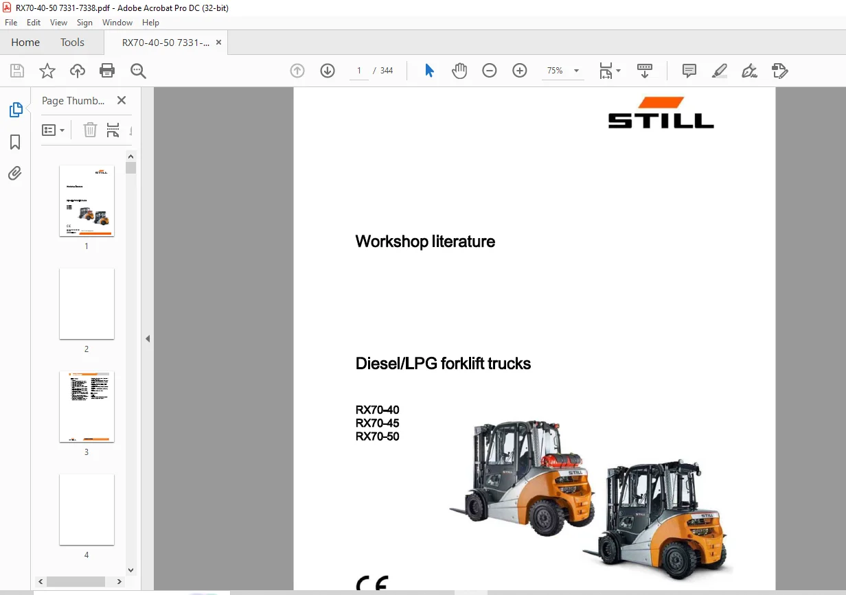
STILL STED Diesel LPG forklift trucks RX70-40 RX70-45 RX70-50 workshop Manual – PDF DOWNLOAD
$28.95
STILL STED Diesel LPG forklift trucks RX70-40 RX70-45 RX70-50 workshop Manual – PDF DOWNLOAD
Description
STILL STED Diesel LPG forklift trucks RX70-40 RX70-45 RX70-50 workshop Manual – PDF DOWNLOAD
FILE DETAILS:
STILL STED Diesel LPG forklift trucks RX70-40 RX70-45 RX70-50 workshop Manual – PDF DOWNLOAD
Language : English
Pages : 344
Downloadable : Yes
File Type : PDF
IMAGES PREVIEW OF THE MANUAL:
DESCRIPTION:
STILL STED Diesel LPG forklift trucks RX70-40 RX70-45 RX70-50 workshop Manual – PDF DOWNLOAD
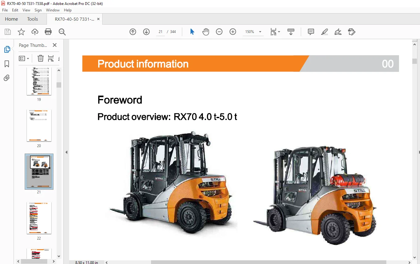
Foreword
Product overview: RX70 4.0 t-5.0 t
Parking the truck so it is secured
for service work
? Lower the unladen fork carriage to the ground.
? Tilt the lift mast forwards until the tips of the
fork arms rest on the ground.
? If attachments (variant) are ?tted, retract
the unladen working cylinders; if necessary,
remove the attachment.
? Turn the key switch to OFF.
? If necessary, disconnect the battery male
connector or the starter battery.
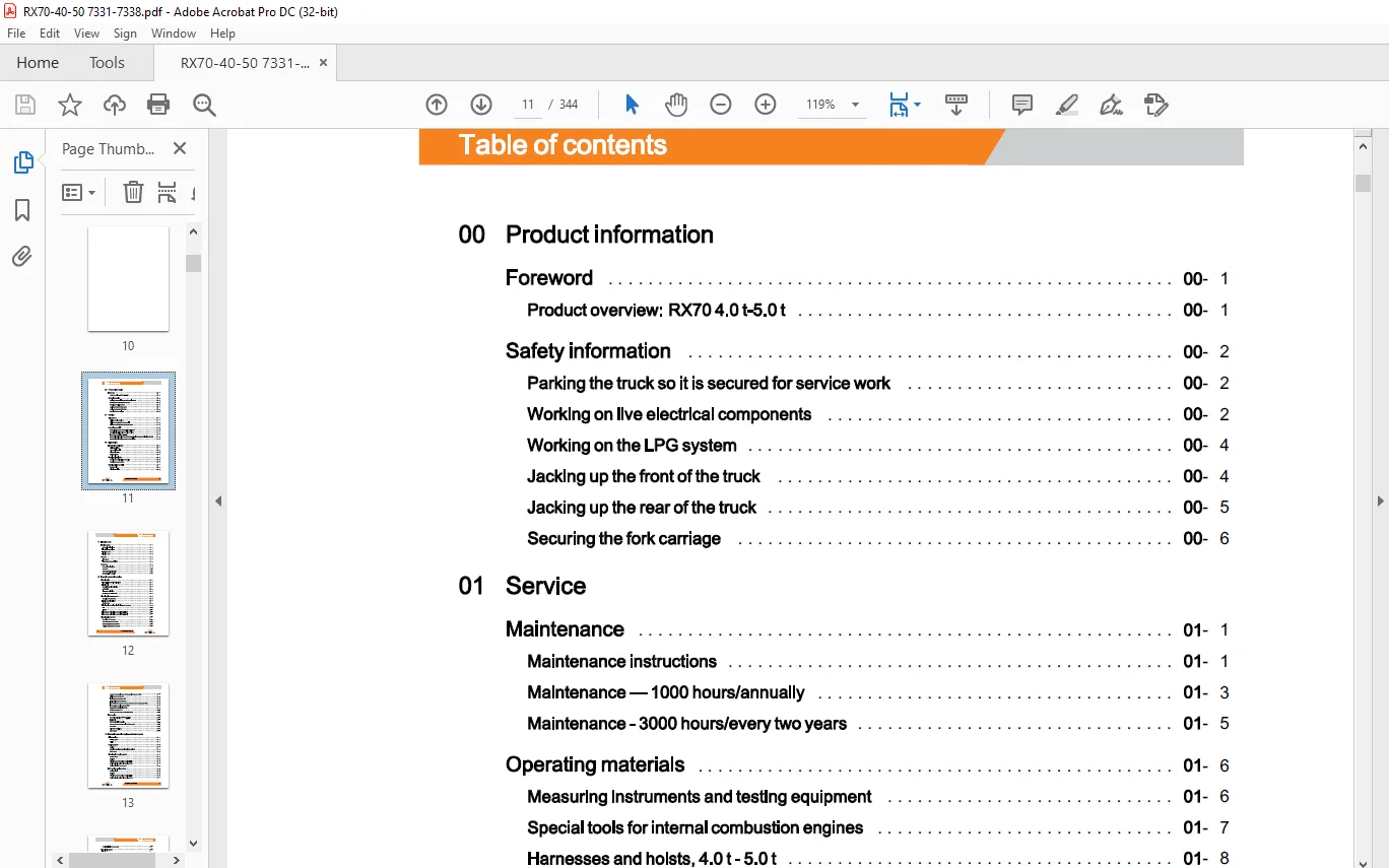
TABLE OF CONTENTS:
STILL STED Diesel LPG forklift trucks RX70-40 RX70-45 RX70-50 workshop Manual – PDF DOWNLOAD
00 Product information
Foreword
Product overview: RX70 4.0 t-5.0 t
Safety information
Parking the truck so it is secured for service work
Working on live electrical components
Working on the LPG system
Jacking up the front of the truck
Jacking up the rear of the truck
Maintenance 01
Maintenance instructions 01
Maintenance – 1000 hours/annually 01
Maintenance – 3000 hours/every two years 01
Operating materials 01
Measuring instruments and testing equipment 01
Special tools for internal combustion engines 01
Harnesses and hoists, 4.0 t- 5.0 t 01
Standardised tightening torques for standard-pitch threads and fine-pitch threads 01
Standardised tightening torques for hose fittings 01
02 Diagnostics
Introduction to DiaMon
STEDS-Navigator
CAN box diagnostics
Diagnostic set-up
Starting DiaMon
Working with DiaMon
Reading out and clearing the error list
Reading out access codes
Working using the ABE
Read error list
Clearing error lists
X 57338012001 EN – 12/2016
Table of contents
11 Electric motor
Traction motor 11
General technical data 11
Electrical connections 11
Traction motor 11
Traction motor 11
Sensors 11
Pin sensor 11
Temperature sensor KTY84 11
Generator 11
General technical data 11
Generator 11
Generator- Diesel engine 11
Generator- LPG engine 11
12 Internal combustion engine
Diesel engine 12
TCD 2.9 L4 general technical data 12
Engine unit 12
Deutz TCD 2.9 diesel engine 12
Catch plate 12
Alternator monitoring 12
Replacing the V-ribbed belt 12
Diesel engine components 12
Overview of components 12
Engine control unit ECU 12
Starter motor 12
Fuel-quantity metering unit with high-pressure pump 12
Rail 12
Injector 12
Exhaust gas recirculation, Deutz TCD 2.9-DOC 12
Exhaust gas recirculation, Deutz TCD 2.9-DPF 12
Diesel engine sensors 12
Overview of the sensors 12
Camshaft speed sensor B401 12
Crankshaft speed sensor B402 12
Coolant temperature sensor B43 12
Sensor for charge air pressure/charge air temperature B48
Rail pressure sensor B49
Fuel low-pressure sensor B51
Engine-oil pressure sensor B6
Exhaust-gas back pressure sensor upstream of the turbocharger 0B60
Exhaust-gas mass flow sensor 0B84
Actuator for butterfly valve 0Y 18
MPROP actuator 0Y19
Actuator for exhaust gas recirculation 0Y20
LPG engine
General technical data-VW 3.61 LPG
Engine unit
VW VR6 3.6 ltr LPG engine
Spacer washer between engine and generator
Catch plate
Alternator monitoring
Starter motor
Internal combustion engine -Attachment parts
Air intake/filter
Air filter system
Air filter
Cooling system
Coolant
Checking, topping up and bleeding the coolant
Water pump
Diesel engine cooling system
Cooling circuit
Radiator
V-engine and brake resistor cooling circuit
Cooling circuit, variant with heating system
Cooling circuit for the converter
LPG engine cooling system
Cooling circuit
Radiator
V-engine and brake resistor cooling circuit
Cooling circuit, variant with heating system
XII 57338012001 EN – 12/2016
Table of contents
Cooling circuit for the converter 13
Diesel fuel system 13
Fuel system 13
Fuel filter 13
Low fuel warning threshold 13
LPG system 13
LPG system 13
Evaporator module 13
Suction module 13
MAP/MAT sensor 0B6 13
Actuator unit 13
Gas shut-off valve unit 13
Gas shut-off valve monitoring 13
Shut-down due to lack of gas 13
Maintenance and test specifications 13
Testing for leaks in the LPG system 13
Testing CO level in exhaust gases 13
Servicing the LPG filter 13
Servicing the 30-bar high-pressure relief valve 13
Safety valve – 1. 7 bar 13
Evaporator – maintenance 13
14 Internal combustion engine – exhaust system
Deutz TCD 2.9 DOC exhaust system 14
Exhaust system 14
Deutz TCD 2.9 DPF exhaust system 14
Continuous regeneration 14
Standstill regeneration 14
Exhaust system 14
Sensors in the DPF system 14
VW 3.6-1 LPG exhaust system 14
Exhaust system 14
22 Mechanical drive axle
Drive axle EC501 22
General technical data Carraro EC 50 I 22
Drive axle 22
Table of contents
Removing/installing the drive axle 22
Drive wheel unit 22
Service brake 22
Removing/installing the service brake 22
Differential gearbox and brake 22
Removal of the differential gearbox and brake 22
Installation of the differential gearbox and brake 22
Basic setting of the brake system 22
Testing the brake system 22
30 Chassis, bodywork and fittings
Chassis 30
Working with gas springs 30
Counterweight 30
Counterweight 30
42 Steering system
Hydraulic steering 42
General technical data 42
Steering system 42
Steering – error detection 42
Steering unit 42
Priority valve 42
Steering axle 42
General technical data 42
Swing axle 42
Removing/installing the swing axle 42
Wheel hub 42
Steering angle 42
Tie rod 42
Axle stub 42
50 Operating devices
Drive and brake actuation 50
Brake actuation 50
Changing the brake cable for the service brake 50
Brake cable change, handbrake 50
Actuating force of the handbrake 50
XIV 57338012001 EN – 12/2016
Table of contents
Parking brake switch 1 S3 50
Brake sensor 1 B2 50
Accelerator- single-pedal 50
Dual pedal 50
Accelerator- dual pedal, generation 2 50
Operating devices 50
Joystick 4Plus 50
Axle assignment – Joystick 4Plus 50
Generation 2 mini-lever 50
Axle assignment – the mini-lever 50
Joystick 50
Axle assignment – Joystick 50
Tip switch 50
Axle assignment – fingertip switch 50
56 Display elements
Operating console 56
Turn indicator module for the drive direction, generation 2 56
Direction indicator module (Fabli) 56
Display 56
Display and operating unit, generation 2 (ABE 2) 56
ABE 2 Installation and removal 56
60 Electrical enclosure
General 60
General technical data 60
Overview of electrical components 60
Overview of the controllers 60
Software compatibility 60
PAN process 60
Parameter management 60
Error ring buffer 60
Traction motor temperature monitoring 60
Temperature monitoring for the traction converter 60
Availability of drive mode and driving behaviour 60
Driving mode – driving behaviour Description 60
Stopping on a slope 60
Blue-Q=IQ 60
57338012001 EN – 12/2016 XV
Table of contents
Electrical checks 60
Intermediate circuit 60
Insulation measurement 60
Wiring 60
CAN bus system 60
CAN bus connections 60
Power cables 60
Maintenance guidelines for power cables 60
Repair – Contact elements 60
Electrical system 60
Fusebox 60
Fuses in the fuse box 60
Relays in the fuse box 60
Other components 60
Option Board 60
CAN-Power-Port (CPP) 60
CPP 1/CPP 3 60
CPP2B 60
Relay-Power-Port 60
64 Electronic controls
Truck control unit 64
Truck Control Unit 2 (TCU 2) 64
Truck Control! Unit (TCU) Removal and installation 64
Converter 64
Converter 64
Converter L TI 64
Converter SVAC 64
Converter Removal and installation 64
Converting from L TI to SVAC 64
Brake resistor 64
69 Batteries and accessories
Starter battery 69
Starter battery G1 69
Working with batteries 69
XVI 57338012001 EN – 12/2016
Table of contents
70 Hydraulics
General 70
General technical data 70
Depressurising the hydraulics 70
Operating speeds for lifting 70
Operating speeds for lowering 70
Operating speeds for tilting 70
Safety check 70
Forward tilt safety test 70
Lowering safety test 70
Safety checks of hose assembly 70
Basic hydraulics 70
Basic hydraulics 70
Fan control valve 70
Steering hydraulics 70
Working hydraulics 70
Variable displacement pump 70
Pump regulator 70
Variable displacement pumpRemoval and installation 70
Hydraulic tank 70
Hydraulic oil 70
Intake filter 70
Return filter 70
Breather 70
High-pressure filter 70
Bolted joint 70
Conical nipple fittings (CNF) 70
71 Working hydraulics
Tilt cylinder 71
Mast tilt 71
Tilt cylinder Removal and installation 71
Changing the set of seals, 2000-5000 kg 71
Changing the set of seals 5000 kg – LSP 600 71
Auxiliary hydraulics 71
Operating speeds of the attachments 71
Second operating function for attachments 71
57338012001 EN – 12/2016 XVII
Table of contents
Clamp locking mechanism with servo hydraulics 71
Accumulator 71
Accumulator 71
Checking the accumulator 71
76 Valves
Servo hydraulics 76
General technical data 76
Directional control valve block 76
Removing and installing the valve block 76
80 Load lift system
Mast bearings 80
Carraro EC50 and EC50I mast bearings 80
81 Lift mast
Lift mast 81
General technical data 81
Hose safety valve of triplex mast 81
Support roller play ( 150) 81
Load chains – Checking and cleaning 81
Run-out barrier 81
Working on lift masts 81
Lift mast – Removal 81
Lift mast- Installation 81
Telescopic lift mast 81
Telescopic lift mast (150) 81
Adjusting the load chains Telescopic lift mast (150) 81
Removing the support rollers in the lift mast 81
Assembling the lift mast after replacing the support rollers 81
Triple mast 81
Triple mast ( 150) 81
Adjusting the outer load chains Triple mast ( 150) 81
Load chain adjustment midpoint Triple mast ( 150) 81
Lift cylinder 81
Lift jack 81
Working on lift cylinders 81
Outer cylinder 81
84 Load support
Fork carriage
Annex
Fork carriage – Removing in an upwards direction
Fork carriage – Removing in a downwards direction
X Circuit diagrams
Hydraulics
Servo hydraulics
Questions? Email us: [email protected]
https://vimeo.com/856144963?share=copy
PLEASE NOTE:
- This is the same manual used by the dealers to diagnose and troubleshoot your vehicle
- You will be directed to the download page as soon as the purchase is completed. The whole payment and downloading process will take anywhere between 2-5 minutes
- Need any other service / repair / parts manual, please feel free to contact [email protected] . We still have 50,000 manuals unlisted
S.M