Still STED Diesel trucks and LPG trucks RX7020 RX7025 RX7025 600 RX70 30 RX70 30 600 RX70 35 RX70 35 600 workshop Manual – PDF DOWNLOAD
$28.95
Still STED Diesel trucks and LPG trucks RX7020 RX7025 RX7025 600 RX70 30 RX70 30 600 RX70 35 RX70 35 600 workshop Manual – PDF DOWNLOAD
Description
Still STED Diesel trucks and LPG trucks RX7020 RX7025 RX7025 600 RX70 30 RX70 30 600 RX70 35 RX70 35 600 workshop Manual – PDF DOWNLOAD
FILE DETAILS:
Still STED Diesel trucks and LPG trucks RX7020 RX7025 RX7025 600 RX70 30 RX70 30 600 RX70 35 RX70 35 600 workshop Manual – PDF DOWNLOAD
Language : English
Pages : 368
Downloadable : Yes
File Type : PDF
DESCRIPTION:
Still STED Diesel trucks and LPG trucks RX7020 RX7025 RX7025 600 RX70 30 RX70 30 600 RX70 35 RX70 35 600 workshop Manual – PDF DOWNLOAD
Product overview: RX70 20-35
- Trucks with a load centre of gravity of 600 in load capacity classes 2.0 to 3.0 t.
- Temperature sensor PT1000
- Accelerator pedal, generation 2 New engines in diesel trucks:
- New STILL Driveline drive motor with industrial diesel engine D24KDO.
- Increased torque means more power for accelerating, pushing, pulling and driving up inclines.
- Smooth driving behaviour with improved responsiveness and increased driving dynamics.
- Increased maximum lifting speed to almost 0.7 m/s.
- Noise level reduced to approx. 3 dB, corresponding to an approximately 50% reduction in perceived noise in comparison to the previous model.
- No toothed belt for the valve control, negating the need to replace the toothed belt.
- New engine mount
- Fan motor with integrated fan control valve
- New generator with increased nominal capacity
- Larger starter battery
IMAGES PREVIEW OF THE MANUAL:
TABLE OF CONTENTS:
Still STED Diesel trucks and LPG trucks RX7020 RX7025 RX7025 600 RX70 30 RX70 30 600 RX70 35 RX70 35 600 workshop Manual – PDF DOWNLOAD
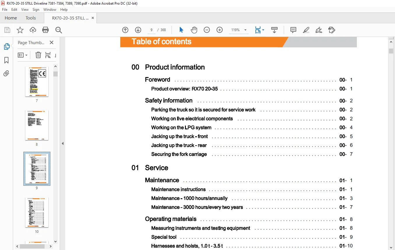
00 Product information
Foreword
Product overview: RX70 20-35
Safety information
Parking the truck so it is secured for service work
Working on live electrical components
Working on the LPG system
Jacking up the truck- front
Jacking up the truck – rear
Securing the fork carriage
01 Service
Maintenance 01
Maintenance instructions 01
Maintenance – 1000 hours/annually 01
Maintenance – 3000 hours/every two years 01
Operating materials 01
Measuring instruments and testing equipment 01
Special tool 01
Harnesses and hoists, 1.0 t- 3.5 t 01
Standardised tightening torques for standard-pitch threads and fine-pitch threads 01
Standardised tightening torques for hose fittings 01
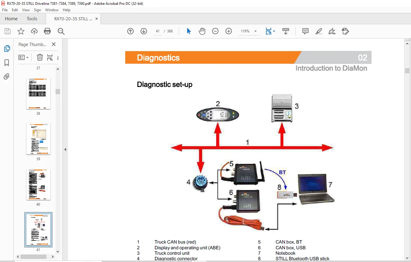
02 Diagnostics
Introduction to DiaMon
STEDS-Navigator
Diagnostics service box
Diagnostic set-up
Starting DiaMon
Working with DiaMon
Error list via DiaMon
Reading out access codes
Working using the ABE
Read error list
VIII 57368012001 EN – 08/2018
Table of contents
11 Electric motor
Traction motor 11
General technical data 11
Electrical connections 11
Traction motor 11
Sensors 11
Rev sensor 11
Temperature sensor 11
Generator – Diesel 11
General technical data 11
Generator 11
Generator – LPG 11
General technical data 11
Alternator 11
Alternator removal-installation 11
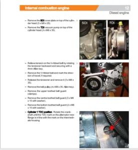
12 Internal combustion engine
Diesel engine 12
General technical data for D24KDO 12
Diesel engine D24KDO 12
Engine unit 12
Engine mount 12
Catch plate 12
Diesel engine components 12
Overview of components 12
Alternator monitoring 12
Starter motor 12
Replacing the V-belt 12
Diesel engine sensors 12
Overview of the sensors 12
LPG engine 12
General technical data VW 2.01 SPI 12
VW LPG – 2.0 litre BEF 12
Engine control unit VW 2.0I SPI 12
Starter motor 12
Starter ring gear 12
57368012001 EN – 08/2018 IX
Table of contents
Alternator 12
Alternator monitoring 12
13 Internal combustion engine -Attachment parts
Air intake/filter 13
Air filter 13
Air filter system, diesel 13
Air filter system, LPG 13
Cooling system 13
Diesel cooling circuit 13
LPG cooling circuit 13
Water pump 13
Coolant 13
Diesel fuel system 13
Fuel system 13
Fuel filter 13
Low fuel warning threshold 13
LPG system 13
LPG system 13
Evaporator module 13
Removing and installing the evaporator 13
Suction module 13
MAP/MAT sensor 0B6 13
Actuator unit 13
Gas shut-off valve monitoring 13
Shut-down due to lack of gas 13
Maintenance and test specifications 13
Testing for leaks in the LPG system 13
Testing CO level in exhaust gases 13
Servicing the LPG filter 13
Servicing the 30-bar high-pressure relief valve 13
14 Internal combustion engine- exhaust system
Exhaust system – Diesel 14
Exhaust system 14
Exhaust system – Particle filter 14
General technical data – Eberspacher 14
X 57368012001 EN – 08/2018
Table of contents
Structure of the Eberspacher particle filter 14
7.5 kW Eberspacher particle filter 14
Regeneration 14
Maintenance instructions 14
Exhaust system – LPG 14
Exhaust system 14
Lambda control system 14
Lambda sensor 14
Three-way catalytic converter 14
22 Mechanical drive axle
Drive axle 8.30 22
General technical data, Carraro 8.30 22
Drive axle 22
Wheel drive 22
Checking the oil level, changing the oil 22
Removal and installation of the drive axle 22
Traction motor 22
Service brake 22
Differential gearbox 22
30 Chassis, bodywork and fittings
Chassis 30
Floorplate 30
Working with gas springs 30
Counterweight 30
Counterweight 30
42 Steering system
Hydraulic steering 42
General technical data 42
Steering hydraulics 42
Steering – error detection 42
Steering unit 42
Steering wheel and steering column 42
Steering column 42
Steering axle 42
General technical data 42
57368012001 EN – 08/2018 XI
Table of contents
Swing axle 42
Swing axle Removal and installation 42
Wheel hub 42
Steering angle 42
Tie rod 42
Axle stub 42
50 Operating devices
Accelerator pedal 50
Accelerator pedal, generation 2 50
Accelerator- dual pedal 50
Brake actuation 50
Brake actuator 50
Brake sensor 1 B2 50
Parking brake switch 1 S3 50
Replacing the brake cable 50
Actuating force of the handbrake 50
Hydraulic actuation 50
Joystick 4Plus 50
Axle assignment – Joystick 4Plus 50
Generation 2 mini-lever 50
Axle assignment – the mini-lever 50
Tip switch 50
Axle assignment – fingertip switch 50
56 Display elements
Operating console 56
Turn indicator module for the drive direction, generation 2 56
Display 56
Display and operating unit, generation 2 (ABE 2) 56
ABE 2 Installation and removal 56
60 Electrics/electronics
General 60
General technical data 60
Overview of the controllers 60
Overview of electrical components 60
Software compatibility 60
XII 57368012001 EN – 08/2018
PAN process
Parameter management
Error ring buffer
Traction motor temperature monitoring
Temperature monitoring for the traction converter
Availability of drive mode and driving behaviour
Driving mode – driving behaviour Description
Blue-Q=IQ
Electrical testing
Intermediate circuit
Insulation measurement
Wiring
CAN bus system
CAN bus connections
Power cables
Maintenance guidelines for power cables
Repair – Contact elements
Electrical system
Fusebox
Fuses in the fuse box
Relays in the fuse box
Sensor system
Vertical lift mast position
Installing the lift mast-vertical position
Tilt angle sensor 7B46
Load measurement
Load measurement pressure sensor
Additional electrical installation
Option Board
CAN-Power-Port (CPP)
CPP 1/CPP3
CPP2B
Soot CPP (CPP5)
Relay-Power-Port
Cooling system
Electrical converter cooling system
Table of contents
57368012001 EN – 08/2018 XIII
Table of contents
64 Electronic controls
Truck control unit 64
Truck Control Unit 2 (TCU 2) 64
Truck Control! Unit (TCU) Removal and installation 64
Converter 64
SVAC converter 64
Removing and installing the converter 64
Location of brake resistor in the truck 64
Brake resistor 64
69 Batteries and accessories
Starter battery 69
Working with batteries 69
Starter battery, diesel 69
Starter battery, LPG 69
70 Hydraulics
General 70
General technical data 70
Releasing the pressure from the hydraulics 70
Operating speeds for lifting 70
Operating speeds for lowering 70
Tilt operating speeds 70
Safety check 70
Forward tilt safety test 70
Lowering safety test 70
Safety checks of hose assembly 70
Basic hydraulics 70
Basic hydraulics, diesel engines 70
Working hydraulics, diesel engines 70
Fan motor controller, diesel engines 70
Fan motor with fan control valve 70
Basic hydraulics, LPG engines 70
Working hydraulics, LPG engines 70
Fan motor controller, LPG engines 70
Fan control valve 70
Variable displacement pump 70
STILL
XIV 57368012001 EN – 08/2018
Table of contents
Pump regulator 70
Variable pumpRemoval and installation 70
Hydraulic tank 70
Hydraulic oil 70
Return filter 70
Breather 70
Intake filter 70
High-pressure filter 70
High-pressure filter 70
Conical nipple fittings (CNF) 70
Bolted joint 70
71 Working hydraulics
Tilt cylinder 71
Mast tilt 71
Removing/installing the tilt cylinder 71
Changing the set of seals, 2000-5000 kg 71
Auxiliary hydraulics 71
Attachments 71
Second operating function for attachments 71
Accumulator 71
Accumulator 71
Checking the accumulator 71
76 Valves
Servo hydraulics 76
General technical data 76
Directional control valve block 76
Directional control valve function Lifting 76
Directional control valve function Lowering 76
80 Load lift system
Mast bearing 80
Carraro Malis mast bearing 80
81 Lift mast
Lift mast 81
General technical data 81
57368012001 EN – 08/2018 XV
Table of contents
Hose safety valve of triplex mast 81
Support roller play ( 108/117 /130) 81
Load chains – Checking and cleaning 81
Run-out barrier 81
Working on lift masts 81
Lift mast – Removal 81
Lift mast- Installation 81
Telescopic lift mast 81
Telescopic lift mast ( 130 MaLiS) 81
Adjusting the load chains Telescopic lift mast ( 130 MaLiS) 81
Removing the support rollers in the lift mast 81
Assembling the lift mast after replacing the support rollers 81
Outer load chains and chain rollers 81
Ni Ho lift mast 81
NiHo lift mast (130 MaLiS) 81
Adjusting the load chains NiHo lift mast (130 MaLiS) 81
Triplex lift mast 81
Triple lift mast ( 130 MaLiS) 81
Adjusting the outer load chains Triple lift mast ( 130 MaLiS) 81
Adjusting the middle load chain Triple lift mast ( 130 MaLiS) 81
Removing the support rollers 81
Assembling the lift mast after replacing the support rollers 81
Outer load chains and chain rollers 81
Middle load chain and chain roller 81
Lift cylinder 81
Lift jack 81
Working on lift cylinders 81
Removing and installing the outer cylinders 81
Disassembling/assembling the outer cylinder 81
Middle cylinder 81
Disassembling/assembling the middle cylinder 81
End position damping, type B (bottom) 81
End position damping, type A (top) 81
84 Load support
Fork carriage – 2500-3500 84
Removing and installing the fork carriage 84
XVI 57368012001 EN – 08/2018
Fork wear protection
Annex
99 Circuit diagrams
Hydraulics
Servo hydraulics, diesel engines
Servo hydraulics, LPG engines
Customer Support: [email protected]
https://vimeo.com/856662202?share=copy
PLEASE NOTE:
- This is the SAME exact manual used by your dealers to fix your vehicle.
- The same can be yours in the next 2-3 mins as you will be directed to the download page immediately after paying for the manual.
- Any queries / doubts regarding your purchase, please feel free to contact [email protected]
S.M