Trusted Business
Verified & Licensed
Virus Free Files
100% Safe Downloads
Secure Payment
SSL Protected
Instant Delivery
Available Immediately
STILL STED Electric forklift truck RX20-15-20, RX60-16-20 Workshop Manual – PDF DOWNLOAD
$28.95
STILL STED Electric forklift truck RX20-15-20, RX60-16-20 Workshop Manual – PDF DOWNLOAD
Instant PDF Download
Available immediately
Save to Your Device
Download & keep forever
Antivirus Scanned
100% virus-free
Trusted Worldwide
175,000+ customers
Description
STILL STED Electric forklift truck RX20-15-20 RX60-16-20 Workshop Manual – PDF DOWNLOAD
FILE DETAILS:
STILL STED Electric forklift truck RX20-15-20 RX60-16-20 Workshop Manual – PDF DOWNLOAD
Language : English
Pages : 458
Downloadable : Yes
File Type : PDF
DESCRIPTION:
STILL STED Electric forklift truck RX20-15-20 RX60-16-20 Workshop Manual – PDF DOWNLOAD
Foreword Improved properties:
• Enhanced discharge indicator and consump tion display
- New components:
- Joystick 4Plus
- Push-up roof panel
- Metal brand emblem
- Lighting on top of the overhead guard
- • Diagnostic connector (Group connector) in the front structure
New features from 2012
• New truck type RX20-14 (6209) New components:
• Generation 2 MCU
• Drive axle AE 18-07 New features from 2009-Facelift Step1 and Step2 Improved properties:
• Ergonomic driver’s workstation
• Drive mode Blue-Q New components:
• Generation 2 mini-lever Generation 2 display and operating unit Electric parking brake
• Load measurement
• Mast vertical position
• Hydraulics blocking function in accordance with EN ISO 3691-1
IMAGES PREVIEW OF THE MANUAL:
TABLE OF CONTENTS:
STILL STED Electric forklift truck RX20-15-20 RX60-16-20 Workshop Manual – PDF DOWNLOAD
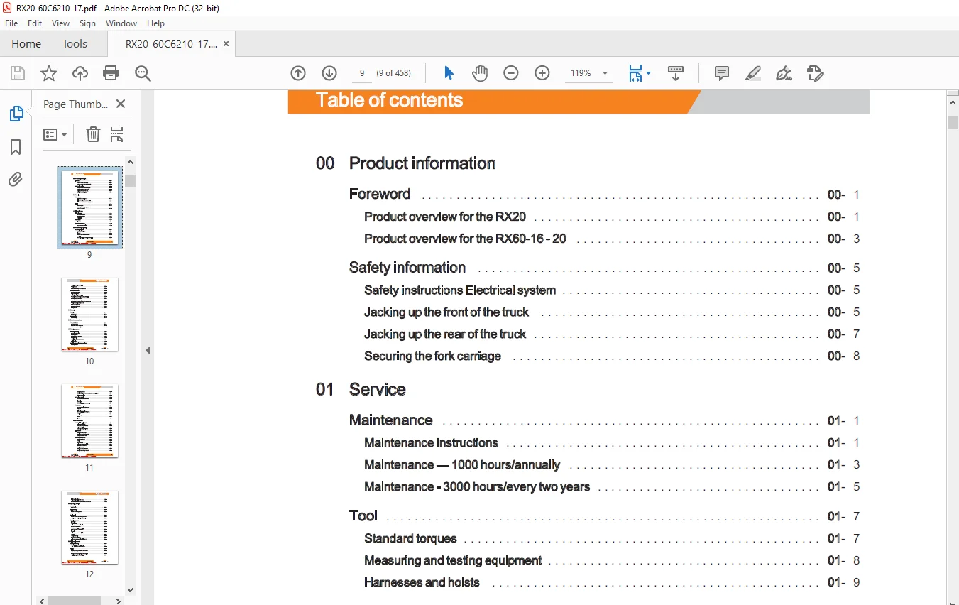
Table of contents
00 Product information
Foreword 00- 1
Productoverview forthe RX20 00- 1
Product overview forthe RX60-16-20 00- 3
Productoverview forthe RX20 00- 1
Product overview forthe RX60-16-20 00- 3
Safetyinformation 00- 5
Safety instructions Electrical system 00- 5
Jacking up the frontofthetruck LL 00- 5
Jackinguptherearofthetruck lL 00- 7
Securing theforkcarriage 00- 8
Safety instructions Electrical system 00- 5
Jacking up the frontofthetruck LL 00- 5
Jackinguptherearofthetruck lL 00- 7
Securing theforkcarriage 00- 8
01 Service
Maintenance 01- 1
Maintenance instructions LL 01-1
Maintenance — 1000 hours/annually 01- 3
Maintenance – 3000 hours/everytwoyears 01- 5
Maintenance instructions LL 01-1
Maintenance — 1000 hours/annually 01- 3
Maintenance – 3000 hours/everytwoyears 01- 5
Tool 01-7
Standardtorques 0-7
Measuring and testingequipment 01- 8
Harnessesandhoists 01-9
Standardtorques 0-7
Measuring and testingequipment 01- 8
Harnessesandhoists 01-9
11 Electric motor
Tractionmotor 11-1
Generaltechnicaldata 11-1
Electricalconnections 11-1
Tractiondrive 11- 2
Generaltechnicaldata 11-1
Electricalconnections 11-1
Tractiondrive 11- 2
RevSensor 11- 4
Pin Sensor 11- 4
Pin Sensor 11- 4
Temperature Sensor 11- 6
Temperature sensor KTY84 11- 6
Temperature sensor KTY84 11- 6
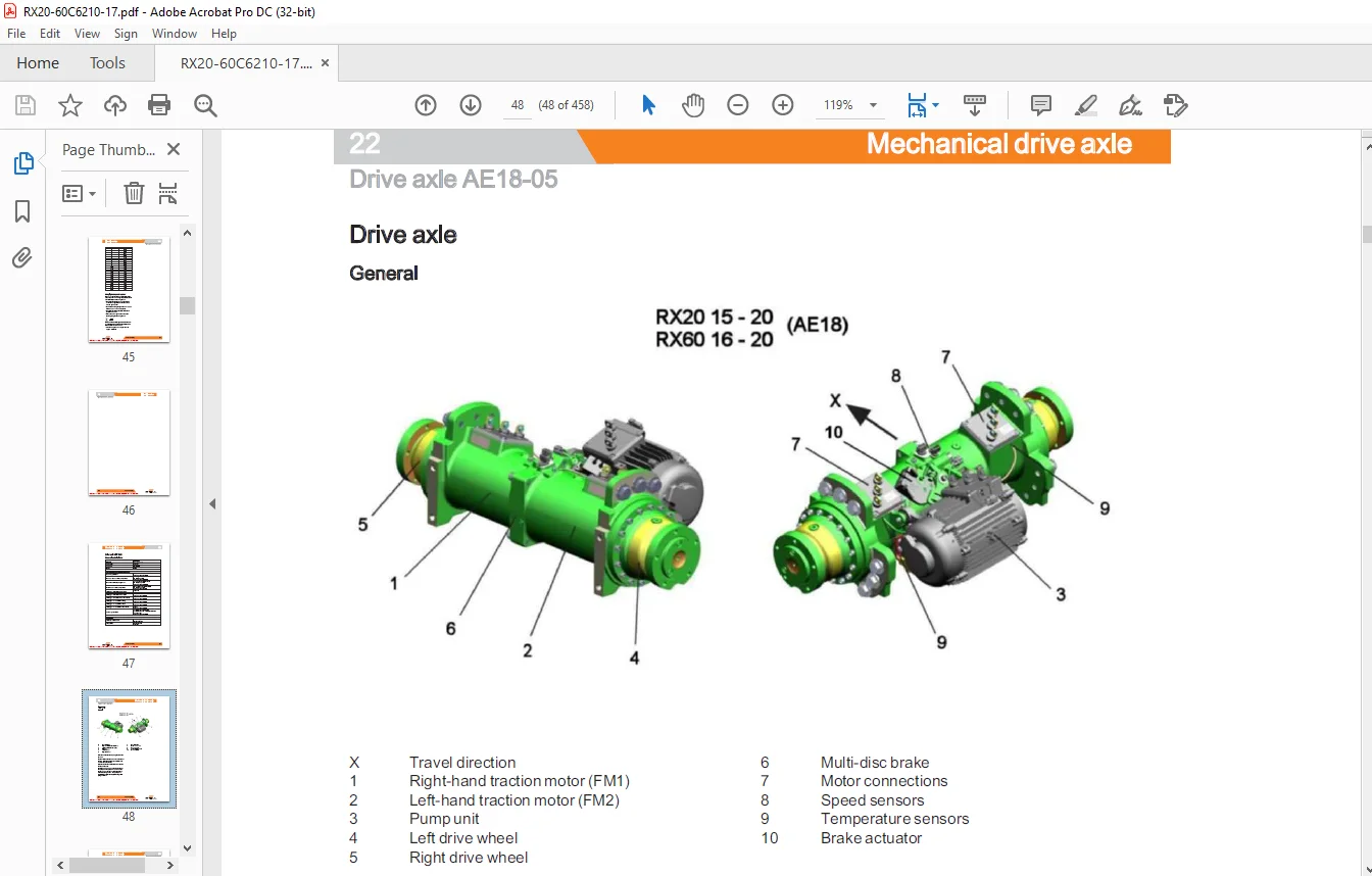
22 Mechanical drive axle
Driveaxle AE18-05 22-1
Generaltechnicaldata 22- 1
Drive axle 22- 2
Drive axle removal andinstallation 22- 3
Wheeldrive 22- 7
Removal/installation of the drive wheelunit 22- 8
Generaltechnicaldata 22- 1
Drive axle 22- 2
Drive axle removal andinstallation 22- 3
Wheeldrive 22- 7
Removal/installation of the drive wheelunit 22- 8
THN y
STILL
STILL
TRIAL MODE – a valid license will remove this message See the keywords property of this PDF for more information
Table of contents
Table of contents
Repairing the drive wheelunit
Tractionmotor
Tractionmotor
Removing/installing the servicebrake
Drive axle AE18-07
Generaltechnicaldata
Driveaxle AE18-07
Removingthedrivewheelunit
Changing the shaft seal on the drive wheelunit
Refitting the drivewheelunit
Traction motor — Removing therotor
Replacing the traction motor bearing and shaftseal
Traction motor – Installing therotor
Dismantlingthebrake
Assemblingthebrake iL
Filingwithoil
31 Chassis
Chassis
Batterydoor
Batterydoor
Counterweight
Counterweight
34 Driver’s compartment
Overheadguard
Overheadguard
Removing the overheadguard
Overheadguard
Removing the overheadguard
Installingthe overheadguard
42 Steering system
Hydraulicsteering
Generaltechnicaldata
Steeringsystem LL
Steering—errordetection
Steeringunit
6S3 diaphragm pressureswitch
Priorityvalve
Generaltechnicaldata
Steeringsystem LL
Steering—errordetection
Steeringunit
6S3 diaphragm pressureswitch
Priorityvalve
Steering wheel with steeringcolumn
Steeringcolumn LLL
TRIAL MODE – a valid license will remove this message See the keywords property of this PDF for more information
Table of contents
Table of contents
Steeringangle sensor LLL 42-13
Steering angle-dependent handling performance —CSC 42-15
CSC—functionaltest 42-16
Steeringturntable 42-19
General technical dataFifthwheel 42-19
Fifthwheel 42-20
Curveswitch 42-20
Removing/installing the fifthwheel 42-21
Swingaxle 42-25
General technicaldata Swingaxle 42-25
Swingaxle 42-26
Swingaxlecurveswitch 42-27
Removing/installingthe swingaxle 42-28
Wheelhub 42-31
Steeringangle 42-33
Tierod 42-34
Axlestub 42-35
49 Brake system
Mechanical servicebrake 49- 1
Servicebrake AE18-05 LL 49- 1
Brake cable changer AE18-05 49- 3
Servicebrake AE18-07 LL 49- 5
Brake cable changer AE18-07 49- 6
Servicebrake AE18-05 LL 49- 1
Brake cable changer AE18-05 49- 3
Servicebrake AE18-07 LL 49- 5
Brake cable changer AE18-07 49- 6
Handbrake 49- 8
Handbrake cablechanger 49- 8
Actuating force ofthehandbrake 49- 9
Parking brake switch 1S3 49-10
Handbrake cablechanger 49- 8
Actuating force ofthehandbrake 49- 9
Parking brake switch 1S3 49-10
Electricparkingbrake 49-12
Electricparkingbrake 49-12
Function 49-13
Causeandeffect 49-15
Design and systemdescription 49-17
Maintenanceinstructions LLL 49-19
Checkingthebrake 49-20
Calibration and functionaltest 49-22
Changing the parkingbrakecable 49-25
Electricparkingbrake 49-12
Function 49-13
Causeandeffect 49-15
Design and systemdescription 49-17
Maintenanceinstructions LLL 49-19
Checkingthebrake 49-20
Calibration and functionaltest 49-22
Changing the parkingbrakecable 49-25
oT y
STILL
STILL
TRIAL MODE – a valid license will remove this message See the keywords property of this PDF for more information
Table of contents
Table of contents
Limitpositionswitch
Drive unit Installationandremoval
Drive unit Installationandremoval
Central lubrication device Installationand removal
50 Operating devices
Brakepedal
Brake sensor
Singlepedal
Accelerator—single-pedal LL
Deadmanswitch7S13
Accelerator—single-pedal LL
Deadmanswitch7S13
Dualpedal
Accelerator—dual pedal 2nd generation
Accelerator—dual pedal 2nd generation
Accelerator —dual pedal 1stgeneration
Operatingdevices
Handlever
Joystick4Plus LL
Axle assignment -Joystick4Plus
Generation2mini-lever
Generation 2 mini-leverActuation
Axle assignment-themini-lever
Tipswitch
Axle assignment -fingertipswitch
Joystick LL
Joystickoperation LL
Generation Tmini-lever
Handlever
Joystick4Plus LL
Axle assignment -Joystick4Plus
Generation2mini-lever
Generation 2 mini-leverActuation
Axle assignment-themini-lever
Tipswitch
Axle assignment -fingertipswitch
Joystick LL
Joystickoperation LL
Generation Tmini-lever
Axle assignment – Joystick, minilever1 LL
56 Display elements
Operatingconsole
Direction indicatormodule (Fabli)
Direction indicatormodule (Fabli)
Drive direction tum indicatordisplay
Display
Display operating unit (ABE 1) Generation1
ABE 1 Installationandremoval
Display operating unit (ABE 2) Generation2
Display operating unit (ABE 1) Generation1
ABE 1 Installationandremoval
Display operating unit (ABE 2) Generation2
ABE 2 Installationandremoval
TRIAL MODE – a valid license will remove this message See the keywords property of this PDF for more information
Table of contents
Table of contents
60 Electrics / Electronics
General 60- 1
General technicaldata-48Volt 60- 1
General technicaldata-80Volt 60- 3
Overviewofthecontrollers 60- 4
Electrical system 60- 5
Electricalcomponents 60- 5
Switching on procedure for the electricalsystem 60- 7
Software compatibility 60-12
PAN DrOCESS «oo 60-13
Parametermanagement LLL 60-14
Errorring buffer 60-15
Intermediate circuit 60-16
Insulation testing forelectrictrucks 60-18
Insulation testingonthedrivebattery 60-20
Componentinsulationtesting 60-21
Temperature monitoring for the traction motor-48V 60-24
Temperature monitoring for the traction motor-80V 60-26
Temperature monitoring for the traction motor converter 60-27
Pump motor temperature monitoring 60-28
Temperature monitoring for the pump motorconverter 60-30
Available driving behaviour 60-31
Drive mode — driving behaviour Description 60-31
Blue-Q=1Q 60-33
WINING 60-35
CANDus system 60-35
CANbusconnections 60-37
Powercables 60-39
Maintenance guidelines forpowercables 60-40
Repair-Contactelements 60-40
CANDus system 60-35
CANbusconnections 60-37
Powercables 60-39
Maintenance guidelines forpowercables 60-40
Repair-Contactelements 60-40
Electrical system 60-42
Fuse boX 60-42
FUSES 60-42
Fuse plateUntil April2005 60-44
FusesUntil April2005 60-46
Contactor 60-47
Fuse boX 60-42
FUSES 60-42
Fuse plateUntil April2005 60-44
FusesUntil April2005 60-46
Contactor 60-47
THN y
STILL
STILL
TRIAL MODE – a valid license will remove this message See the keywords property of this PDF for more information
Table of contents
Table of contents
Sensorsystem
Vertical lift mast positon
Tiltanglesensor7B46
Tiltangle sensorparameters
Installation of the vertical lift mast position
Loadmeasurement LL
Vertical lift mast positon
Tiltanglesensor7B46
Tiltangle sensorparameters
Installation of the vertical lift mast position
Loadmeasurement LL
Load measurementpressure Sensor LL
Additional electrical installations
7A21converterPCB
OptionBoard
CAN-Power-Port (CPP)
CPP1/CPP 3
7A21converterPCB
OptionBoard
CAN-Power-Port (CPP)
CPP1/CPP 3
CPP2/CPP4
CPP battery carrier (CPP5)
Relay-Power-Port
CPP battery carrier (CPP5)
Relay-Power-Port
64 Electronic controls
Traction and working hydraulicscontrol
Main Control Unit(MCU)}
MCUwithservohydraulics
MCUgeneration2 i
Main Control Unit (MCU) Removal and installation
SupplyUnit (SU)
Supply Unit (SU) Removal and installation
Main Control Unit(MCU)}
MCUwithservohydraulics
MCUgeneration2 i
Main Control Unit (MCU) Removal and installation
SupplyUnit (SU)
Supply Unit (SU) Removal and installation
Converter
Inverters
Converter LAC-48/80Volt
Converter SAC-48Volt
Inverters
Converter LAC-48/80Volt
Converter SAC-48Volt
Converter-removalandinstallation
69 Batteries and accessories
Battery
Batteryplug
Maintenance guidelines for applianceplugs
Repair – Battery male connectorcontacts
Batteryplug
Maintenance guidelines for applianceplugs
Repair – Battery male connectorcontacts
Working withreducersleeves
TRIAL MODE – a valid license will remove this message See the keywords property of this PDF for more information
Table of contents
Table of contents
Dischargeindicator 69- 9
2014 dischargeindicator LL 69-10
2014 dischargeindicator LL 69-10
70 Hydraulics
General 70- 1
Generaltechnicaldata 70- 1
Depressurisingthe hydraulics 70- 2
Liftingoperatingspeeds 70- 4
Operating speeds forlowering 70- 4
Tilingoperatingspeeds 70- 5
Generaltechnicaldata 70- 1
Depressurisingthe hydraulics 70- 2
Liftingoperatingspeeds 70- 4
Operating speeds forlowering 70- 4
Tilingoperatingspeeds 70- 5
Safetycheck 70- 7
Forwardftiltsafetytest 70- 7
Loweringsafetytest 70- 7
Safety checks ofhoseassembly 70- 8
Forwardftiltsafetytest 70- 7
Loweringsafetytest 70- 7
Safety checks ofhoseassembly 70- 8
Basichydraulics 70- 9
Basichydraulics 70- 9
Steering hydraulics 70-10
Working hydraulics 70-11
Hydraulictank 70-12
Hydraulicoil 70-12
Returnlinefilter 70-13
Breatherfilter 70-14
Suction filter 70-15
High-pressurefilter 70-16
Conical nipple fittings (CNF) 70-17
Boltedjoint 70-17
Basichydraulics 70- 9
Steering hydraulics 70-10
Working hydraulics 70-11
Hydraulictank 70-12
Hydraulicoil 70-12
Returnlinefilter 70-13
Breatherfilter 70-14
Suction filter 70-15
High-pressurefilter 70-16
Conical nipple fittings (CNF) 70-17
Boltedjoint 70-17
71 Working hydraulics
Pumpunit 71-1
Generaltechnicaldata 71-1
Pumpunit 71- 2
Electricalconnections LL 71- 4
Pump motorwithoutrevsensor 71- 4
Pump motorspeed sensor 71-5
Pump motor temperature sensor LLL 71- 6
Pumpmotorremoval 71- 8
Pump motorinstallation 71-10
Hydraulicpump 71-13
Generaltechnicaldata 71-1
Pumpunit 71- 2
Electricalconnections LL 71- 4
Pump motorwithoutrevsensor 71- 4
Pump motorspeed sensor 71-5
Pump motor temperature sensor LLL 71- 6
Pumpmotorremoval 71- 8
Pump motorinstallation 71-10
Hydraulicpump 71-13
y 4
STILL
TRIAL MODE – a valid license will remove this message See the keywords property of this PDF for more information
76
76
Table of contents
Hydraulic pump Removal and installation 71-14
Tilteylinder 71-18
Masttilt 71-18
Tilt cylinder Removal and installation 71-18
Changing the set of seals (1500-2000kg) 71-19
Auxiliary hydraulics 71-22
Attachments 71-22
Second operating function forattachments 71-23
Clamp locking mechanism with servo hydraulics 71-23
Clamp locking mechanismforhandlevers 71-25
Accumulator 71-27
Accumulator 71-27
Checkingthe accumulator 71-28
Valves
Handlever 76- 1
Generaltechnicaldata 76- 1
Hand levervalveblock 76- 3
Emergencylowering 76- 4
Hydraulictransmitter 76- 5
Dismantling and installing valve block 76- 7
Directional control valve with blocking function (Buchholz) 76-11
Directional control valve with check valve2Y46 76-11
Discharge pressure governor (loweringbrake) 76-12
Check valve for hydraulics blocking function 76-12
Directional control valve without blocking function (Hawe) 76-14
Directional control valve -function 76-14
Directional control valve for lifting/tilting 76-15
Directional control valve -addition1and2 76-17
Pressurereliefvalve 76-18
Load holdingvalve 76-19
Loweringbrake 76-20
Servohydraulics 76-21
Generaltechnicaldata 76-21
Servo hydraulics valveblock 76-22
Manuallowering 76-23
Directional control valve block 76-24
TRIAL MODE – a valid license will remove this message See the keywords property of this PDF for more information
Table of contents
Table of contents
Directional control valve – method of operation 76-26
81 Lift mast
Liftmast 81- 1
Generaltechnicaldata 81- 1
Mastbearings 81- 2
Hose safety valve of triplexmast 81- 3
Supportroller play (108/117/130) 81- 6
Load chains – Checkingandcleaning 81- 7
Run-outbarrier 81- 8
Workingonliftmasts 81-10
Liftmast—removal 81-11
Lift mast—installation 81-12
Generaltechnicaldata 81- 1
Mastbearings 81- 2
Hose safety valve of triplexmast 81- 3
Supportroller play (108/117/130) 81- 6
Load chains – Checkingandcleaning 81- 7
Run-outbarrier 81- 8
Workingonliftmasts 81-10
Liftmast—removal 81-11
Lift mast—installation 81-12
Telescopicliftmast 81-15
Telescopic lift mast (108/117/130) 81-15
Adjusting the load chains Telescopic lift mast (108/117/130) 81-16
Telescopic lift mast (108/117/130) 81-15
Adjusting the load chains Telescopic lift mast (108/117/130) 81-16
NiHoliftmast 81-18
NiHoliftmast (108/117/130) 81-18
Adjusting the load chains NiHo lift mast (108/117/130) 81-20
NiHoliftmast (108/117/130) 81-18
Adjusting the load chains NiHo lift mast (108/117/130) 81-20
Triplexliftmast 81-22
Triple lift mast (108/117/130) 81-22
Removing the supportrollersintheliftmast 81-24
Assembling the lift mast after replacing the supportrollers 81-27
Outer load chains and chainrollers 81-29
Middle load chainand chainroller 81-31
Adjusting the outer load chains Triple lift mast (108/117/130) 81-33
Adjusting the middle load chain Triple lift mast (108/117/130) 81-34
Lifteylinder 81-36
Liftjack 81-36
Workingonliftcylinders 81-37
Outercylinder 81-37
Disassembling/assembling the outercylinder 81-40
Centrecylinder 81-42
Disassembling/assembling the middle cylinder 81-44
End position damping of outercylinder 81-47
Middle cylinderenddampener 81-48
Liftjack 81-36
Workingonliftcylinders 81-37
Outercylinder 81-37
Disassembling/assembling the outercylinder 81-40
Centrecylinder 81-42
Disassembling/assembling the middle cylinder 81-44
End position damping of outercylinder 81-47
Middle cylinderenddampener 81-48
oT y
STILL
STILL
TRIAL MODE – a valid license will remove this message See the keywords property of this PDF for more information
Table of contents
Table of contents
84 Load support
Forkcarriage i
Forkcarriage
Forkcarriage
Annex
X Circuit diagrams
Hydraulics
Hand lever until calendarweek 38/2009
Hand lever from calendarweek 39/2009
Hand lever until calendarweek 38/2009
Hand lever from calendarweek 39/2009
Contact us: [email protected]
https://vimeo.com/854581200?share=copy
PLEASE NOTE:
- This is the same manual used by the DEALERSHIPS to SERVICE your vehicle.
- The manual can be all yours – Once payment is complete, you will be taken to the download page from where you can download the manual. All in 2-5 minutes time!!
- Need any other service / repair / parts manual, please feel free to contact us at heydownloadss @gmail.com . We may surprise you with a nice offer
S.M