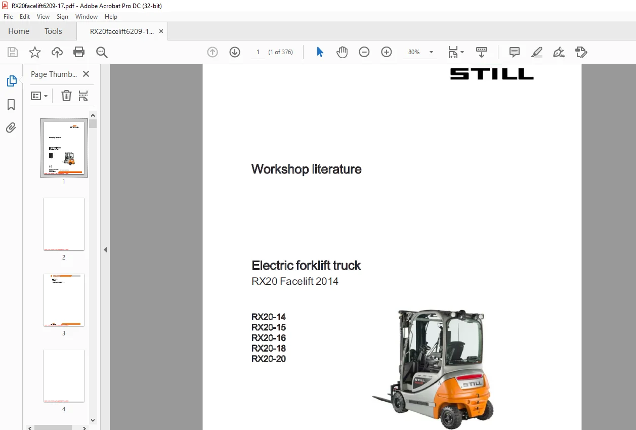
STILL STED Electric forklift truck RX20 Facelift 2014 RX20-14 RX20-15 RX20-16 RX20-18 RX20-20 Workshop Manual – PDF DOWNLOAD
$28.95
STILL STED Electric forklift truck RX20 Facelift 2014 RX20-14 RX20-15 RX20-16 RX20-18 RX20-20 Workshop Manual – PDF DOWNLOAD
Description
STILL STED Electric forklift truck RX20 Facelift 2014 RX20-14 RX20-15 RX20-16 RX20-18 RX20-20 Workshop Manual – PDF DOWNLOAD
FILE DETAILS:
STILL STED Electric forklift truck RX20 Facelift 2014 RX20-14 RX20-15 RX20-16 RX20-18 RX20-20 Workshop Manual – PDF DOWNLOAD
Language : English
Pages : 376
Downloadable : Yes
File Type : PDF
DESCRIPTION:
STILL STED Electric forklift truck RX20 Facelift 2014 RX20-14 RX20-15 RX20-16 RX20-18 RX20-20 Workshop Manual – PDF DOWNLOAD
Identifying features of the Facelift 2014
Externally, it is difficult to distinguish the RX20 Facelift 2014 from its predecessors. The serial number is one indication. The serial numbers listed in the table are the first trucks of each type. From these serial numbers onwards, the trucks have the series production status of the RX20 Facelift 2014. In addition, there are two other features that can help when it comes to identifying the trucks.
Special features of the Facelift 2014 Improved properties:
IMAGES PREVIEW OF THE MANUAL:
TABLE OF CONTENTS:
STILL STED Electric forklift truck RX20 Facelift 2014 RX20-14 RX20-15 RX20-16 RX20-18 RX20-20 Workshop Manual – PDF DOWNLOAD
Product overview for the RX20 Facelift2014 00- 1
Safetyinformation 00- 4
Safety instructions Electrical system 00- 4
Jackingup the frontofthetruck LL 00- 4
Jackinguptherearofthetruck 00- 6
Securing theforkcarriage 00- 7
01 Service
Maintenance 01-1
Maintenance instructions LLL 01-1
Maintenance — 1000 hours/annually 01- 3
Maintenance – 3000 hours/everytwoyears 01- 5
Tools 01-7
Standardtorques 01-7
Measuring and testingequipment 01- 8
Harnessesandhoists 01- 9
Generaltechnicaldata 11-1
Electricalconnections 11-1
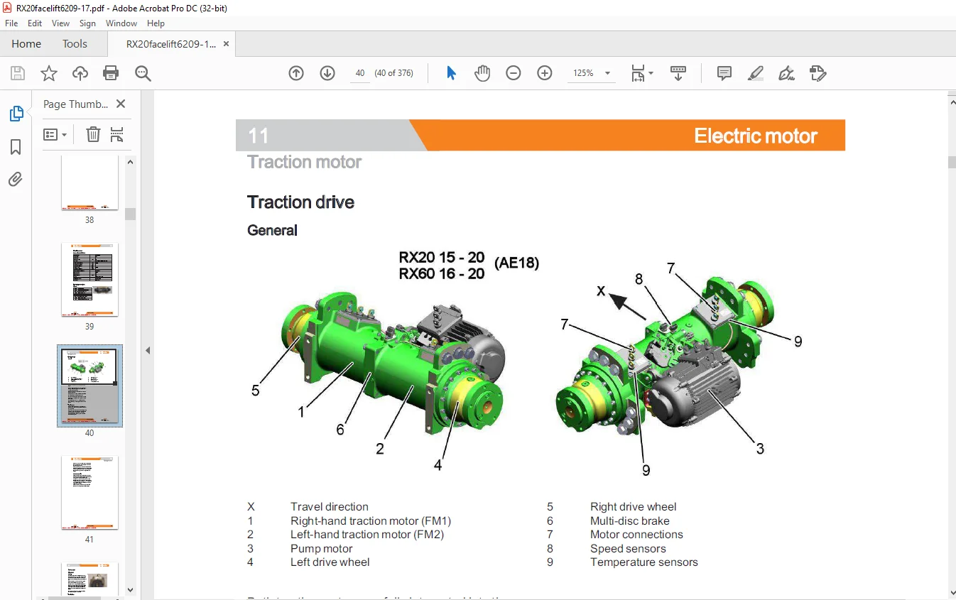
Tractiondrive 11- 2
Pin Sensor 11- 4
Temperature sensor KTY84 11- 6
Generaltechnicaldata 22- 1
AE18-09driveaxle 22- 2
Removing thedrivewheelunit 22- 3
Changing the shaft seal onthe drive wheelunit 22- 4
Refittingthedrivewheelunit 22- 8
Traction motor— Removingtherotor 22- 8
STILL
Table of contents
Traction motor – Installing therotor
Dismantlingthebrake
Assemblingthebrake iL
Filingwithoil
Batterydoor
Counterweight
Overheadguard
Generaltechnicaldata
Steeringsystem LL
Steering—errordetection
Steeringunit
Priorityvalve
Steeringcolumn LLL
Steeringanglesensor oi
Steering angle-dependent handling performance —CSC
CSC-functionaltest
General technical dataFifthwheel
Fifthwheel
Curveswitch
General technical dataSwingaxle
Swingaxle
Swingaxlecurveswitch
Table of contents
Steeringangle 42-32
Tierod 42-33
Axlestub 42-34
Changing the AE18-09 brakecable 49- 1
AE18-09servicebrake 49- 3
Handbrake cablechanger 49- 5
Actuating force ofthehandbrake LL 49- 6
Parking brake switch 1S3 49- 7
Electricparkingbrake 49- 9
Function 49-10
Causeandeffect 49-12
Designand systemdescription 49-14
Maintenance instructions 49-16
Checkingthebrake 49-17
Calibration and functionaltest 49-19
Changing the parking brakecable 49-22
Limitpositionswitch 49-25
Drive unit Installationandremoval 49-27
Central lubrication device Installationandremoval 49-29
Brake Sensor 50- 1
Singlepedal 50- 3
Accelerator—single-pedal 50- 3
Deadmanswitch7S13 50- 6
Dualpedal 50- 7
Accelerator—dual pedal 2nd generation LL 50- 7
Operatingdevices 50-12
Hand lever 50-12
Joystick 4Plus 50-1
Generation2mini-lever
Axle assignment-theminidlever L
Tipswitch
Direction indicatormodule (Fabli)
Display operating unit (ABE 2) Generation2
General technicaldata-48V
Overviewofthecontrollers
Electrical system
Electricalcomponents
Switching on procedure for the electrical system
Software compatibility
PANDProcess i
Parametermanagement
Errorringbuffer
Intermediate circuit
Insulation testing for electrictrucks
Insulation testing on the drive battery
Componentinsulationtesting
Temperature monitoring for the traction motor-48Vv
Temperature monitoring for the traction motor converter
Pump motor temperature monitoring LL
Temperature monitoring for the pump motor converter
Available driving behaviour LL
Revolution-controlled vs torque-regulated
Sprintmode
Blue-Q=1Q
Startingcurrentboost
Table of contents
CANbDus system 60-32
CANbusconnections 60-34
Powercables 60-36
Maintenance guidelines forpowercables 60-37
Repair-Contactelements 60-37
Fusebox (PDU) 60-39
FUSES 60-40
Contactor 60-41
Vertical lift mast position 60-43
Titanglesensor7B46 LL 60-44
Tiltangle sensor parameters 60-46
Installation of the vertical lift mast position 60-47
Load measurement LL 60-50
Load measurement pressure SeNSOr LL 60-52
7A21converterPCB 60-54
OptionBoard 60-55
CAN-Power-Port (CPP) 60-57
CPP 1/ CPP 3 60-57
CPP 2B 60-59
CPP battery carrier (CPPS) 60-60
Relay-Power-Port 60-61
Main Control Unit(MCU 2) 64- 1
Main Control Unit (MCU) Removal and installation 64- 2
Supply Unit (SU 2) 64- 4
Supply Unit (SU) Removal and installation 64- 5
INVER EIS 64- 8
SAC1 1converter-48YV 64- 8
Removing and installingthe converter 64-10
Battery 69- 1
Approved battery male connectors in the Facelift2014 69- 3
Batteryplug 69- 4
Maintenance guidelines forapplianceplugs 69- 5
Repair – Battery male connectorcontacts L 69- 7
Working withreducersleeves 69- 9
2014 dischargeindicator LL 69-10
Generaltechnicaldata 70- 1
Depressurisingthe hydraulics LL 70- 2
Operating speeds forlifting 70- 4
Operating speeds forlowering 70- 4
Tilting operatingspeeds 70- 5
Forwardtiltsafetytest 70- 7
Loweringsafetytest 70- 7
Safety checks ofhoseassembly i 70- 8
Basichydraulics 70- 9
Steering hydraulics 70-10
Working hydraulics 70-11
Hydraulictank 70-12
Intake filter 70-12
Hydraulicoil 70-12
Returnlinefilter 70-14
Breatherfilter 70-15
High-pressurefilter 70-16
Conical nipple fittings (CNF) 70-17
Boltedjoint 70-17
Generaltechnicaldata 71-1
Pumpunit 71- 2
Pumpmotorremoval 71- 5
Pumpmotorinstallation 7-7
Hydraulicpump 71-10
Hydraulic pump Removal and installation 71-11
Tilteylinder 71-15
Masttilt 71-15
Tilt cylinder Removaland installation 71-15
Changing the setof seals (1500-2000kg) 71-16
Auxiliary hydraulics 71-19
Attachments 71-19
Second operating function forattachments 71-20
Clamp locking mechanism with servo hydraulics 71-20
Clamp locking mechanism forhandlevers 71-22
Accumulator 71-24
Accumulator 71-24
Checkingtheaccumulator 71-25
76 Valves
Hand lever 76- 1
Generaltechnicaldata 76- 1
Handlevervalveblock 76- 3
Emergencylowering 76- 4
Hydraulictransmitter 76- 5
Dismantling and installing valve block 76- 7
Directional control valve with blocking function (Buchholz) 76-11
Directional control valve with check valve 2Y46 76-11
Discharge pressure governor (loweringbrake) 76-12
Check valve for hydraulics blocking function 76-12
Servohydraulics 76-14
Generaltechnicaldata 76-14
Servo hydraulics valve block 76-15
Manuallowering 76-16
Directional control valve block 76-17
Directional control valve – method of operation 76-19
STILL
Table of contents
Generaltechnicaldata 81- 1
Mastbearings 81- 2
Hose safety valve of triplexmast 81- 3
Supportroller play (108/117/130) 81- 6
Load chains – Checkingandcleaning 81- 7
Run-outbarrier 81- 8
Workingonliftmasts 81-10
Liftmast—removal 81-11
Liftmast—installation 81-12
Telescopicliftmast (108/117/130) 81-15
Adjusting the load chains Telescopic lit mast (108/117/130) 81-16
NiHoliftmast (108/117/130) 81-18
Adjusting the load chains NiHo lift mast (108/117/130) 81-20
Triple lift mast (108/117/130) 81-22
Removing the supportrollersintheliftmast 81-24
Assembling the lift mast after replacing the supportrollers 81-27
Outer load chains and chainrollers 81-29
Middle load chainand chainroller 81-31
Adjusting the outer load chains Triple lift mast (108/117/130) 81-33
Adjusting the middle load chain Triple lift mast (108/117/130) 81-34
Liftjack oe 81-36
Workingonlifteylinders 81-37
Outercylinder 81-37
Disassembling/assembling the outercylinder 81-40
Centrecylinder 81-42
Disassembling/assembling the middle cylinder 81-44
End position damping of outercylinder LL 81-47
Middle cylinderenddampener 81-48
STILL
Table of contents
Forkecarriage 84- 1
Hand lever from calendarweek 39/2009 X- 1
Servohydraulics X- 3
Questions? Email us: [email protected]
https://vimeo.com/854595348?share=copy
PLEASE NOTE:
- This is the same manual used by the DEALERSHIPS to SERVICE your vehicle.
- The manual can be all yours – Once payment is complete, you will be taken to the download page from where you can download the manual. All in 2-5 minutes time!!
- Need any other service / repair / parts manual, please feel free to contact us at heydownloadss @gmail.com . We may surprise you with a nice offer
S.M