Trusted Business
Verified & Licensed
Virus Free Files
100% Safe Downloads
Secure Payment
SSL Protected
Instant Delivery
Available Immediately
Still RX50-10 to RX50-16 Electric Forklift Service Manual PDF
$26.95
Still STED Electric forklift truck RX50-10 RX50-13 RX50-15 RX50-16 Workshop Manual – PDF DOWNLOAD
Instant PDF Download
Available immediately
Save to Your Device
Download & keep forever
Antivirus Scanned
100% virus-free
Trusted Worldwide
175,000+ customers
Description
Still STED Electric forklift truck RX50-10 RX50-13 RX50-15 RX50-16 Workshop Manual – PDF DOWNLOAD
FILE DETAILS:
Still STED Electric forklift truck RX50-10 RX50-13 RX50-15 RX50-16 Workshop Manual – PDF DOWNLOAD
Language : English
Pages : 274
Downloadable : Yes
File Type : PDF
IMAGES PREVIEW OF THE MANUAL:
TABLE OF CONTENTS:
Still STED Electric forklift truck RX50-10 RX50-13 RX50-15 RX50-16 Workshop Manual – PDF DOWNLOAD
Table of contents
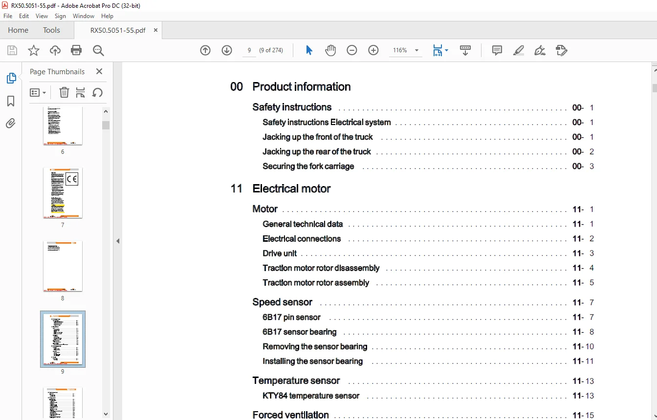
00 Product information
Safetyinstructions 00- 1
Safety instructions Electrical system 00- 1
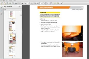
Jackingupthefrontofthetruck 00- 1
Jackinguptherearofthetruck iL 00- 2
Securing theforkcarriage 00- 3
Safety instructions Electrical system 00- 1
Jackingupthefrontofthetruck 00- 1
Jackinguptherearofthetruck iL 00- 2
Securing theforkcarriage 00- 3
11 Electrical motor
Motor 11-1
Generaltechnicaldata 11-1
Electricalconnections LLL 11- 2
Driveunit 11- 3
Traction motorrotordisassembly iL 11- 4
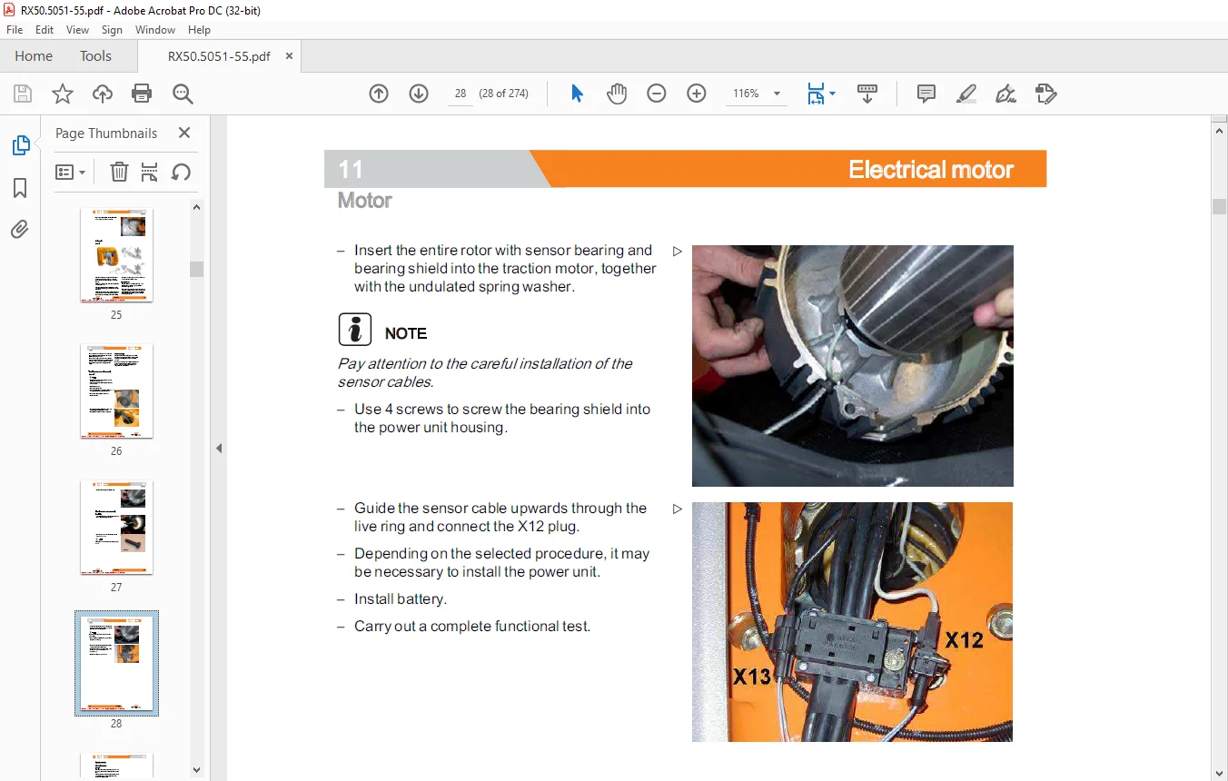
Traction motorrotorassembly i 11- 5
Generaltechnicaldata 11-1
Electricalconnections LLL 11- 2
Driveunit 11- 3
Traction motorrotordisassembly iL 11- 4
Traction motorrotorassembly i 11- 5
Speed Sensor 11-7
BB17 PINSeNSOT oe 11- 7
6B17sensorbearing 11- 8
Removingthesensorbearing 11-10
Installingthe sensorbearing 11-11
BB17 PINSeNSOT oe 11- 7
6B17sensorbearing 11- 8
Removingthesensorbearing 11-10
Installingthe sensorbearing 11-11
Temperature sensor 11-13
KTY84 temperature sensor 11-13
KTY84 temperature sensor 11-13
Forced ventilation i 11-15
Forced ventilation at the pump motor Heavy dustguard 11-15
Forced ventilation at the pump motor Heavy dustguard 11-15
22 Mechanical drive axle
Wheeldrive 22- 1
Wheelhubremoval 22- 1
Installingthewheelhub 22- 2
Wheelhubremoval 22- 1
Installingthewheelhub 22- 2
Powerunit 22- 4
Generaltechnicaldata 22- 4
POWEr Unt 22- 5
Power unitdisassembly 22- 5
Power unitinstallation 22- 7
Generaltechnicaldata 22- 4
POWEr Unt 22- 5
Power unitdisassembly 22- 5
Power unitinstallation 22- 7
31 Chassis
Counterweight 31- 1
Counterweight 31-1
Driversseat 34-1
seatcontactswitch LL 34- 1
Seatbeltlockswitch 34-1
42 Steering system
Hydraulicsteering 42-1
Generaltechnicaldata 42- 1
steering system LLL 42- 2
Steering—errordetection LL 42- 3
Steeringmotor 42- 3
steeringmotorremoval 42- 4
Steering motorinstallation 42- 5
Sprocketwithtriggerwheel 42- 6
Steeringunit 42- 8
diaphragm pressureswitch 42- 9
Priorityvalve 42-10
Steering-angle-dependentperformance-CSC 42-11
CSC—functionaltest 42-12
3B28 steering Zero Sensor 42-13
Steering angle sensorwithsensordisc 42-14
Steeringangle Sensor LLL 42-15
Steering wheel with steeringcolumn 42-17
steeringecolumn LLL 42-17
46 Wheels and tires
Completewheelassembly 46- 1
Generaltechnicaldata 46- 1
Superelastictyres LL 46- 1
Wheelbearing 46-
Generaltechnicaldata 46- 3
Wheelbearing—wheelhub 46-
49 Brake system
Hydraulicservicebrake lL 49- 1
Generaltechnicaldata 49- 1
Replacingthebrakeshoes 49- 1
Checking theservicebrake 49- 4
Wheelbrake cylinder 49- 5
Mainbrakecylinder 49- 6
Brakesensor1B2 LL 49- 7
Brake fluid switch 49- 8
Parkingbrake 49- 9
Adjustingthe parkingbrake 49- 9
parkingbrakeswitch 49-11
Mainbrakecylinder 49- 6
Brakesensor1B2 LL 49- 7
Brake fluid switch 49- 8
Parkingbrake 49- 9
Adjustingthe parkingbrake 49- 9
parkingbrakeswitch 49-11
50 Operational controls
Singlepedal 50- 1
Single-pedal accelerator LL 50- 1
Twin-pedal 50- 5
Two-pedalaccelerator 50- 5
Operationalcontrols 50- 8
Handlever 50- 8
Joystick LL 50- 9
Joystickoperation LLL 50-11
Fingertip 50-12
Axleassignment LL 50-14
Depressurisingthe hydraulics 50-17
SWitCh 50-18
emergencyisolatorswitch 50-18
Emergency off switch inthe joystick 50-18
Keyswitch 50-19
56 Indicator elements
operatorcontrolpanel 56- 1
keypad 56- 1
MINICONSOIE 56- 3
keypad 56- 1
MINICONSOIE 56- 3
Display 56- 7
Display and operating element – control processor 56- 7
Programmingmode 56- 9
Password level 1 56-11
Password level2 56-15
Display and operating element – control processor 56- 7
Programmingmode 56- 9
Password level 1 56-11
Password level2 56-15
General 60- 1
Generaltechnicaldata 60- 1
Devicecodeandreadoptions 60- 2
Overview of electricalcomponents 60- 3
Electrical system 60- 4
Switching on procedure for the electricalsystem 60- 5
Traction motor temperature monitoring LL 60- 8
Pump motor temperature monitoring LL 60-10
Software compatibility 60-11
Parametermanagement 60-13
Intermediate circuit 60-14
Insulation testing forelectrictrucks 60-15
Componentinsulationtesting 60-17
WINING 60-20
CANbusconnections 60-20
CANbusconnections 60-20
Electricalinstallation L 60-21
Controlunit (Vo) 60-21
Fuses 60-22
contactor LL 60-23
Controlunit (Vo) 60-21
Fuses 60-22
contactor LL 60-23
Warningsystem 60-24
NON 60-24
NON 60-24
Additional electrical installations 60-25
Rear distributor plate (add-on) 60-25
Frontdistributorplate 60-26
Relayboard 60-27
Rear distributor plate (add-on) 60-25
Frontdistributorplate 60-26
Relayboard 60-27
64 Electronic controls
Traction and working hydraulicscontrol 64- 1
controlcomputer LL 64- 1
Removing and installing the control processor 64- 2
pumpregulator LL 64- 4
Removing and installingthe pump actuator 64- 6
controlcomputer LL 64- 1
Removing and installing the control processor 64- 2
pumpregulator LL 64- 4
Removing and installingthe pump actuator 64- 6
Converter 64- 9
CONVERT 64- 9
Generation 3 converter 64-10
Generation5driveconverter 64-11
CONVERT 64- 9
Generation 3 converter 64-10
Generation5driveconverter 64-11
Removing andinstallingthe converter 64-13
Hydrauliccontroller 64-16
Hydrauliccontrolunit 64-16
Hydrauliccontroller 64-16
Hydrauliccontrolunit 64-16
69 Batteries and accessories
Tractionbattery 69- 1
battery 69- 1
Batteryconnector 69- 3
battery discharge indicator 69- 4
roller platform 69- 6
battery 69- 1
Batteryconnector 69- 3
battery discharge indicator 69- 4
roller platform 69- 6
70 Hydraulics
General 70- 1
Generaltechnicaldata 70- 1
Operating speeds forlifting 70- 2
Operatingspeedstilt 70- 2
Operating speeds forlowering 70- 3
Forwardftiltsafetytest 70- 4
Loweringsafetytest 70- 4
Safety checks ofhoseassembly 70- 5
Generaltechnicaldata 70- 1
Operating speeds forlifting 70- 2
Operatingspeedstilt 70- 2
Operating speeds forlowering 70- 3
Forwardftiltsafetytest 70- 4
Loweringsafetytest 70- 4
Safety checks ofhoseassembly 70- 5
Base hydraulics 70- 6
Hydraulicinstallation 70- 6
hydraulicoiltank 70- 7
Hydraulicoil 70- 8
Intake filter 70- 9
breatherfilter 70-10
High-pressurefilter 70-11
Conical nipple fittings (CNF) 70-12
Boltedjoint 70-12
Hydraulicinstallation 70- 6
hydraulicoiltank 70- 7
Hydraulicoil 70- 8
Intake filter 70- 9
breatherfilter 70-10
High-pressurefilter 70-11
Conical nipple fittings (CNF) 70-12
Boltedjoint 70-12
71 Working hydraulics
Pumpassembly 71-1
Generaltechnicaldata 71-1
Pumpunit 71- 2
electricalconnections LL 71-3
Pump motor-speed sensor 71-3
Temperature sensorpumpmotor 71- 4
motorbrushmonitor 71- 6
Generaltechnicaldata 71-1
Pumpunit 71- 2
electricalconnections LL 71-3
Pump motor-speed sensor 71-3
Temperature sensorpumpmotor 71- 4
motorbrushmonitor 71- 6
brushes
Pumpmotorremoval
Pump motorinstallation
hydraulicpump
Pumpmotorremoval
Pump motorinstallation
hydraulicpump
Hydraulic pump Removal and installation
Tilteylinder
Masttilt
Tilt cylinder Removal and installation
Changingthesetofseals
Masttilt
Tilt cylinder Removal and installation
Changingthesetofseals
Connectionscrewjoints
Additional hydraulics
Attachments
Clamp locking mechanism forhandlevers
Attachments
Clamp locking mechanism forhandlevers
Hoselineonmast
76 Valves
Handlever i
Generaltechnicaldata
Handlevervalveblock
Removing and installing the valve block
Directional control valve -arrangement
Directional control valve – function
Hydraulicsensor
pressureregulator LL
Generaltechnicaldata
Handlevervalveblock
Removing and installing the valve block
Directional control valve -arrangement
Directional control valve – function
Hydraulicsensor
pressureregulator LL
Servohydraulics
Generaltechnicaldata
Servo hydraulics valveblock
Manuallowering
Generaltechnicaldata
Servo hydraulics valveblock
Manuallowering
Directional control valve block
81 Mast
Mast
Generaltechnicaldata
Telescopicmast
NiHoliftmast
friplexmast
Mastremoval LL
Generaltechnicaldata
Telescopicmast
NiHoliftmast
friplexmast
Mastremoval LL
Mastinstallation
Load chains Checking, cleaning 81- 8
Adjusting the load chains Telescopicmast 81- 9
Adjusting the load chains NiHo liftmast 81-11
OuterloadchainTriplemast 81-13
Middleload chain Triplemast 81-15
End positiondamping 81-18
End position damping ofoutercylinder 81-18
Middle cylinderenddampener 81-19
Hosesafetyvalve 81-20
Hose safety valve of triplexmast 81-20
Shock valve installation positions 81-20
Lifteylinder 81-22
Liftjack 81-22
Centrecylinder 81-22
Outercylinder 81-23
Rollers /supportingrollers 81-26
Removing and installing the supportrollers 81-26
84 Load carrier
Forkcarriage 84- 1
Forkecarriage 84- 1
Roller 84- 2
Annex
X Circuit diagrams
Hydraulics X- 1
Handlever X- 1
Servohydraulics X- 3
Customer Support: [email protected]
https://vimeo.com/857042097?share=copy
PLEASE NOTE:
- This is the same manual used by the dealers to diagnose and troubleshoot your vehicle
- You will be directed to the download page as soon as the purchase is completed. The whole payment and downloading process will take anywhere between 2-5 minutes
- Need any other service / repair / parts manual, please feel free to contact [email protected] . We still have 50,000 manuals unlisted
S.M