STILL STED Electric forklift truck RX60-25 – 35, RX60-40 – 50 Workshop Manual – PDF DOWNLOAD
$29.95
STILL STED Electric forklift truck RX60-25 – 35 RX60-40 – 50 Workshop Manual – PDF DOWNLOAD
Description
STILL STED Electric forklift truck RX60-25 – 35, RX60-40 – 50 Workshop Manual – PDF DOWNLOAD
FILE DETAILS:
STILL STED Electric forklift truck RX60-25 – 35, RX60-40 – 50 Workshop Manual – PDF DOWNLOAD
Language : English
Pages : 472
Downloadable : Yes
File Type : PDF
DESCRIPTION:
STILL STED Electric forklift truck RX60-25 – 35, RX60-40 – 50 Workshop Manual – PDF DOWNLOAD
Information about the documentation
- This workshop manual contains all the information required to assist a competent person with all work, repairs and maintenance on this truck.
- For the purposes of clarity and completeness, some components have been deliberately excluded from this workshop manual and described in their own speci?c documentation.
- Changes may be made at short notice and at any time, and are communicated via service information documents. The documentation comprises operating instructions, additional workshop manuals, special documentation and circuit diagrams.
Special features of this series
The series described belongs to the RX family.
A few units with a high proportion of common
parts make up many different trucks of different
versions.
? Ergonomic driver’s workplace
Generation 2 mini-lever
Generation 2 display operating unit
Electric parking brake
? Blue-Q
Characteristic curve optimisation of the drive The following can be parameterised: switching off auxiliary consumers and enabling the consumption display
? Load measurement
? Mast vertical position
? Hydraulics blocking function in accordance
with EN ISO 3691-1
? Container overhead guard
The container roof with its reduced overall height can be added as a variant to all truck types. However, the truck’s actual container compatibility depends on the height of the chassis and must be checked separately. See operating instructions, chapter 7 “Technical data”.
IMAGES PREVIEW OF THE MANUAL:
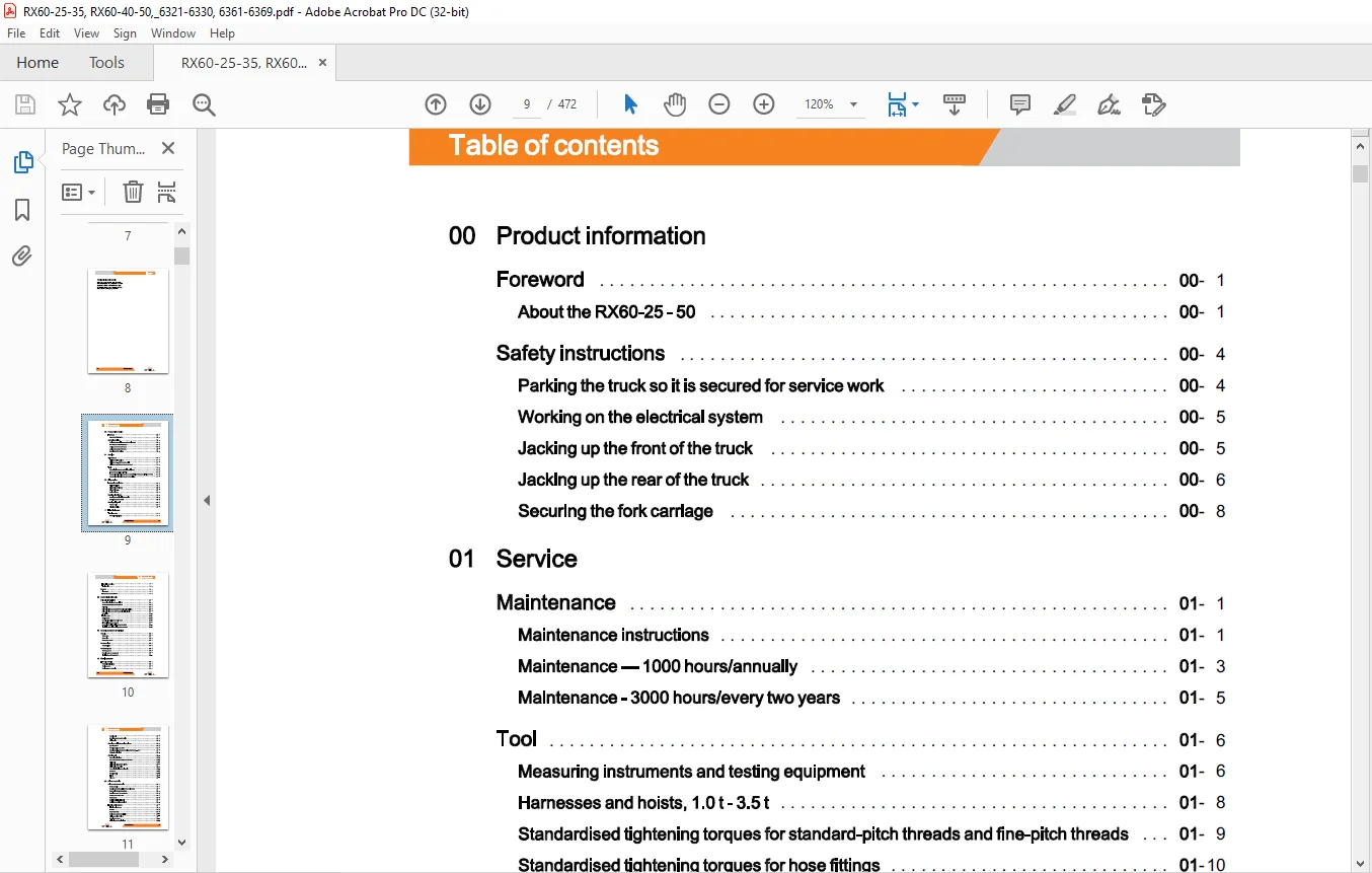
TABLE OF CONTENTS:
STILL STED Electric forklift truck RX60-25 – 35 RX60-40 – 50 Workshop Manual – PDF DOWNLOAD
00 Product information
Foreword 00
About the RX60-25 – 50 00
Safety instructions 00
Parking the truck so it is secured for service work 00
Working on the electrical system 00
Jacking up the front of the truck 00
Jacking up the rear of the truck 00
Securing the fork carriage 00
01 Service
Maintenance 01
Maintenance instructions 01
Maintenance – 1000 hours/annually 01
Maintenance – 3000 hours/every two years 01
Tool 01
Measuring instruments and testing equipment 01
Harnesses and hoists, 1.0 t- 3.5 t 01
Standardised tightening torques for standard-pitch threads and fine-pitch threads 01
Standardised tightening torques for hose fittings 01
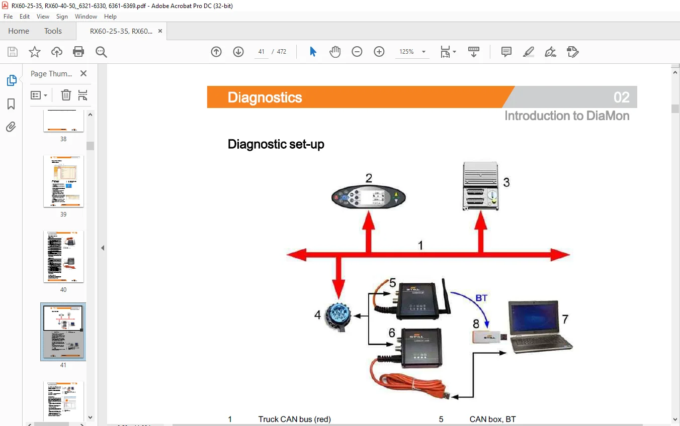
02 Diagnostics
Introduction to DiaMon 02
STEDS-Navigator 02
Diagnostics service box 02
Diagnostic set-up 02
Starting DiaMon 02
Working with DiaMon 02
Reading out and clearing the error list 02
Reading out access codes 02
Working using ABE 02
Read error list 02
Clearing error lists 02
11 Electrical motor
Traction motor 11
General technical data 11
VIII 171861 EN – 10/2017
Table of contents
Electrical connections 11
Traction drive 11
Sensors 11
Pin sensor 11
Temperature sensor KTY84 11
22 Mechanical drive axle
Drive axle EC35-EC50 22
General technical data Carraro EC 35 22
General technical data Carraro EC 50 22
Drive axle 22
Drive axle without pump motor Removal and installation 22
Drive axle with pump motor Removal and installation 22
Wheel drive 22
Traction motor 22
Service brake 22
Removing/installing the service brake 22
Differential gearbox and brake 22
Removal of the differential gearbox and brake 22
Installation of the differential gearbox and brake 22
30 Chassis, bodywork and fittings
Chassis 30
Battery door 30
Battery lock 30
Battery door sensor 30
Counterweight 30
Counterweight 30
Overhead guard 30
Overhead guard 30
Removing the overhead guard 30
Installing the overhead guard 30
42 Steering system
Hydraulic steering 42
General technical data 42
Steering system 42
Steering – error detection 42
171861 EN – 10/2017 IX
Table of contents
Steering unit 42
6S3 diaphragm pressure switch 42
Priority valve 42
Steering wheel and steering column 42
Steering column 42
Steering angle sensor 3B01 42
Steering angle-dependent handling performance – CSC 42
CSC – functional test 42
Steering axle 42
General technical data 42
General technical data – Type carrier 6330 42
Swing axle 42
Swing axle, reinforced for LP600 42
Swing axle curve switch 42
Removing/installing the swing axle 42
Wheel hub 42
Steering angle 42
Tie rod 42
Axle stub 42
50 Driver’s controls
Drive and brake actuation 50
Brake actuation 50
Changing the brake cable for the service brake 50
Brake cable change, handbrake 50
Actuating force of the handbrake 50
Parking brake switch 1 S3 50
Brake sensor 50
Accelerator- single-pedal 50
Accelerator pedal, generation 2 50
Electric parking brake 50
Electric parking brake 50
Function 50
Cause and effect 50
Design and system description 50
Maintenance instructions 50
Checking the brake 50
Calibration and functional test 50
X 171861 EN – 10/2017
Table of contents
Changing the parking brake cable 50
Limit position switch 50
Drive unit Installation and removal 50
Central lubrication device Installation and removal 50
Double pedal 50
Accelerator- dual pedal, generation 2 50
Accelerator- dual pedal 1 st generation 50
Driver’s controls 50
Hand lever 50
Joystick 4Plus 50
Axle assignment – Joystick 4Plus 50
Generation 2 mini-lever 50
Generation 2 mini-leverActuation 50
Axle assignment – the mini-lever 50
Tip switch 50
Axle assignment – fingertip switch 50
Joystick 50
Joystick operation 50
Generation 1 mini-lever 50
Axle assignment – Joystick, mini-lever 1 50
Switch 50
Dead man switch 7S13 50
56 Display elements
Operating console 56
Direction indicator module (Fabli) 56
Turn indicator module for the drive direction, generation 2 56
Drive direction turn indicator display 56
Display 56
Display operating unit (ABE 1) Generation 1 56
ABE 1 Installation and removal 56
Display and operating unit, generation 2 (ABE 2) 56
ABE 2 Installation and removal 56
60 Electrics / Electronics
General 60
General technical data 6321 – 6325 60
171861 EN – 10/2017 XI
Table of contents
General technical data 6326 – 6330
Overview of the controllers
Electrical system
Electrical components
Switching on procedure for the electrical system
Software compatibility
PAN process
Parameter management
Error ring buffer
Intermediate circuit
Insulation testing for electric trucks
Insulation testing on the drive battery
Component insulation testing
Temperature monitoring for the traction motor- 80 V
Temperature monitoring for the traction motor converter
Pump motor temperature monitoring
Temperature monitoring for the pump motor converter
Available driving behaviour
Drive mode – driving behaviour Description
Blue-Q=IQ
Wiring
CAN bus system
CAN bus connections
Power cables
Maintenance guidelines for power cables
Repair – Contact elements
Electrical system
Fusebox
Fuses
Contactor
Sensor system
Vertical lift mast position
Tilt angle sensor 7B46
Tilt angle sensor parameters
Installation of the vertical lift mast position
Load measurement
Load measurement pressure sensor
XII 171861 EN – 10/2017
Table of contents
Additional electrical installation 60
7 A21 converter PCB 60
Option Board 60
CAN-Power-Port (CPP) 60
CPP 1/CPP3 60
CPP2B 60
CPP2/CPP4 60
CPP battery carrier (CPP5) 60
Relay-Power-Port 60
64 Electronic controllers
Traction and working hydraulics control 64
Main Control Unit (MCU) 64
MCU with servo hydraulics 64
MCU generation 2 64
Main Control Unit (MCU) Removal and installation 64
Supply Unit (SU) 64
Supply Unit (SU) Removal and installation 64
Inverters 64
Inverters 64
Converter LAC – 80 Volt 64
SAC converter- 80 Volt 64
Inverters Removal and installation 64
69 Batteries and accessories
Traction battery 69
Battery 69
2014 discharge indicator 69
Discharge indicator 69
Battery plug 69
Maintenance guidelines for appliance plugs 69
Repair – Battery male connector contacts 69
Working with reducer sleeves 69
70 Hydraulics
General 70
General technical data 70
Depressurising the hydraulics 70
Lifting operating speeds 70
Table of contents
Lowering operating speeds 70
Tilting operating speeds 70
Safety check 70
Forward tilt safety test 70
Lowering safety test 70
Safety checks of hose assembly 70
Basic hydraulics 70
Basic hydraulics 70
Steering hydraulics 70
Working hydraulics 70
Hydraulic tank 70
Hydraulic oil 70
Return line filter 70
Breather filter 70
Suction filter 70
Intake filter 70
High-pressure filter 70
Conical nipple fittings (CNF) 70
Bolted joint 70
71 Working hydraulics
Pump unit 71
General technical data 71
Pump unit 71
Electrical connections 71
Pump motor without rev sensor 71
Pump motor temperature sensor 71
Pump motor Removal and installation 71
Hydraulic pump 71
Hydraulic pump Removal and installation 71
Tilt cylinder 71
Mast tilt 71
Tilt cylinder Removal and installation 71
Changing the set of seals, 2000-5000 kg 71
Changing the set of seals 5000 kg – LSP 600 71
Auxiliary hydraulics 71
Attachments 71
Table of contents
Second operating function for attachments 71
Clamp locking mechanism with servo hydraulics 71
Clamp locking mechanism for hand levers 71
Accumulator 71
Accumulator 71
Checking the accumulator 71
76 Valves
Hand lever 76
General technical data 76
Hand lever valve block 76
Emergency lowering 76
Hydraulic transmitter 76
Valve block Removal/ installation 76
Directional control valve block 76
Check valve for hydraulics blocking function 76
Servo hydraulics 76
General technical data 76
Servo hydraulics valve block 76
Manual lowering 76
Directional control valve block 76
80 Load lift system
Mast bearings 80
Mast bearings, Carraro for STILL lift mast 80
Carraro EC50 and EC50I mast bearings 80
81 Lift mast – 2500-3500
Lift mast 81
General technical data 81
Hose safety valve of triplex mast 81
Support roller play ( 108/117 /130) 81
Load chains – Checking and cleaning 81
Run-out barrier 81
Working on lift masts 81
Lift mast- removal 81
Lift mast- installation 81
Table of contents
Telescopic lift mast 81
Telescopic lift mast ( 108/117 /130) 81
Adjusting the load chains Telescopic lift mast (108/117 /130) 81
Ni Ho lift mast 81
NiHo lift mast (108/117/130) 81
Adjusting the load chains NiHo lift mast (108/117/130) 81
Triple mast 81
Triple lift mast ( 108/117 /130) 81
Removing the support rollers in the lift mast 81
Assembling the lift mast after replacing the support rollers 81
Outer load chains and chain rollers 81
Middle load chain and chain roller 81
Adjusting the outer load chains Triple lift mast ( 108/117 /130) 81
Adjusting the middle load chain Triple lift mast ( 108/117 /130) 81
Lift cylinders 81
Lift jack 81
Working on lift cylinders 81
Outer cylinder 81
Disassembling/assembling the outer cylinder 81
Centre cylinder 81
Disassembling/assembling the middle cylinder 81
End position damping, type B (bottom) 81
End position damping, type A (top) 81
81 Lift mast – 4000-5000
Lift mast 81
General technical data 81
Hose safety valve of triplex mast 81
Support roller play ( 150) 81
Load chains – Checking and cleaning 81
Working on lift masts 81
Lift mast – Removal 81
Lift mast- Installation 81
Telescopic lift mast 81
Telescopic lift mast (150) 81
Removing the support rollers in the lift mast 81
Assembling the lift mast after replacing the support rollers 81
XVI 171861 EN – 10/2017
Adjusting the load chains Telescopic lift mast ( 150)
Triple mast
Triple mast (150)
Adjusting the outer load chains Triple mast ( 150)
Load chain adjustment midpoint Triple mast ( 150)
Lift cylinders
Lift jack
Working on lift cylinders
Outer cylinder
84 Load support
Fork carriage – 2500-3500
Fork carriage
Fork carriage – 4000-5000
Fork carriage – Removing in an upwards direction
Fork carriage – Removing in a downwards direction
Annex
X Diagrams
Hydraulics
Hydraulic circuit diagram Multi-levers
Hydraulic circuit diagram Servo hydraulics
Customer Support: [email protected]
https://vimeo.com/855607544?share=copy
PLEASE NOTE:
- This is the same manual used by the dealers to diagnose and troubleshoot your vehicle
- You will be directed to the download page as soon as the purchase is completed. The whole payment and downloading process will take anywhere between 2-5 minutes
- Need any other service / repair / parts manual, please feel free to contact [email protected] . We still have 50,000 manuals unlisted
S.M