Still STED Electric forklift truck RX60-25-35, RX60-40-50 Workshop manual – PDF DOWNLOAD
$28.95
Still STED Electric forklift truck RX60-25-35, RX60-40-50 Workshop manual – PDF DOWNLOAD
Electric forklift truck RX60-25-35, RX60-40-50
RX60-25 RX60-30
RX60-35
RX60-40
RX60-45
RX60-50
Description
Still STED Electric forklift truck RX60-25-35, RX60-40-50 Workshop manual – PDF DOWNLOAD
FILE DETAILS:
Still STED Electric forklift truck RX60-25-35, RX60-40-50 Workshop manual – PDF DOWNLOAD
Language : English
Pages : 460
Downloadable : Yes
File Type : PDF
DESCRIPTION:
Still STED Electric forklift truck RX60-25-35, RX60-40-50 Workshop manual – PDF DOWNLOAD
Electric forklift truck RX60-25-35, RX60-40-50
RX60-25 RX60-30
RX60-35
RX60-40
RX60-45
RX60-50
Special features of this series
The series described belongs to the RX family. A few units with a high proportion of common parts make up many different trucks of different versions.
Still STED Electric forklift truck RX60-25-35 RX60-40-50 Workshop manual – PDF DOWNLOAD
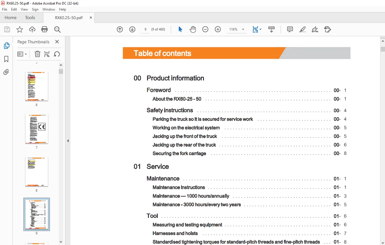
Aboutthe RXB0-25-50 00- 1
Safetyinstructions 00- 4
Parking the truck so itis secured for servicework 00- 4
Working onthe electrical system i 00- 5
Jacking up the frontofthetruck LL 00- 5
Jackinguptherearofthetruck iL 00- 6
Securing theforkcarriage 00- 8
01 Service
Maintenance 01-1
Maintenance instructions LL 01-1
Maintenance — 1000 hours/annually 01- 3
Maintenance – 3000 hours/everytwoyears 01- 5
Tool 01- 6
Measuring and testingequipment 01- 6
Harnessesand hoists 01-7
Standardised tightening torques for standard-pitch threads and fine-pitch threads 01- 8
Standardised tightening torques for hose fittings 01- 8
STEDS-Navigator 02- 1
CANboxdiagnostics 02- 2
Diagnosticset-up 02- 3
StartingDiaMon 02- 4
Reading outand clearingtheerrorlist 02- 5
Readingoutaccesscodes LL 02- 6
Readerrorlist 02- 7
Clearingerrorlists 02- 9
Tractiondrive 11- 2
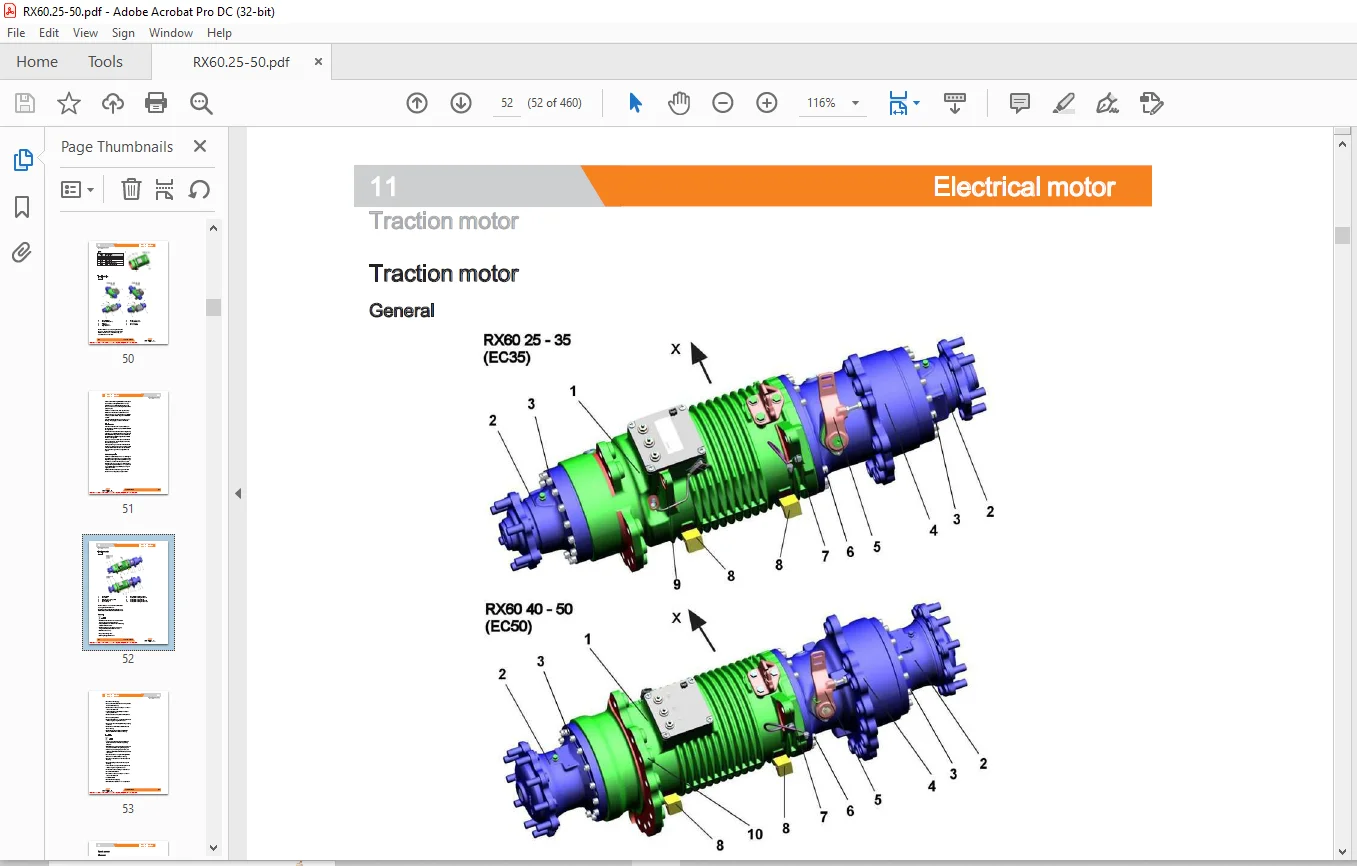
Traction motor 11- 4
Speed sensor 11- 6
Pin Sensor 11- 6
Temperature SEeNSOr i 11- 8
Temperature sensor KTY84 11- 8
22 Mechanical drive axle
Driveaxle EC35-EC50 22- 1
General technicaldataCarraroEC35 22- 1
General technical data CarraroEC50 22- 3
Drive axle 22- 5
Drive axle without pump motor Removal and installation 22- 6
Drive axle with pump motor Removal and installation 22- 9
Wheeldrive 22-12
Differential gearboxandbrake i 22-16
Removal of the differential gearboxandbrake 22-18
Installation of the differential gearboxandbrake 22-21
31 Chassis
Chassis 31- 1
Batterydoor 31-1
Battery lock 31- 2
Batterydoorsensor 31- 4
Counterweight 31- 5
Counterweight 31-5
34 Driver’s compartment
Overheadguard 34-1
Overhead guard 34- 1
Removing the overheadguard i 34-
Installingthe overhead guard 34-
42 Steering system
Hydraulicsteering iL 42-1
Generaltechnicaldata 42- 1
Steering system 42-
Steering unit 42- 5
6S3 diaphragm pressureswitch 42- 7
Priority valve 42-10
Steering wheel and steeringcolumn 42-12
Steeringcolumn 42-12
Steeringanglesensor3B01 LL 42-14
Steering angle-dependent handling performance —CSC 42-16
CSC —functionaltest 42-17
Steeringaxle 42-21
Generaltechnicaldata 42-21
General technical data-Typecarrier6330 42-21
Swingaxle 42-23
Swing axle, reinforced forLP600 La 42-24
Swingaxlecurveswitch 42-24
Removing/installingthe swingaxle 42-25
Wheelhub 42-28
Steeringangle 42-30
Tierod 42-31
Axlestub 42-32
Changing the brake cable Servicebrake 49- 1
Servicebrake 49- 2
Removing/installingthe servicebrake 49- 3
Brake cable change, handbrake 49- 5
Actuating force ofthe handbrake 49- 7
Parking brake switch 183 49- 8
Electricparkingbrake 49-10
Function 49-11
Causeandeffect 49-13
Design and systemdescription 49-15
Maintenance instructions LL 49-17
Checkingthebrake 49-18
Changing the parkingbrakecable
Limitpositionswitch oo
Drive unit Installationandremoval
Brakesensor
Accelerator—single-pedal iL
Dead manswitch7S13
Accelerator—dual pedal 2nd generation
Accelerator —dual pedal 1stgeneration
Handlever
Joystick4Plus
Axle assignment -Joystick4Plus LL
Joystick
Joystickoperation
Generation Tmini-lever
Generation2mini-lever
Generation 2 mini-leverActuation
Tipswitch
Direction indicatormodule (Fabli)
Display operating unit (ABE 1) Generation1
ABE 1 Installationandremoval
Display and operating unit, generation2(ABE2)
General technical data 6321-6325 60- 1
General technical data 8326-6330 0 60- 3
Overviewofthecontrollers 60- 4
Electrical system 60- 5
Electricalcomponents 60- 5
Switching on procedure for the electricalsystem 60- 7
Software compatibility 60-12
PAN DrOCESS «oo 60-13
Parametermanagement LLL 60-14
Errorring buffer 60-15
Intermediate circuit 60-16
Insulation testing forelectrictrucks 60-17
Insulation testingonthedrivebattery 60-19
Componentinsulationtesting 60-20
Temperature monitoring for the traction motor-80V 60-22
Temperature monitoring for the traction motorconverter 60-24
Pump motor temperature monitoring LL 60-25
Temperature monitoring for the pump motorconverter 60-26
Available drivingbehaviour 60-28
Drive mode — driving behaviour Description 60-28
BlUe-Q=1Q 60-30
CANDbus system 60-32
CANDbusconnections 60-34
Powercables LL 60-36
Maintenance guidelines forpowercables 60-37
Repair-Contactelements 60-37
Fusebox 60-39
FUSES 60-39
Contactor 60-40
Vertical liftmast position 60-42
Tiltanglesensor7B46 60-43
Tittangle sensorparameters 60-45
Load measurement
7A21converterPCB
OptionBoard
CAN-Power-Port (CPP)
CPP1/CPP 3
Relay-Power-Port
Main Control Unit(MCU)
MCUwithservohydraulics
MCUgeneration2 i
Main Control Unit (MCU) Removal and installation
SupplyUnit (SU)
Supply Unit (SU) Removal and installation
Inverters
Converter LAC-80Volt
SACconverter—80Volt
2014 dischargeindicator LL
Dischargeindicator
Batteryplug
Maintenance guidelines for applianceplugs
Repair – Battery male connectorcontacts
Working withreducersleeves
Generaltechnicaldata 70- 1
Hydraulicoil 70- 3
Depressurising the hydraulics 70- 4
Litingoperatingspeeds LL 70- 6
Loweringoperatingspeeds LL 70- 7
Tiltingoperatingspeeds 70- 7
Forward tiltsafetytest 70- 9
Lowering safetytest 70- 9
Safety checksofhoseassembly 70-10
Basichydraulics 70-11
Steering hydraulics 70-12
Working hydraulics 70-13
Hydraulictank 70-14
Returnlinefilter 70-14
Breatherfilter 70-16
Suction filter 70-17
Intake filter LL 70-18
High-pressurefilter 70-18
Conical nipple fittings (CNF) 70-19
Boltedjoint 70-19
Generaltechnicaldata 71-1
Pumpunit 71-1
Electricalconnections 71-2
Pump motor withoutrevsensor i 71-3
Pump motortemperature sensor LL 71- 3
Pump motor Removal and installation 71- 5
Hydraulicpump 71- 6
Hydraulic pump Removal and installation 7-7
Masttilt 71-10
Changing the set of seals2200-5000 kg-LSP500 71-12
Changing the set of seals 5000kg-LSP600 71-14
Auxiliary hydraulics 71-17
Attachments 71-17
Second operating function forattachments 71-20
Clamp locking mechanism with servo hydraulics 71-20
Clamp locking mechanism forhandlevers 71-22
Accumulator 71-24
Accumulator LL 71-24
Checkingtheaccumulator 71-25
76 Valves
Handlever 76- 1
Generaltechnicaldata 76- 1
Handlevervalveblock 76- 2
Emergencylowering LL 76- 3
Hydraulic transmitter 76- 4
Valve block Removal /installation 76- 6
Directional control valve block 76- 8
Check valve for hydraulics blocking function 76-10
Servohydraulics 76-11
Generaltechnicaldata 76-11
Servo hydraulics valve block 76-12
Manuallowering 76-13
Directional control valve block 76-14
Generaltechnicaldata 81- 1
Mast bearings, Carrarofor STILL liftmast 81- 2
Hose safety valve of triplexmast 81- 4
Supportroller play (108/117/130) 81- 7
Load chains – Checkingand cleaning 81- 8
Run-outbarrier 81- 9
Workingonliftmasts 81-11
Liftmast—removal 81-12
Liftmast—installation 81-13
Telescopic liftmast (108/117/130) 81-16
Adjusting the load chains Telescopic lit mast (108/117/130) 81-17
NiHolift mast (108/117/130) 81-19
Adjusting the load chains NiHo lift mast (108/117/130) 81-21
Triple lift mast (108/117/130) 81-23
Removing the supportrollersintheliftmast 81-25
Assembling the lift mast after replacing the supportrollers 81-28
Outerload chainsandchainrollers 81-30
Middle load chainand chainroller 81-32
Adjusting the outer load chains Triple lift mast (108/117/130) 81-34
Adjusting the middle load chain Triple lift mast (108/117/130) 81-35
Liftjack 81-37
Workingonlifteylinders 81-38
Outercylinder 81-38
Disassembling/assembling the outercylinder 81-41
Centrecylinder 81-43
Disassembling/assembling the middle cylinder 81-45
End position damping ofoutercylinder 81-48
Middle cylinderenddampener LL 81-49
Generaltechnicaldata 81- 1
Carraro EC50and EC50Imastbearings 81- 1
Hose safety valve of triplexmast 81- 4
Supportrollerplay (150) 81- 7
Load chains – Checkingandcleaning 81- 8
Workingonliftmasts 81-10
Lit mast-Removal 81-11
Lit mast-Installation 81-12
Telescopicliftmast (150) 81-14
Removing the supportrollersintheliftmast 81-15
Adjusting the load chains Telescopiclitmast (150) 81-17
Triplemast 81-18
Triplemast (150) 81-18
Adjusting the outer load chains Triple mast (150) 81-19
Load chain adjustment midpoint Triplemast (150) 81-20
Lifteylinders 81-22
Liftjack oe 81-22
Working onliftcylinders 81-23
Outercylinder 81-24
Annex
Hydraulic circuit diagram Multi-levers lL X- 2
Hydraulic circuit diagram Servo hydraulics X- 4
IMAGES PREVIEW OF THE MANUAL:

Questions? Email us: [email protected]
PLEASE NOTE:
- This is the same manual used by the DEALERSHIPS to SERVICE your vehicle.
- The manual can be all yours – Once payment is complete, you will be taken to the download page from where you can download the manual. All in 2-5 minutes time!!
- Need any other service / repair / parts manual, please feel free to contact us at heydownloadss @gmail.com . We may surprise you with a nice offer
S.M