STILL STED Electric forklift truck RX60-60 RX60-70 RX60-80 Workshop Manual – PDF DOWNLOAD
$28.95
STILL STED Electric forklift truck RX60-60 RX60-70 RX60-80 Workshop Manual – PDF DOWNLOAD
Description
STILL STED Electric forklift truck RX60-60 RX60-70 RX60-80 Workshop Manual – PDF DOWNLOAD
FILE DETAILS:
STILL STED Electric forklift truck RX60-60 RX60-70 RX60-80 Workshop Manual – PDF DOWNLOAD
Language : English
Pages : 320
Downloadable : Yes
File Type : PDF
DESCRIPTION:
STILL STED Electric forklift truck RX60-60 RX60-70 RX60-80 Workshop Manual – PDF DOWNLOAD
Product overview for the RX60 60-80
Longer battery life in particularly severe
conditions thanks to the active battery cooling
system
? New sprint mode with a higher drive power and
lifting speed
Sprint mode is only possible in combination
with the PowerPlusLife battery
? New accelerator pedal from CW 31/2017
has a very high output in comparison with its
electric counterparts.
? A large battery capacity for long periods of use
- Excellent manoeuvrability for negotiating narrow aisles
- Excellent driving and steering characteristics
- A high level of visibility on all sides thanks to a driver’s cab positioned to one side and a high seat position
- Faster and more secure battery replacements can be performed from the side of the truck, a feature ideally suited for multi-shift use
- Generous, more ergonomic driver’s workstation featuring the typical STILL design
- Low operating costs through low energy and service costs
- Permanent temperature monitoring
- Enhanced battery discharge indicator and consumption display
IMAGES PREVIEW OF THE MANUAL:
TABLE OF CONTENTS:
STILL STED Electric forklift truck RX60-60 RX60-70 RX60-80 Workshop Manual – PDF DOWNLOAD
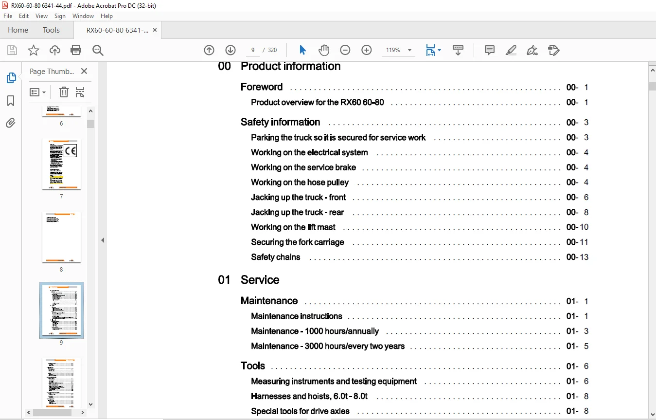
00 Product information
Foreword 00
Product overview for the RX60 60-80 00
Safety information 00
Parking the truck so it is secured for service work 00
Working on the electrical system 00
Working on the service brake 00
Working on the hose pulley 00
Jacking up the truck – front 00
Jacking up the truck – rear 00
Working on the lift mast 00
Securing the fork carriage 00
Safety chains 00
01 Service
Maintenance 01
Maintenance instructions 01
Maintenance – 1000 hours/annually 01
Maintenance – 3000 hours/every two years 01
Tools 01
Measuring instruments and testing equipment 01
Harnesses and hoists, 6 0t- 8 0t 01
Special tools for drive axles 01
Hose pulley special tools 01
Standardised tightening torques for standard-pitch threads and fine-pitch threads 01
Standardised tightening torques for hose fittings 01
02 Diagnostics
Introduction to DiaMon 02
STEDS-Navigator 02
CAN box diagnostics 02
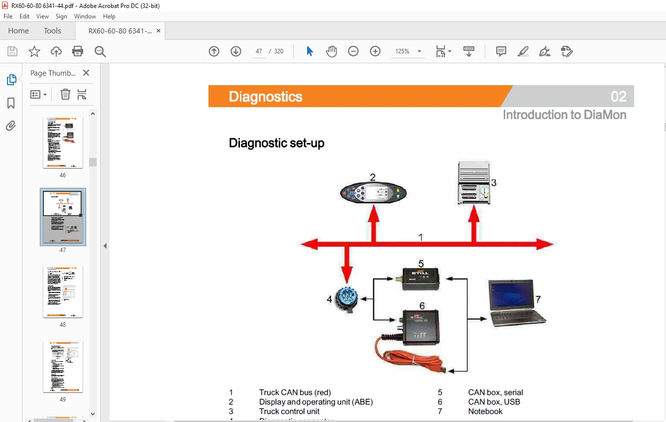
Diagnostic set-up 02
Starting DiaMon 02
Working with DiaMon 02
Reading out and clearing the error list 02
Reading out access codes 02
VIII 56358012001 EN – 02/2017
Table of contents
Working using the ABE 02
Read error list 02
Clearing error lists 02
11 Electric motor
Traction motor 11
General technical data 11
Electrical connections 11
Traction motors 11
Sensors 11
Speed sensor 11
Temperature sensor KTY84 11
22 Mechanical drive axle
Drive axle AE80-02 22
General technical data 22
Drive axle AES0-02 22
Drive wheel unit 22
Removing the drive wheel unit and the multi-disc brake 22
Traction motor – Removing the rotor 22
Traction motor- Installing the rotor 22
Installing the drive wheel unit and the multi-disc brake 22
Replacing the bearing and sealing ring for the traction motor 22
Drive wheel unit – Replacing the sealing ring 22
Checking the oil level 22
Oil change 22
30 Chassis, bodywork and fittings
Chassis 30
Working with gas springs 30
Counterweight 30
Counterweight 30
42 Steering system
Hydraulic steering 42
General technical data 42
Steering system 42
Steering angle sensor 3B01 42
Table of contents
Steering – error detection 42
Steering unit 42
Priority valve 42
Steering axle 42
General technical data 42
Swing axle 42
Steering angle sensor 3B02 42
Wheel hub 42
Steering angle 42
Tie rod 42
Axle stub 42
49 Brake system
Hydraulic operating brake 49
General technical data 49
Spring-operated brake 49
Brake valve 49
Accumulator charging section 49
50 Operating devices
Drive and brake actuation 50
Brake actuation 50
Changing the brake cable 50
Brake sensor 50
Parking brake switch 1 S3 50
Accelerator pedal, generation 2 50
Accelerator- single-pedal 50
Accelerator- dual pedal, generation 2 50
Operating devices 50
Joystick 4Plus 50
Axle assignment – Joystick 4Plus 50
Generation 2 mini-lever 50
Axle assignment – the mini-lever 50
Tip switch 50
Axle assignment – fingertip switch 50
Table of contents
56 Display elements
Operating console 56
Turn indicator module for the drive direction, generation 2 56
Direction indicator module (Fabli) 56
Display 56
Display and operating unit, generation 2 (ABE 2) 56
ABE 2 Installation and removal 56
60 Electrical enclosure
General 60
General technical data 60
Overview of electrical components 60
Overview of the controllers 60
Electrical system 60
Software compatibility 60
PAN process 60
Parameter management 60
Error ring buffer 60
Temperature monitoring for the traction motor – 80 V 60
Temperature monitoring for the traction motor converter 60
Pump motor temperature monitoring 60
Temperature monitoring for the pump motor converter 60
Revolution-controlled vs torque-regulated 60
Blue-Q=IQ 60
Starting current boost 60
Stopping on a slope 60
Electrical checks 60
Intermediate circuit 60
Truck insulation testing 60
Insulation testing on the drive battery 60
Component insulation testing 60
Polarity check 60
Wiring 60
CAN bus system 60
CAN bus connections 60
Power cables 60
Maintenance guidelines for power cables 60
56358012001 EN – 02/2017 XI
Table of contents
Repair – Contact elements 60
Electrical system 60
Contactor stand (PDU) 60
Contactor 60
Frontfuse boxA21 60
Rear fuse box A22 60
Additional electrical installation 60
Option Board 60
CAN-Power-Port (CPP) 60
CPP 1/CPP 3 60
CPP2B 60
Cooling system 60
Cooling system 60
Radiator 60
Axial blower 60
Water pump 60
Coolant 60
64 Electronic controls
Traction controller 64
Main Control Unit (MCU 2) 64
Main Control Unit (MCU) Removal and installation 64
Supply Unit (SU2) A43 64
Removing and installing the Supply Unit (SU) 64
Converter 64
Converter 64
SAC converter – 80 volt 64
Removing and installing converters 64
69 Batteries and accessories
Traction battery 69
Battery 69
2014 discharge indicator 69
Battery male connector 69
Converting the battery male connector to 640 A 69
PowerPluslife battery 69
PowerPlusLife battery 69
XII 56358012001 EN – 02/2017
Table of contents
Battery hood 69
Fans 69
Level sensor 69
Temperature sensors 69
70 Hydraulics
General 70
General technical data 70
Releasing the pressure from the hydraulics 70
Operating speeds for lifting 70
Lowering operating speeds 70
Tilt operating speeds 70
Safety check 70
Forward tilt safety test 70
Lowering safety test 70
Safety checks of hose assembly 70
Basic hydraulics 70
Basic hydraulics 70
Steering hydraulics 70
Working hydraulics 70
Hydraulic tank 70
Changing the hydraulic oil 70
Intake filter 70
Return filter 70
Breather 70
High-pressure filter 70
Conical nipple fittings (CNF) 70
Bolted joint 70
71 Working hydraulics
Pump-motor unit 71
General technical data 71
Pump-motor unit 71
Speed sensor for pump motor 71
Temperature sensor KTY84 71
Hydraulic pump 71
Hydraulic pumps Removal and installation 71
56358012001 EN – 02/2017 XIII
Table of contents
Tilt cylinders 71
Removing/installing the tilt cylinder 71
Changing the set of seals 6000 – 8000 kg 71
Truck auxiliary hydraulics 71
Operating speeds of the attachments 71
Second operating function for attachments 71
Clamp locking mechanism with servo hydraulics 71
Accumulator 71
Accumulator 71
Checking the accumulator 71
Hose pulley 71
Hose pulley 71
Removing/installing the hose pulley 71
Releasing and adjusting the tension of the hose pulley 71
Changing the set of seals in the hose pulley 71
Changing the hose line on the four-way hose reel 71
Changing the seals in the swivel joint 71
76 Valves
Servo hydraulics 76
General technical data 76
Valve block 76
Directional control valve – function 76
80 Load lift system
Mast bearings 80
Mast bearings AE80-01, AE80-02 80
81 Lift mast
Lift mast 81
General technical data 81
Line break safety valve 81
Support roller play ( 195) 81
Load chains – Checking and cleaning 81
Working on lift masts 81
Removing the lift mast 81
Installing the lift mast 81
Telescopic lift mast
Telescopic lift mast ( 195)
Telescopic lift mast (195) load chain adjustment
Triplex lift mast
Triplex lift mast ( 195)
Triplex lift mast ( 195) load chain adjustment
Lift cylinder
Working on lift cylinders
Removing/installing outer cylinders
Removing and installing the centre cylinder
End position damping location
End position damping, type A (top)
End position damping, type B (bottom)
Annex
X Circuit diagrams
Hydraulics
Servo hydraulics
Questions? Email us: [email protected]
https://vimeo.com/854913591?share=copy
PLEASE NOTE:
- This is the same manual used by the DEALERSHIPS to SERVICE your vehicle.
- The manual can be all yours – Once payment is complete, you will be taken to the download page from where you can download the manual. All in 2-5 minutes time!!
- Need any other service / repair / parts manual, please feel free to contact us at heydownloadss @gmail.com . We may surprise you with a nice offer
S.M