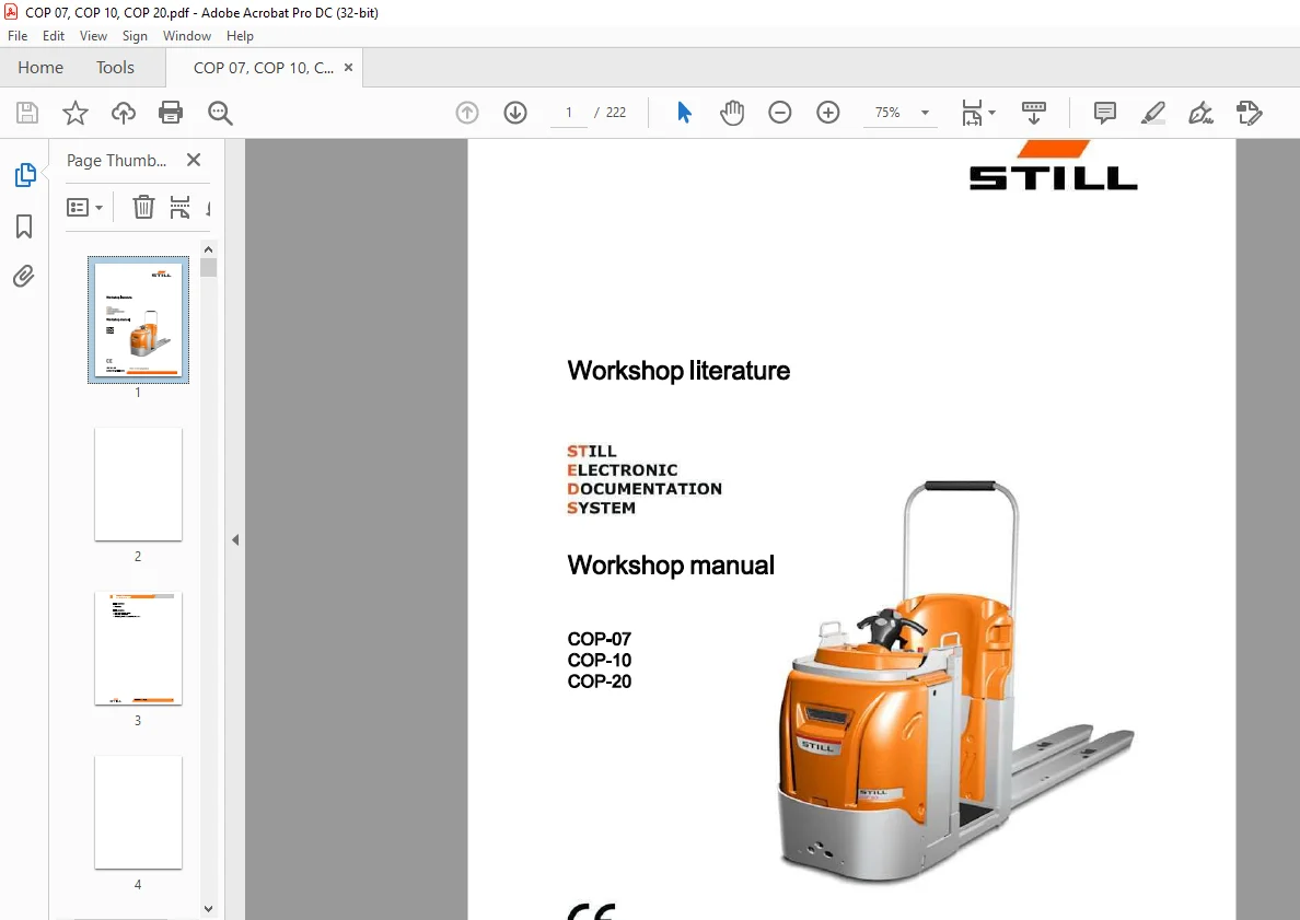
STILL STED forklift COP-07 COP-10 COP-20 workshop Manual – PDF DOWNLOAD
$28.95
STILL STED forklift COP-07 COP-10 COP-20 workshop Manual – PDF DOWNLOAD
Description
STILL STED forklift COP-07 COP-10 COP-20 workshop Manual – PDF DOWNLOAD
FILE DETAILS:
STILL STED forklift COP-07 COP-10 COP-20 workshop Manual – PDF DOWNLOAD
Language : English
Pages : 222
Downloadable : Yes
File Type : PDF
IMAGES PREVIEW OF THE MANUAL:
DESCRIPTION:
STILL STED forklift COP-07 COP-10 COP-20 workshop Manual – PDF DOWNLOAD
Safety precautions
Description of safety symbols
This document gives the danger warnings Each of such danger warnings consists of a graphic symbol, followed by a description of the danger and its consequences, and the description of how it can be avoided. The types of warnings used are described below
Safety Regulations Relative to Operating Materials
Rules for handling and disposing of operating
materials
ENVIRONMENT NOTE
- Improper use and disposal of operating and cleaning materials can cause serious damage to the environment. Always use and handle the operating materials in a suitable manner and follow the manufacturer?s instructions for the product?s use.
- Keep the operating materials only in containers intended for this purpose and in a location that satis?es the requirements. The operating materials may be ?ammable, so avoid contact with hot objects or open ?ames
- When topping up the operating materials, only clean containers should be used. Follow the manufacturer?s safety and disposal instructions regarding the operating and cleaning materials.
- Do not disperse oils or other operating liquids! Any spilt liquid must be immediately collected and neutralised with a binding material (such as an oil binder) and then disposed of in accordance with current regulations.
- Always comply with anti-pollution regulations! Before carrying out work that involves lubrication, ?lter replacement or hydraulic equipment interventions, the area in question must be thoroughly cleaned. The replaced parts must always be disposed of in accordance with the anti-pollution laws.
TABLE OF CONTENTS:
STILL STED forklift COP-07 COP-10 COP-20 workshop Manual – PDF DOWNLOAD
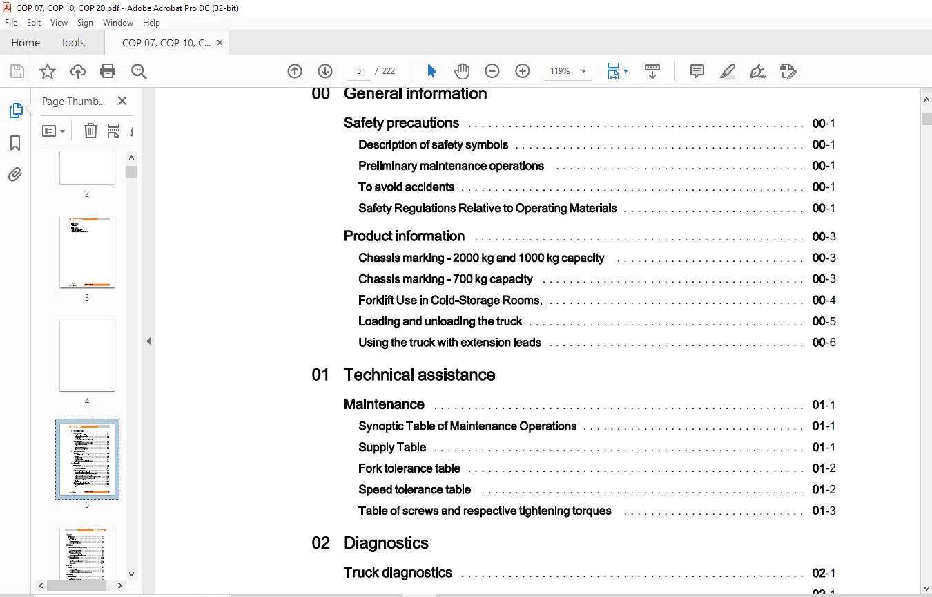
00 General information
Safety precautions 00
Description of safety symbols 00
Preliminary maintenance operations 00
To avoid accidents 00
Safety Regulations Relative to Operating Materials 00
Product information 00
Chassis marking – 2000 kg and 1000 kg capacity 00
Chassis marking – 700 kg capacity 00
Forklift Use in Cold-Storage Rooms 00
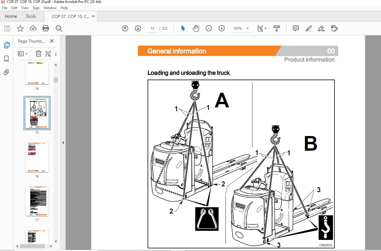
Loading and unloading the truck 00
Using the truck with extension leads 00
01 Technical assistance
Maintenance 01
Synoptic Table of Maintenance Operations 01
Supply Table 01
Fork tolerance table 01
Speed tolerance table 01
Table of screws and respective tightening torques 01
02 Diagnostics
Truck diagnostics 02
02
Software for truck diagnostics 02
Curtis system diagnostics 02
Software for electronic system diagnostics 02
Device monitor (Monitor Menu) – 2000 kg and 1000 kg capacity 02
Device monitor (Monitor Menu) – 700 kg capacity 02
Device parameters (Parameters Menu) – 2000 kg and 1000 kg capacity 02
Device parameters (Parameters Menu) – 700 kg version 02
System fault monitor (Alarms) 02
Alarms list 02
“LES” electrical steering diagnostics 02
“DiaMon – LES” software 02
11 Motor
Traction motor
Drive motor
Technical data plate
Removal of the drive motor
Reassembly of the drive motor
22 Reducer
Disassembly/ Reassembly of the reducer
Disassembly
Removal of the anchorage plate
Extraction of the drive reducer
Assembly of the reducer group
Removing and overhauling the drive reducer
Reducer maintenance
Description of the reducer
Instructions for assembly/ service on the reducer
Adjustment of the bevel gear system
Reducer section
31 Truck
Covers
Internal accessibility
Removal of the upper bonnet
Removal of the gas spring on the battery compartment cover
42 Steering
Table of contents
Steering system 42
L E S electronic control module 42
Inputs-Outputs of the L E S control 42
Removing the steering motor reducer- 2000 kg and 1000 kg capacity 42
Removing the steering motor reducer- 700 kg capacity 42
Removal of the steering potentiometer 42
Reassembling the motor reducer and steering potentiometer – 2000 kg and 1000 kg
capacity 42
Reassembling the motor reducer and steering potentiometer – 700 kg capacity 42
Centering the potentiometer 42
Electrical diagram of the drive wheel position potentiometer 42
Table of contents
L E S interface connection diagram 42
Calibrating the actual value and nominal value potentiometers 42
Calibration of the electrical midpoint 42
Tiller 42
Remove the steering potentiometer on the shaft 42
Removal of shaft head 42
Removal of the shaft potentiometer group 42
Technical information regarding the drive accelerator potentiometer 42
Removal of the horn button 42
Removal of the consent buttons 42
Removing the step plate lifting-lowering buttons 42
Removal of the shaft card 42
Technical information regarding the electronic card for the shaft 42
Removal of the fork lifting-lowering button 42
Shaft head assembly 42
Removal of the shaft head from the forklift 42
Removal of the shaft support housing 42
Reassembly of the shaft support housing 42
46 Wheels and lever systems
Wheels 46
Wheel Wear Check 46
Replacement of the drive wheel 46
Wheel Tightening Check 46
Removal of the stabiliser wheel – 2000 kg and 1000 kg capacity 46
Reassembling the stabiliser wheel – 2000 kg and 1000 kg capacity 46
Checking pivot wheel oil level – 2000 kg and 1000 kg capacity 46
Replacing and topping up pivot wheel oil – 2000 kg and 1000 kg capacity 46
Fork lifting levers – 2000 kg capacity 46
49 Braking system
Braking devices and methods 49
Braking devices and methods 49
Motor braking 49
Electromagnetic brake 49
To check wear and adjustment of the electromagnetic brake 49
Removal of the electromagnetic brake; 49
Table of contents
Service brake (eABS)
Description of service braking (eABS)
Features of the eABS module
eABS module inputs and outputs – 2000 kg and 1000 kg capacity version
eABS module inputs and outputs – 700 kg capacity version
Alarms encoding
List of alarms
Electrical/electronic system: general information 60
Functional diagram for the “Curtis” electronic control system – 2000 kg and 1000 kg
capacity 60
Functional diagram for the “Curtis” electronic control system- 700 kg capacity 60
Main features of the Curtis system 60
Inputs and outputs of the “Curtis” system 60
Temperature control 60
Removal of Curtis three-phase drive system 60
Disassembly of the complete system support 60
Wiring harness 60
Fuses:location, check, replacement 60
Adjusting the dashboard microswitch control screw – 700 kg version 60
Batteries 60
Battery dimensions and weights 60
Removal of the battery status indicator and counter 60
Low battery charge indicator and counter 60
Battery Replacement 60
Stands with rollers for lateral battery extraction (option) 60
Electrolyte Level and Density Check 60
Battery Recharging 60
70 Hydraulic system
Hydraulic diagrams
Solenoid valve unit – 2000 kg capacity
Solenoid valve unit – 1000 kg capacity
Solenoid valve unit – 700 kg capacity – Fixed forks
Solenoid valve unit – 700 kg capacity – Movable forks
Table of contents
71 Hydraulic components
Control unit and accumulator 71
Replacement of the hydraulic control unit 71
Removing the accumulator- 2000 kg and 1000 kg capacity- Movable step plate 71
Hydraulic System Oil Level Check 71
80 Lifting
Fork lifting
Removal of the fork lifting cylinder
Removal of the supply pipe to the fork lifting cylinder
Step plate
Shimming the lateral runner of the mobile platform
Adjust and replace the rubber buffers at the platform stroke end
Cylinders
Drawing of forks lifting cylinder – 2000 kg capacity
Drawing of forks lifting cylinder – 1000 kg capacity
Drawing of fork lift cylinder – 700 kg capacity- Fixed forks
Drawing of fork lift cylinder – 700 kg capacity- Movable forks
Fork lifting cylinder servicing : Disassembly
Fork lifting cylinder servicing : Reassembly
Drawing of step plate lifting cylinder – 2000 kg and 1000 kg capacity
Drawing of step plate lifting cylinder – 700 kg capacity
Removal of platform lifting cylinder
Removal of the platform cylinder supply pipe
Need help? Contact: [email protected]
https://vimeo.com/856148231?share=copy
PLEASE NOTE:
- This is the same manual used by the dealers to diagnose and troubleshoot your vehicle
- You will be directed to the download page as soon as the purchase is completed. The whole payment and downloading process will take anywhere between 2-5 minutes
- Need any other service / repair / parts manual, please feel free to contact [email protected] . We still have 50,000 manuals unlisted
S.M