STILL STED Forklift Diesel LPG forklift trucks R70-40 R70-45 R70-50 workshop Manual – PDF DOWNLOAD
$27.95
STILL STED Forklift Diesel LPG forklift trucks R70-40 R70-45 R70-50 workshop Manual – PDF DOWNLOAD
Description
STILL STED Forklift Diesel LPG forklift trucks R70-40 R70-45 R70-50 workshop Manual – PDF DOWNLOAD
FILE DETAILS:
STILL STED Forklift Diesel LPG forklift trucks R70-40 R70-45 R70-50 workshop Manual – PDF DOWNLOAD
Language : English
Pages : 350
Downloadable : Yes
File Type : PDF
IMAGES PREVIEW OF THE MANUAL:
DESCRIPTION:
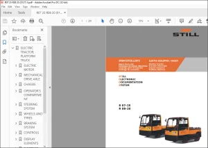
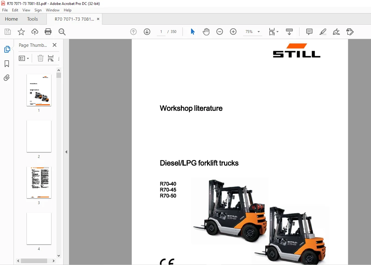
STILL STED Forklift Diesel LPG forklift trucks R70-40 R70-45 R70-50 workshop Manual – PDF DOWNLOAD
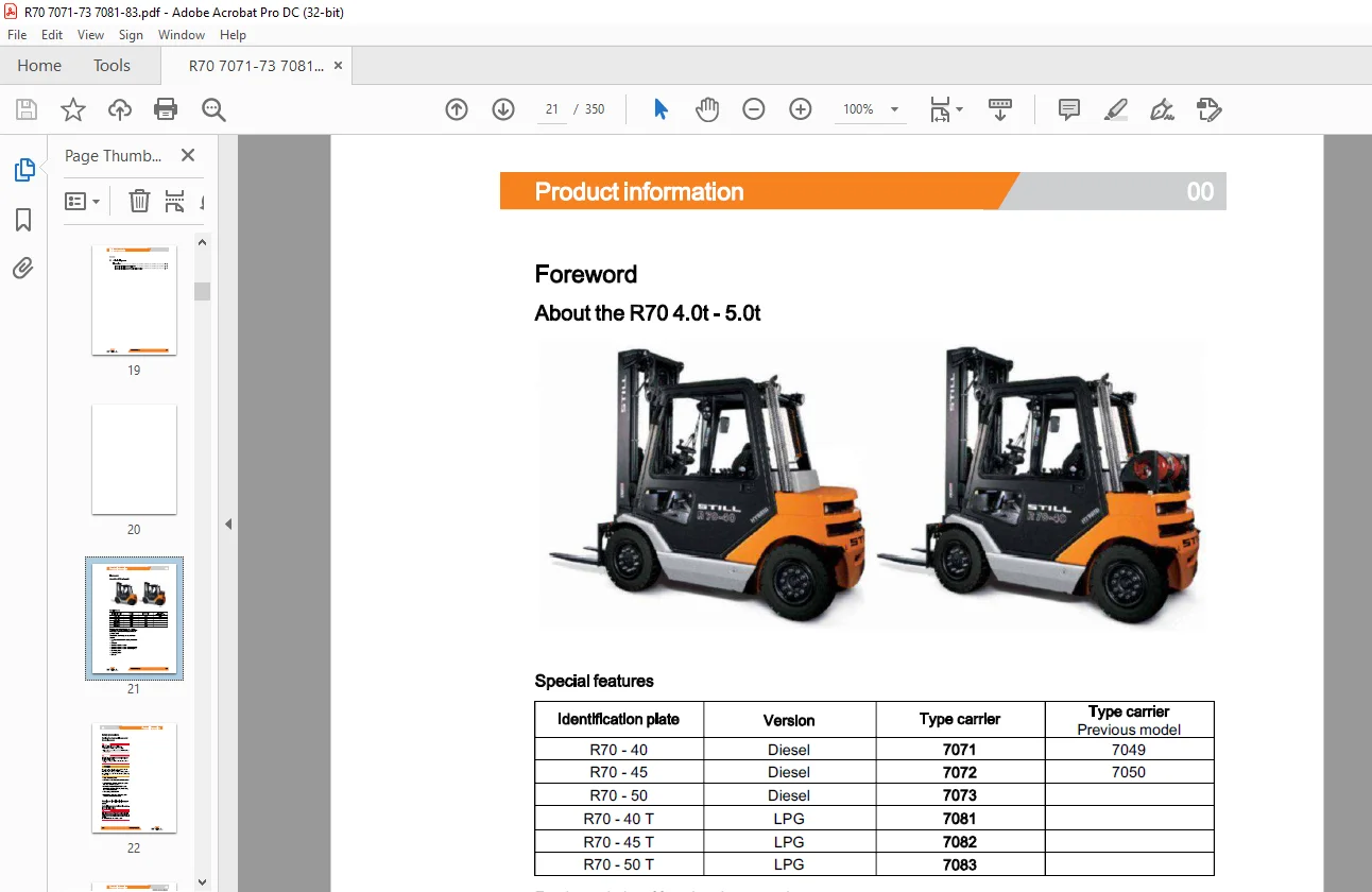
Foreword
About the R70 4.0t – 5.0t
For the majority of functional groups, the type carriers described have most in common with the RX series, despite their traditional chassis and overhead guard.
The following functional groups are similar or
identical:
? Three-phase traction drive with hybrid technology
? Drive axle
? Internal combustion engine
? Internal combustion engine – attachment parts
? Internal combustion engine – exhaust system
? Electrical system
? Hydraulic system
? Lift mast
TABLE OF CONTENTS:
STILL STED Forklift Diesel LPG forklift trucks R70-40 R70-45 R70-50 workshop Manual – PDF DOWNLOAD
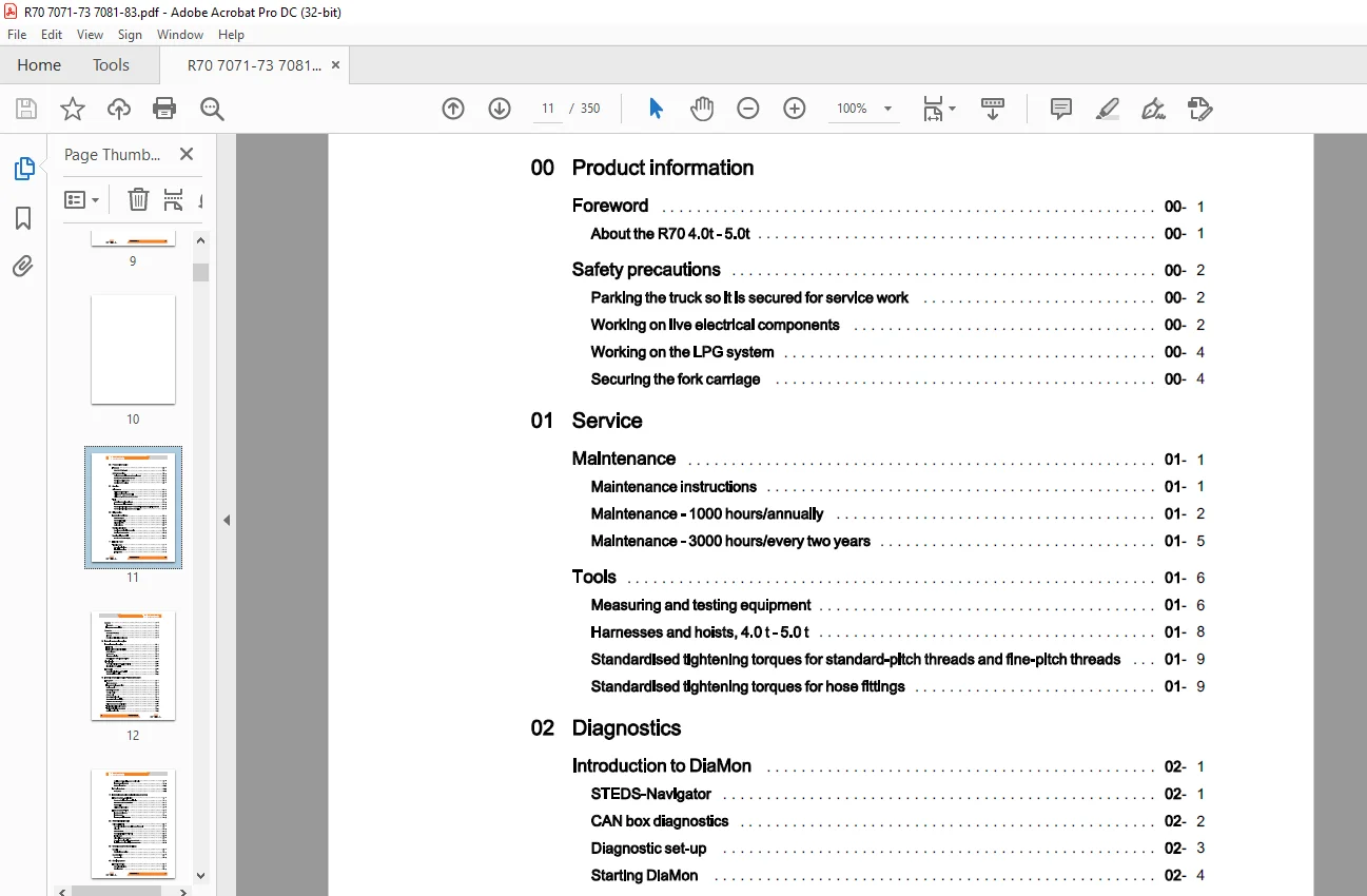
00 Product information
Foreword 00
About the R70 4.0t- 5.0t 00
Safety precautions 00
Parking the truck so it is secured for service work 00
Working on live electrical components 00
Working on the LPG system 00
Securing the fork carriage 00
01 Service
Maintenance 01
Maintenance instructions 01
Maintenance – 1000 hours/annually 01
Maintenance – 3000 hours/every two years 01
Tools 01
Measuring and testing equipment 01
Harnesses and hoists, 4.0 t- 5.0 t 01
Standardised tightening torques for standard-pitch threads and fine-pitch threads 01
Standardised tightening torques for hose fittings 01
02 Diagnostics
Introduction to DiaMon 02
STEDS-Navigator 02
CAN box diagnostics 02
Diagnostic set-up 02
Starting DiaMon 02
Working with DiaMon 02
Reading out and clearing the error list 02
Reading out access codes 02
Working using the ABE 02
Error list on the ABE1 display 02
11 Electric motor
Traction motor 11
General technical data 11
Electrical connections 11
Traction motor 11
X 172651 EN – 08/2016
Table of contents
Sensors 11
Pin sensor 11
Temperature sensor KTY84 11
Generator 11
General technical data 11
Alternator 11
Removing and installing the alternator 11
12 Internal combustion engine
Internal combustion engine 12
Engine unit 12
Engine unitRemoval and installation 12
Starter ring gear 12
Starter motor 12
Alternator monitoring 12
Retrofitting the 110-A alternator for TCU 1 12
Diesel engine 12
General technical dataVW 2.0 I turbodiesel 12
Diesel engine VW 2.01 TDI 12
LPG engine 12
General technical data – VW 3.2 I TG 12
VW VR6 3.21 LPG engine 12
13 Internal combustion engine – attachment parts
LPG system 13
lmpco components 13
Evaporator function – gas mixer 13
Suction module 13
MAP/MAT sensor 0B6 13
Chassis module 13
Actuator unit 13
Gas shut-off valve unit 13
Gas shut-off valve monitoring 13
Shut-down due to lack of gas 13
Maintenance and test specifications 13
Testing for leaks in the LPG system 13
Testing CO level in exhaust gases 13
Servicing the LPG filter 13
172651 EN – 08/2016 XI
Table of contents
Servicing the 30-bar high-pressure relief valve 13
Evaporator – maintenance 13
Safety valve – 1. 7 bar 13
LPG cylinder/tank 13
LPG cylinder 13
14 Internal combustion engine- exhaust system
Exhaust system – particle filter 14
Structure of the Eberspacher particle filter 14
7 .5 kW Eberspacher particle filter 14
Regeneration 14
Maintenance instructions 14
Exhaust system – LPG 14
Lambda control system 14
Lambda sensor 14
Three-way catalytic converter 14
22 Mechanical drive axle
Drive axle ECSOI 22
General technical data Carraro EC 50 I 22
Drive axle 22
Drive wheel unit 22
Removing/installing the drive axle 22
Traction motor 22
Differential gearbox and brake 22
Removal of the differential gearbox and brake 22
Installation of the differential gearbox and brake 22
30 Chassis, bodywork and fittings
Chassis 30
Working with gas springs 30
Counterweight 30
Counterweight 30
42 Steering system
Hydraulic steering 42
General technical data 42
Steering system 42
XII 172651 EN – 08/2016
Table of contents
Steering – error detection 42
Steering unit 42
Priority valve 42
Steering wheel and steering column 42
Steering column 42
Steering axle 42
General technical data 42
Swing axle 42
Removing/installing the swing axle 42
Wheel hub 42
Steering angle 42
Tie rod 42
Axle stub 42
49 Brake system
Mechanical service brake 49
Changing the brake cable Service brake 49
Service brake 49
Removing/installing the service brake 49
Brake sensor 1 B2 49
Handbrake 49
Changing the brake cable Parking brake 49
Parking brake switch 49
50 Controls
Single pedal 50
Accelerator- single-pedal 50
Double pedal 50
Accelerator- dual pedal 50
Controls 50
Multi-levers 50
Joystick 50
Joystick operation 50
Generation 2 mini-lever 50
Generation 2 mini-leverActuation 50
Tip switch 50
Generation 1 mini-lever 50
172651 EN – 08/2016 XIII
Table of contents
Axle assignment 50
56 Display elements
Operating console 56
Direction of travel flasher module (Fabli) 56
Direction of travel flasher display 56
Display 56
Display operating unit (ABE 1) Generation 1 56
ABE 1 Installation and removal 56
60 Electrics/electronics
General 60
General technical data 60
Overview of the controllers 60
Electrical components 60
Software compatibility 60
PAN process 60
Parameter management 60
Error ring buffer 60
Intermediate circuit 60
Insulation measurement 60
Traction motor temperature monitoring 60
Temperature monitoring, traction inverter with air cooling 60
Availability of drive mode and driving behaviour 60
Driving mode – driving behaviour Description 60
Blue-Q=IQ 60
Wiring 60
CAN bus system 60
CAN bus connections 60
Power cables 60
Maintenance guidelines for power cables 60
Repair – Contact elements 60
Electrical system 60
Fusebox 60
Fuses 60
Relays in the fuse box 60
XIV 172651 EN – 08/2016
Table of contents
Other components 60
Option Board 60
CAN-Power-Port (CPP) 60
CPP 1/CPP3 60
CPP2/CPP4 60
Soot CPP (CPP5) 60
Relay-Power-Port 60
64 Electronic controllers
Traction and working hydraulics control 64
Truck control unit (TCU) 64
Truck control unit {TCU) Removal and installation 64
Inverters 64
Inverter 64
lnvertersRemoval and installation 64
Brake resistor 64
69 Batteries and accessories
Starter battery 69
Starter battery 69
70 Hydraulics
General 70
General technical data 70
Depressurising the hydraulics 70
Lifting operating speeds 70
Tilting operating speeds 70
Lowering operating speeds 70
Safety check 70
Forward tilt safety test 70
Lowering safety test 70
Safety checks of hose assembly 70
Basic hydraulics 70
Basic hydraulics 70
Fan motor control unit 70
Fan control valve 70
Steering hydraulics 70
Working hydraulics 70
172651 EN – 08/2016 XV
Table of contents
Variable displacement pump 70
Pump regulator 70
Variable displacement pumpRemoval and installation 70
Hydraulic tank 70
Hydraulic oil 70
Intake filter 70
Suction filter 70
Return filter 70
Breather 70
High-pressure filter 70
Conical nipple fittings (CNF) 70
Bolted joint 70
71 Working hydraulics
Tilt cylinders 71
Mast tilt 71
Tilt cylinders Removal and installation 71
Changing the set of seals2200-5000 kg – LSP 500 71
Auxiliary hydraulics 71
Attachments 71
Second operating function for attachments 71
Clamp locking mechanism for hand levers 71
Clamp locking mechanism with servo hydraulics 71
Accumulator 71
Accumulator 71
Checking the accumulator 71
76 Valves
Hand lever 76
General technical data 76
Hand lever valve block 76
Valve block Removal/ installation 76
Directional control valve block 76
Check valve for hydraulics blocking function 76
Hydraulic transmitter 76
Servo hydraulics 76
General technical data 76
Servo hydraulics valve block 76
Table of contents
Directional control valve block 76
Directional control valve function Lifting 76
Directional control valve function Lowering 76
80 Load lift system
Mast bearings 80
Carraro EC50 and EC50I mast bearings 80
81 Lift mast
Lift mast 81
General technical data 81
Hose safety valve of triplex mast 81
Support roller play ( 150) 81
Load chains – Checking and cleaning 81
Working on lift masts 81
Lift mast – Removal 81
Lift mast- Installation 81
Telescopic lift mast 81
Telescopic lift mast (150) 81
Removing the support rollers in the lift mast 81
Assembling the lift mast after replacing the support rollers 81
Adjusting the load chains Telescopic lift mast (150) 81
Triple mast 81
Triple mast ( 150) 81
Adjusting the outer load chains Triple mast ( 150) 81
Load chain adjustment midpoint Triple mast (150) 81
Lift cylinders 81
Lift jack 81
Working on lift cylinders 81
Outer cylinder 81
84 Load support
Fork carriage 84
Fork carriage – Removing in an upwards direction 84
Fork carriage – Removing in a downwards direction 84
172651 EN – 08/2016 XVII
Table of contents
Annex
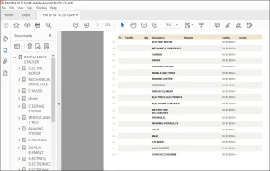
X Circuit diagrams
Hydraulics
Hydraulic circuit diagram Multi-levers
Hydraulic circuit diagram Proportional technology
Contact us: [email protected]
https://vimeo.com/856142468?share=copy
PLEASE NOTE:
- This is the SAME manual used by the dealers to troubleshoot any faults in your vehicle. This can be yours in 2 minutes after the payment is made.
- Contact us at [email protected] should you have any queries before your purchase or that you need any other service / repair / parts operators manual.
S.M