Still STED forklift Dual 15-3 Workshop Manual – PDF DOWNLOAD
$30.95
Still STED forklift Dual 15-3 Workshop Manual – PDF DOWNLOAD
Description
Still STED forklift Dual 15-3 Workshop Manual – PDF DOWNLOAD
FILE DETAILS:
Language : English
Pages : 560
Downloadable : Yes
File Type : PDF
DESCRIPTION:
Still STED forklift Dual 15-3 Workshop Manual – PDF DOWNLOAD
Foreword
IMAGES PREVIEW OF THE MANUAL:
TABLE OF CONTENTS:
Still STED forklift Dual 15-3 Workshop Manual – PDF DOWNLOAD
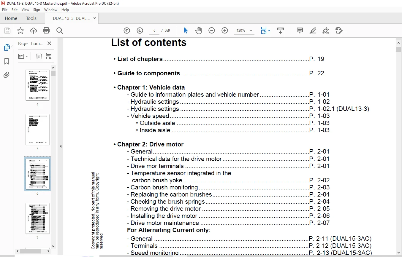
List of contents
• List of chapters P 19
• Guide to components P 22
• Chapter 1: Vehicle data
– Guide to information plates and vehicle number P 1-01
– Hydraulic settings P 1-02
– Hydraulic settings P 1-02 1 (DUAL13-3)
– Vehicle speed P 1-03
• Outside aisle P 1-03
• Inside aisle P 1-03
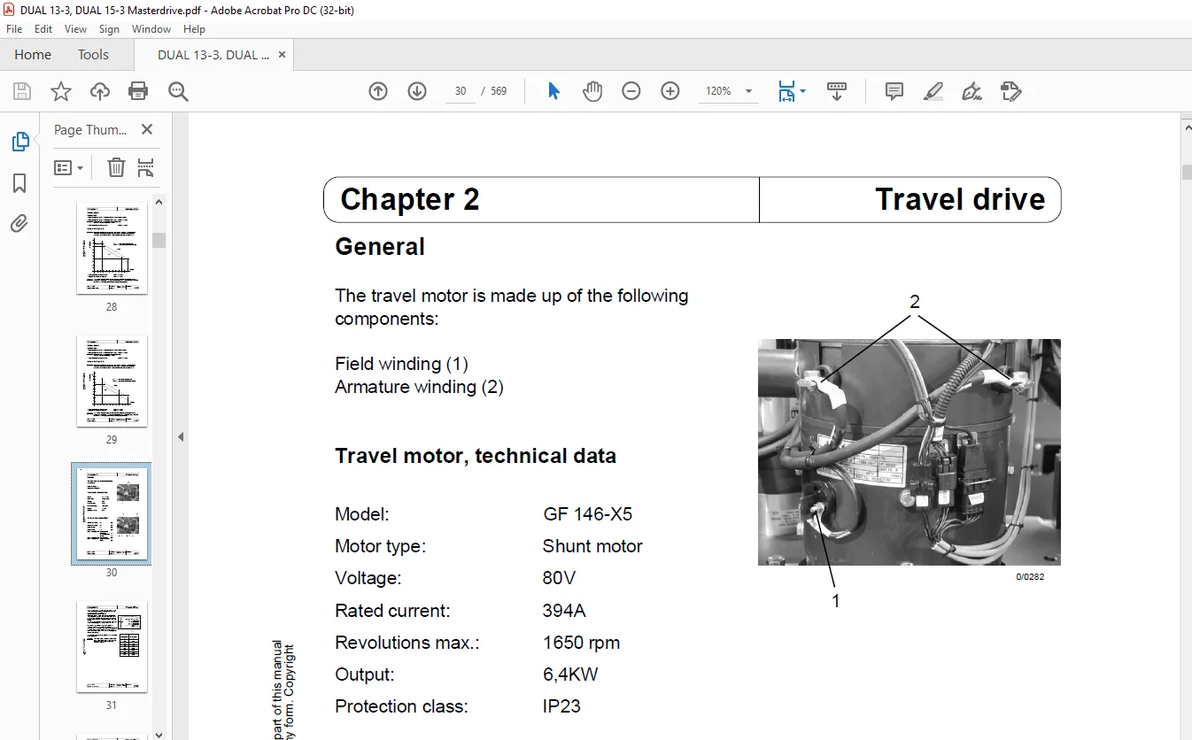
• Chapter 2: Drive motor
– General P 2-01
– Technical data for the drive motor P 2-01
– Drive mor terminals P 2-01
– Temperature sensor integrated in the
carbon brush yoke P 2-02
– Carbon brush monitoring P 2-03
– Replacing the carbon brushes P 2-04
– Checking the brush springs P 2-04
– Removing the drive motor P 2-05
– Installing the drive motor P 2-06
– Drive motor maintenance P 2-07
For Alternating Current only:
– General P 2-11 (DUAL15-3AC)
– Terminals P 2-12 (DUAL15-3AC)
– Speed monitoring P 2-13 (DUAL15-3AC)
– Removal P 2-14 (DUAL15-3AC)
– Technical data P 2-15 (DUAL15-3AC)
– Temperature monitoring P 2-16 (DUAL15-3AC)
– Speed sensor P 2-17 (DUAL15-3AC)
• Removal P 2-17 (DUAL15-3AC)
• Installation P 2-19 (DUAL15-3AC)
• Chapter 3: Drive wheel
– Replacing the drive wheel P 3-01
– Removing the drive wheel P 3-01
– Replacing the idling wheels P 3-02
– Removing the idling wheels P 3-02
– Installing the idling wheels P 3-02
• Chapter 4: Gear
– Oil change P 4-01
– Removing the gear P 4-02
Copyright protected No part of this manual
may be reproduced in any form Copyright
reserved
Issue: 07/03 Workshop Sheet no
Replaces issue: 06/02 Manual DUAL15-3 4
List of contents
• Chapter 5: Brake
– Electromagnetic brake P 5-01
• Function P 5-01
• Removal P 5-02
• Replacing the brake linings P 5-03
• Adjusting the brake clearance P 5-04
• Mechanical brake release P 5-05
• Testing the brake coils P 5-05
• Continuous release of the second stage P 5-06
• Continuous release of the second stage P 5-06 1 (DUAL13-3)
• Measuring the braking deceleration P 5-07
• Checking the braking deceleration P 5-08
• Checking the braking deceleration P 5-08 1 (DUAL13-3)
• Adjusting the braking deceleration P 5-10
• Adjusting the braking deceleration P 5-10 1 (DUAL13-3)
• Chapter 6: Steering
– Adjusting the steering P 6-01
• General P 6-01
• Adjusting sequence P 6-02
• Turning the potentiometer of the steering controller
to the centre position P 6-03
• Adjusting the rotary force at the handwheel P 6-04
• Adjusting the retaining force in the straight-on position P 6-04
• Adjusting potentiometers R11/R12 P 6-05
• Adjusting the setpoint potentiometers P 6-06
• Adjusting the actual value potentiometer (to approx 11/02) P 6-07
• Adjusting the actual value potentiometer (from approx 11/02) P 6-07 1
• Adjusting the max steering angle P 6-08
• Correction of straight-on P 6-09
– Rail guidance P 6-09
– Free travel P 6-09
• Teaching-in the wheel position display P 6-10
– Steering controller P 6-10 1
• Block diagram of steering P 6-10 1
• Block diagram of steering controller P 6-10 2
• Description P 6-11
• Guide to the potentiometer and LEDs P 6-12
• Service switch P 6-12
• Pin assignment P 6-13
• Main current terminals P 6-14
• Maintenance P 6-14 1
– Steering motor P 6-15
• General P 6-15
• Terminal designations on terminal board P 6-15
• Replacing the carbon brushes P 6-15
• Emergency steering P 6-15
• Maintenance P 6-15
Copyright protected No part of this manual
may be reproduced in any form Copyright
reserved
Issue: 07/03 Workshop Sheet no
Replaces issue: 06/02 Manual DUAL15-3 5
List of contents
• Chapter 7: Mast
– Removing the mast P 7-01
– Installing the mast P 7-05
– Mast table P 7-06
• Chapter 8: Vehicle control system 8U60
– General P 8-01
– Description P 8-01
– Replacing the FZS P 8-01 1
– Pin assignment P 8-02
• Chapter 9: Travel and pump controller A10
– General P 9-01
– Terminals P 9-01
– Pin assignment P 9-02
– Block diagram P 9-04
– Signal processing P 9-05
– Response of the main contactors P 9-06
– Control OK P 9-07
– Temperature monitor fo the drive and pump motors P 9-08
• General P 9-08
• Description P 9-08
• Testing the temperature sensors P 9-08
• Contact assignment MARKII P 9-08 1
– Temperature monitor for the travel and pump controller P 9-09
– Carbon brush monitor for the drive and pump motors P 9-10
– Incremental encoder monitor P 9-12
• General P 9-12
• Description P 9-13
• Testing the incremental encoder of the drive motor P 9-14
• Testing the incremental encoder of the pump motor P 9-15
– Instructions for repair P 9-16
• Power unit P 9-16
• Control card P 9-16
• Field regulator P 9-16
– Table of errors P 9-17
– Removing the FPS P 9-18
– Installing the FPS P 9-19
– Removing the control card P 9-20
– Installing the control card P 9-21
– Removing the field regulator P 9-22
– Installing the field regulator P 9-24
For Alternating Current only:
– General P 9-26 (DUAL15-3AC)
– Block diagram P 9-27 (DUAL15-3AC
– Switching on the main contactors P 9-28 (DUAL15-3AC)
• Step-by-step procedure P 9-28 (DUAL15-3AC)
• Activation of the convertors P 9-28 (DUAL15-3AC)
Copyright protected No part of this manual
may be reproduced in any form Copyright
reserved
Issue: 07/03 Workshop Sheet no
Replaces issue: 06/02 Manual DUAL15-3 6
List of contents
– Phase monitoring P 9-29 (DUAL15-3AC)
– Pin assignment for X1 P 9-30 (DUAL15-3AC)
• Chapter 10: Operating console 8U62
– Operating elements P 10-01
– Block diagram P 10-02
– Operating console board P 10-03
– Pin assignment P 10-04
– Keyboard boards 1, 2 and 3 P 10-05
– Operating console display P 10-06
• General P 10-06
• Basic display P 10-07
• Operating hours P 10-07
• Remaining battery capacity P 10-07
• Wheel position display P 10-07
• Display LED for manual steering P 10-08
• Status and maintenance symbols P 10-08
• “Deadman switch not actuated” display P 10-08
• “Creep speed” display P 10-08
• “2-handed operation not actuated” display P 10-09
• “Barrier open” display P 10-09
• “Maintenance” display P 10-09
• “LR80 error” display P 10-09
• “Acknowledgement required” display P 10-10
• “Reserve1” display P 10-10
• “Reserve2” display P 10-10
– Operating console display P 10-11
• Error display P 10-11
• Information display P 10-11 1
• Switching-on test P 10-12
• Switching over the operating console display P 10-12
• LR80 operating status display P 10-12
– Replacing the setpoint potentiometer P 10-13
• Removing the setpoint potentiometer P 10-13
• Installing the setpoint potentiometer P 10-15
• Rough adjustment of the setpoint potentiometer P 10-17
• Fine adjustment of the setpoint potentiometer P 10-19
• Teaching-in the setpoint potentiometer P 10-20
• Operating console display menu P 10-20 1
– LR80 board (option) P 10-22
• Description P 10-22
• Pin assignment P 10-23
• Chapter 11: Load handling control 8U61
– General P 11-01
– Description P 11-01
– Pin assignment P 11-02
Copyright protected No part of this manual
may be reproduced in any form Copyright
reserved
Issue: 07/03 Workshop Sheet no
Replaces issue: 06/02 Manual DUAL15-3 7
List of contents
• Chapter 12: EMERGENCY-STOP and amplifier module 7A22
– General P 12-01
– Description P 12-01
– Pin assignment P 12-02
– Safety relays K33 and K34 P 12-04
– Safety relay K35 P 12-05
– Key switch relay K36 P 12-06
– Relay K37 (steering error) P 12-07
– “Enable hydraulics” signal P 12-08
– Chain monitoring P 12-09
– Adaptation of the steering setpoint P 12-12
– Control of the electromagnetic brake P 12-13
– Evaluation of the potentiometer value for the
height measuring system of themain lift P 12-14
– Adaptation of incremental encoder signals P 12-15
• Chapter 13: Distributor board A13
– General P 13-01
– Structure P 13-02
– Replacement for distributor board A13 P 13-03
• Chapter 14: Negative feeder module A14
– General P 14-01
– Description P 14-01
– Terminals P 14-02
– Pin assignment X1 P 14-02
• Chapter 15: Main contactors K1 and K2
– General P 15-01
– Coil holder suppression P 15-01
– Spacing distance P 15-01
– Contact pressure P 15-01
• Chapter 16: DC/DC converter
– General P 16-01
– Description P 16-01
– Electrical connections P 16-01
– Technical data P 16-01
• Chapter 17: Distance sensor for the main lift
– General P 17-01
– Location P 17-01
– Identification P 17-01
– Technical data P 17-01
– Pin assignment P 17-01
– Monitor P 17-02
– Safety instructions P 17-03
– Description of errors P 17-04
Copyright protected No part of this manual
may be reproduced in any form Copyright
reserved
Issue: 07/03 Workshop Sheet no
Replaces issue: 06/02 Manual DUAL15-3 8
List of contents
– Removing and installing the distance sensor P 17-05
– Repair instructions
• 1 Replacing the potentiometer P 17-06
• 2 Replacing the cable P 17-07
• 3 Replacing the incremental encoder P 17-09
• 4 Replacing the belt P 17-10
• 5 Replacing the spring P 17-11
• Chapter 18: Distance sensor the for additional lift
– General P 18-01
– Monitor P 18-02
• Chapter 19: Distance sensor for swivelling
– General P 19-01
– Monitoring P 19-01
• Chapter 20: Distance sensor for side shifting
– General P 20-01
– Monitor P 20-02
• Chapter 21: SERVICE mode
– Description P 21-01
– Activating SERVICE mode P 21-02
– Deactivating SERVICE mode P 21-02
• Chapter 22: Teaching-in process
– General P 22-01
– Commissioning P 22-02
– Deleting teaching-in values P 22-03
– Preparation for teaching in P 22-04
– Teaching in the main lift distance sensor P 22-04
– Teaching in the additional lift distance sensor P 22-05
– Teaching in the swivelling distance sensor P 22-06
– Teaching in the side shift distance sensor P 22-07
• Chapter 23: Reference sequence
– General P 23-01
– Reference sequence for the main lift P 23-01
– Reference sequence for the additional lift P 23-01
• Chapter 24: Chassis valve block
– Mounting instructions P 24-01
– Functional elements P 24-01
– Setting the maximum pressure P 24-02
– Parameterising the main lift P 24-02
– Soiling indicator P 24-03
– High presure filter P 24-04
• Changing the filter – removal P 24-04
• Changing the filter – installation P 24-04
Copyright protected No part of this manual
may be reproduced in any form Copyright
reserved
Issue: 07/03 Workshop Sheet no
Replaces issue: 06/02 Manual DUAL15-3 9
List of contents
– Removing the chassis valve block P 24-05
– Fine control of lowering main lift P 24-06
• Chapter 25: Attachment valve block
– Mounting instructions P 25-01
– Functional elements P 25-01
– Adjusting work P 25-02
– Parameterising the ancilliary movements P 25-02
• Chapter 26: Pump motor
– General P 26-01
– Technical data for the pump motor P 26-01
– Pump motor terminals P 26-01
– Temperature sensor integrated in carbon brush yoke P 26-02
– Carbon brush monitoring P 26-03
– Replacing the carbon brushes P 26-04
– Checking the brush springs P 26-04
– Pump motor maintenance P 26-05
For Alternating Current only:
– General P 26-06 (DUAL15-3AC)
– Terminals P 26-07 (DUAL15-3AC)
– Speed monitoring P 26-08 (DUAL15-3AC)
– Technical data P 26-09 (DUAL15-3AC)
– Temperature monitoring P 26-10 (DUAL15-3AC)
• Chapter 27: Hydraulic motor
– Function P 27-01
– Commissioning P 27-01
– Technical data P 27-01
– Checking for leaks P 27-02
– Mounting instructions P 27-03
– Removal P 27-03
• Chapter 28: Pump
– Removing the pump P 28-01
– Mounting instructions P 28-01
• Chapter 29: Oil level indicator
– -Oil level indicator P 29-01
• Chapter 30: Ventilation filter
– Function P 30-01
– Removal P 30-01
– Maintenance P 30-01
• Chapter 31: Trilateral head (TLH)
– Adjusting work on the TLH P 31-01
– Adjusting the tooth profile play P 31-02
Copyright protected No part of this manual
may be reproduced in any form Copyright
reserved
Issue: 07/03 Workshop Sheet no
Replaces issue: 06/02 Manual DUAL15-3 10
List of contents
– Adjusting the eccentric rollers for the overshift function P 31-06
– Adjusting the swivel shaft for the additional lift P 31-09
– Removing the lift carriage P 31-11
– Adjusting the radial play on the lift carriage P 31-12
– Adjusting the axial play on the lift carriage P 31-12
– Adjusting the potentiometer for side shifting P 31-14
– Adjusting the poentiometer for swivelling P 31-16
– Adjusting the 90° swivelling range P 31-17
– Adjusting the switching lug for side shifting P 31-18
– Adjusting the limit switches for swivelling P 31-19
– Adjusting the magnetic sensors P 31-20
• Chapter 32: Lubrication plan
– Guide to iols and lubricants P 32-01
– Lubrication plan P 32-02
– Disposal of oils and lubricants P 32-03
• Chapter 33: Chains
– Lifting chains P 33-01
• General P 33-01
• Checking the lifting chains for damage P 33-02
• Checking the chain elongation P 33-06
• Replacing the lifting chains P 33-08
• Lubricating the lifting chains P 33-09
– Cleaning the chains P 33-10
– Roller chains P 33-11
• General P 33-11
• Chapter 34: Inductive automatic steering
– General P 34-01
– Description of the operating modes P 34-02
• Self-test P 34-02
• Manual operation P 34-02
• Automatic operation P 34-03
– Wire search P 34-03
– Preparatory aisle travel P 34-04
– Aisle travel P 34-05
• Switching back to manual steering P 34-06
– Version 10 X P 34-07
• Improved detection mode P 34-07
• Recognition process in the drive wheel
side (DWS) travel direction P 34-08
•Recognition process in the load side (LS) travel direction P 34-09
•1 Very flat approach angle P 34-09
•2 Flat approach angle P 34-09
•3 Steep approach angle to 40° P 34-09
•Displays on operating console during detection
process on detection curves P 34-10
– Block diagram P 34-11
Copyright protected No part of this manual
may be reproduced in any form Copyright
reserved
Issue: 07/03 Workshop Sheet no
Replaces issue: 06/02 Manual DUAL15-3 11
List of contents
-Test operating unit (TBE) P 34-12
•Test mode positions P 34-12
– Guide to components in the automatic inductive steering P 34-13
– Adjusting chart P 34-14
– Checking the mechanical elements P 34-20
• Steering bearing P 34-20
• Gearwheels P 34-20
• Wheels P 34-20
– Checking the LR80 display P 34-21
– LR80 display and LED displays P 34-22
– Balancing the digital filter P 34-23
– Central processing unit – CPU board P 34-24
– Central proccessing unit – DC/DC-converter P 34-25
– Central proccessing unit – baseplate P 34-26
• Counting method for connectors and sockets P 34-27
– Central unit P 34-28
• View from the front with front panel mounted P 34-28
• View from the front with front panel removed P 34-28
• View of the baseplate P 34-28
• Switching outputs P 34-29
• Meaning of the switching outputs P 34-29
• “Steering enable” switching output P 34-29
• Switching outputs P 34-30
– Testing the switching outputs with the
operating mode switch P 34-30
– Testing the speed sensor P 34-31
– Incremental encoder P 34-32
• General P 34-32
• Monitoring P 34-32
– Loading standard parameter set P 34-33
– Language selection P 34-34
– Steering output stage P 34-35
• Setting the service switch P 34-35
• Enable LED P 34-35
• Input/output signals P 34-37
• Signals from the LR80 central processing unit P 34-37
– Maximum steering angle P 34-38
• Allocation of value P 34-40
• Storing P 34-40
– Adjusting the setpoint potentiometer P 34-41
• Adjusting the turning force of the handwheel P 34-41
• Adjusting the retaining force of the centre
detent mechanism P 34-41
• End stop P 34-41
• Adjustment of straight-on travel with the setpoint
potentiometer in centre detent mechanism P 34-41
– Setpoint potentiometer (to approx 11/02) P 34-42
• General P 34-42
– Setpoint potentiometer (from approx 12/02) P 34-42 1
Copyright protected No part of this manual
may be reproduced in any form Copyright
reserved –
Issue: 07/03 Workshop Sheet no
Replaces issue: 06/02 Manual DUAL15-3 12
List of contents
• General P 34-42 1
– Setting the offset potentiometer for “Straight-on in
DWS and LS direction” to “00” P 34-43
-Adjusting the actual value potentiometer (to approx 11/02) P 34-44
-Adjusting the actual value potentiometer (from approx 12/02) P 34-44 1
– Actual value potentiometer (to approx 11/02) P 34-45
• General P 34-45
• Testing the potentiometer P 34-45
– Actual value potentiometer (from approx 12/02) P 34-45 1
• General P 34-45 1
• Testing the potentiometer P 34-45 1
– Guide frequency generator P 34-46
• The frequency generator viewed from the front P 34-46
• Battery buffer P 34-46
• Commissioning the guide frequency generator P 34-47
• Adapting the output filter to a wire loop P 34-48
• Connecting the wire loop P 34-49
– Mounting and adjusting the aerials P 34-50
• 1 Determining the centre marking for mounting the
DWS antennas P 34-50
• 2 Adjusting the DWS antenna P 34-51
• 3 Setting the offset potentiometer for Straight-on
in direction of the drive wheel side” travel P 34-52
• 4 Mounting and adjusting the LS antenna P 34-53
• Setting the offset potentiometer for “Straight-on in
direction of the load side” trave P 34-54
– Aerials P 34-55
• General P 34-55
• Function P 34-55
• Pin assignment P 34-55
• Technical data P 34-55
– Emergency-off parameters P 34-56
• General P 34-56
• XE59 P 34-57
• XE5B P 34-58
• XE5A P 34-59
• XE5D P 34-60
– Steering angle limiter P 34-61
• Description of function / An introduction to the component P 34-61
• Block diagram for vehicles with distributor board A13 P 34-62
• Block diagram for vehicles without distributor board A13 P 34-62 1
• Conditions required for the detent to lock P 34-63
• Conditions required for the detent to release P 34-63
• Pin assignment for connector X1 P 34-64
• Monitoring P 34-65
• Adjustment P 34-66
• Modification to the steering angle limiter P 34-68 1
– Modified trip cams P 34-68 1
– Modified end stop P 34-68 2
Copyright protected No part of this manual
may be reproduced in any form Copyright
reserved
Issue: 07/03 Workshop Sheet no
Replaces issue: 06/02 Manual DUAL15-3 13
List of contents
– Aisle recognition P 34-69
• Aisle recognition sensors P 34-69
• Mounting the reflectors – aisle with two open ends P 34-70
• Mounting the reflectors – aisle with one open end P 34-70
• Aisle recognition error P 34-71
• Aisle recognition signal at LR80 P 34-72
– Table of LR80 situations P 34-73
– Notebook P 34-74
• Preparing for programming the LR80 P 34-74
– Programming/changing parameters/test selection
for LR80 with TEWAK P 34-75
– Storing parameters P 34-78
– Error messages P 34-79
– Test selection with operating mode and frequ switch P 34-82
– Test selection with a notebook P 34-83
– Table for convers from hexadecimal to decimal values P 34-84
• Chapter 35: Error codes
– General P 35-01
– Error classification P 35-01
– Errors in FPS and converters in alternating current vehicles P 35-01
• General P 35-01
• Error classes P 35-01 1
• Cancelling errors P 35-01 1
– Travel errors P 35-02
– Steering errors P 35-04
– Main lift errors P 35-08
– Additional lift errors P 35-10
– Reaching errors P 35-11
– Rotating errors P 35-13
– Errors in synchronours rotating/reaching movement 90°/180° P 35-14
– Error configuration and automatic braking at end of aisle (EASS) P 35-15
– Can bus errors P 35-17
– General errors P 35-18
– Errors in automatic braking at end of aisle (EASS) P 35-22
– Travel and pump controller (FPS) errors P 35-26
– Load handling controls (LAS) errors P 35-45
– Operating console (BPS) errors P 35-49
• Chapter 36: Troubleshooting guide
– Power supply function P 36-01
• General P 36-01
• Battery voltage P 36-02
• Battery voltage after key switch P 36-04
• 1+battery voltage after key switch P 36-05
• 1+24V P 36-06
• 1+battery voltage after 1+24V P 36-07
• EMERGENCY-STOP chain P 36-08
• 2+battery voltage P 36-10
Copyright protected No part of this manual
may be reproduced in any form Copyright
reserved
Issue: 07/03 Workshop Sheet no
Replaces issue: 06/02 Manual DUAL15-3 14
List of contents
• 2+24V P 36-12
• Chapter 37: WINFLASH
– General P 37-01
– Block diagram P 37-02
– Description P 37-03
– Setting up a connection with the vehicle P 37-06
– Loading the vehicle program P 37-07
– Updating programs P 37-09
• Chapter 38: ParaDig 133 / ParaDig 153
– General P 38-01
– Setting up a connection with the vehicle P 38-02
– Opening the software P 38-03
– Starting parameterising and diagnosis P 38-05
– Errors when starting parameterising and diagnosis P 38-06
• Outdated vehicle software P 38-06
• ParaDig does not match the vehicle model P 38-07
– Old software version of vehicle program P 38-09
– Working with ParaDig P 38-10
• Page selection P 38-10
• Parameterising P 38-11
– General P 38-11
– Combination field P 38-12
– Direct entry P 38-13
– Parameter value outside the permissible range P 38-13
– Default value P 38-14
• Saving changes P 38-15
– General P 38-15
– Saving for test purposes P 38-16
– Saving permanently P 38-17
• Loading parameters from the vehicle P 38-18
• Saving vehicle settings in a file P 38-19
• Loading vehicle settings from a file P 38-21
• Diagnosis P 38-22
– Starting diagnosis P 38-22
– Working with diagnosis P 38-23
– Closing diagnosis P 38-23
• Working with ParaDig in offline mode P 38-24
• Closing parameterising and diagnosis P 38-27
• Closing the ParaDig service software P 38-28
• Chapter 39: Telescopic fork
– Functional description P 39-01
– Component names P 39-01
– Home position P 39-03
– Measurement of the extension depth Distance sensor P 39-04
– Adjusting the middle carriage P 39-05
– Adjusting the upper carriage P 39-06
Copyright protected No part of this manual
may be reproduced in any form Copyright
reserved
Issue: 07/03 Workshop Sheet no
Replaces issue: 06/02 Manual DUAL15-3 15
List of contents
– Adjusting the position switch for the home position P 39-07
– Adjusting the distance sensor for reaching P 39-08
– Teaching in the distance sensor for reaching P 39-09
• Set vehicle control system to SERVICE mode P 39-09
• Delete values that are already taught in P 39-09
• Teach in the distance sensor for reaching again P 39-10
– Parameterising P 39-11
– Definitions P 39-11
– Maximum mech extension parameter P 39-12
– Monitoring of the distance sensor for reaching P 39-13
– Load handling controls LAS P 39-14
– Attachment valve block P 39-15
– Additional lift distance sensor P 39-16
• Monitoring P 39-17
• Teaching in the additional lift distance sensor P 39-17
– Maintenance instructions for drive chains and
return chains P 39-18
– Reliable lubricants and mineral oils P 39-19
• Chapter 40: Filling aid
– Functional description / Component names P 40-01
– Preparation P 40-02
– Draining hydraulic oil out of the tank P 40-03
– Filling the tank with hydraulic oil P 40-04
• Chapter 41: Converter (for Alternating Current only)
– General P 41-01 (DUAL15-3AC)
– Testing the CAN bus P 41-04 (DUAL15-3AC)
– Speed monitoring P 41-06 (DUAL15-3AC)
– Speed sensor P 41-07 (DUAL15-3AC)
– Temperature monitoring P 41-08 (DUAL15-3AC)
• Testing the temperature sensors P 41-08 (DUAL15-3AC)
– Charging the bank of capacitors P 41-09 (DUAL15-3AC)
– Discharging the bank of capacitors P 41-10 (DUAL15-3AC)
– Function of the LED P 41-11 (DUAL15-3AC)
– Main current terminals P 41-12 (DUAL15-3AC)
– Power recovery P 41-13 (DUAL15-3AC)
– Pin assignment P 41-14 (DUAL15-3AC)
• X1 P 41-14 (DUAL15-3AC)
• Chapter 42: Panel
– Main current component panel (to approx 11/02) P 42-01
– Control current component panel (to approx 11/02) P 42-02
– Component panel (form approx 12/02) P 42 02 1
– Main current component panel P 42-03 (DUAL15-3AC)
Copyright protected No part of this manual
may be reproduced in any form Copyright
reserved
Issue: 07/03 Workshop Sheet no
Replaces issue: 06/02 Manual DUAL15-3 16
List of contents
• Chapter 43: EASS
– EASS inductive P 43-01
• General P 43-01
• Setting the “EASS inductive” option P 43-02
• Proximity switches P 43-03
• Calculating the length of the steel plates P 43-04
• Calculating the maximum braking distance P 43-04
• Mounting the steel plates P 43-05
– Without absolute stop P 43-05
– With absolute stop at closed aisle end only P 43-07
– Without absolute stop at the open and closed aisle end P 43-09
• Division into zones / General P 43-10
– General P 43-10
– Zone 0 P 43-10
– Zone 1 P 43-11
– Zone 2 P 43-12
– Zone 3 P 43-13
– Zone 4 P 43-14
– Zone 5 P 43-15
– Guide to maximum speeds in the various zones P 43-15
• Suppression of metal elements that cause interference P 43-16
• Diagnosis P 43-17
– EASS magnetic P 43-18
• General P 43-18
• Setting the “EASS magnetic” option P 43-19
• Magnetic switches P 43-20
– General P 43-20
– Mounting the switches P 43-21
• Switching magnets P 43-22
– General P 43-22
• Calculating the maximum braking distance P 43-23
– Definitions P 43-23
• Mounting the switching magnets P 43-24
– Without absolute stop P 43-24
– With absolute stop at closed aisle end only P 43-26
• Division into zones P 43-28
– General P 43-28
– Zone 0 P 43-29
– Zone 1 P 43-30
– Zone 3 P 43-31
– Zone 5 P 43-32
• Diagnosis P 43-33
– EASS reflexli P 43-34
• General P 43-34
• Setting the “EASS reflexli” option P 43-35
• Reflector types P 43-36
– Reflector types A and B P 43-36
– Reflector type C – Check P 43-36
Copyright protected No part of this manual
may be reproduced in any form Copyright
reserved
Issue: 07/03 Workshop Sheet no
Replaces issue: 06/02 Manual DUAL15-3 17
List of contents
– Reflector type C – Stop P 43-37
– Reflector type D4 – Absolute stop P 43-38
• Mounting heights for reflector installation
on the shelves – both sides P 43-39
• Mounting heights for reflector installation
on the shelves – one side P 43-40
• Reflective light barriers P 43-42
– Arrangement of the reflective light barriers
for automatic braking at the aisle end P 43-42
– Arrangement of the reflective light barriers for automatic
braking at he aisle end, stop and absolut stop and check P 43-42
– Arrangement of the reflective light barriers for reflector
installation on one side of the aisle with automatic
braking at the aisle end P 43-43
– Arrangement of the reflective light barriers for reflector
installation on one side of the aisle with automatic
braking at the aisle end, stop and absolute stop and check P 43-44
• Calculating the maximum braking distance P 43-45
– Definitions P 43-45
• Mounting the reflectors P 43-46
– Arrangement of the reflectors for automatic end of
aisle braking P 43-46
– Arrangement of the reflectors for automatic end of
aisle braking and speed monitoring P 43-47
– Arrangement of the reflectors for automatic end of
aisle braking and stop P 43-48
– Arrangement of the reflectors for automatic end of
aisle braking and absolute stop P 43-49
• Division into zones P 43-50
– General P 43-50
– Zone 1 P 43-51
– Zone 0 P 43-52
– Zone 2 P 43-53
• Important rules P 43-54
• Diagnosis P 43-56
• Chapter 44: Individual driving settings
– General P 44-01
– Setting the “Individual driver settings” option P 44-02
– Changing the speed settings for the hydraulic functions P 44-03
– Changing the speed settings for travel P 44-04
Changing the Optispeed adaptation P 44-05
– Saving the changed speed settings P 44-06
– Setting ranges P 44-07
– Diagnosis P 44-08
Copyright protected No part of this manual
may be reproduced in any form Copyright
reserved
Issue: 07/03 Workshop Sheet no
Replaces issue: 06/02 Manual DUAL15-3 18
List of contents
List of chapters
Chapter 1: Vehicle data
Chapter 2: Drive motor
Chapter 3: Drive wheel
Chapter 4: Gear
Chapter 5: Brake
Chapter 6: Steering
Chapter 7: Mast
Chapter 8: Vehicle control system (FZS)
Chapter 9: Travel and pump controller (FPS)
Chapter 10: Operating console
Chapter 11: Load handling control (LHC)
Chapter 12: EM -STOP and amplifier module (NAV)
Chapter 13: Distributor board
Chapter 14: Negative feeder module
Chapter 15: Main contactors
Chapter 16: DC/DC converter
Chapter 17: Distance sensor for main lift
Copyright protected No part of this manual
may be reproduced in any form Copyright
reserved
Issue: 07/03 Workshop Sheet no
Replaces issue: 06/02 Manual DUAL15-3 19
List of chapters
List of chapters
Chapter 18: Distance sensor for additional lift
Chapter 19: Distance sensor for swivelling
Chapter 20: Distance sensor for side shifting
Chapter 21: SERVICE mode
Chapter 22: Teaching-in process
Chapter 23: Reference sequence
Chapter 24: Chassis valve block
Chapter 25: Attachment valve block
Chapter 26: Pump motor
Chapter 27: Hydraulic motor
Chapter 28: Pump
Chapter 29: Oil level indicator
Chapter 30: Ventilation filter
Chapter 31: Trilateral head TLH
Chapter 32: Lubrication plan
Chapter 33: Chains
Chapter 34: Inductive automatic steering
Chapter 35: Error codes
Copyright protected No part of this manual
may be reproduced in any form Copyright
reserved
Issue: 07/03 Workshop Sheet no
Replaces issue: 06/02 Manual DUAL15-3 20
List of chapters
List of chapters
Chapter 36: Troubleshooting guide
Chapter 37: WINFLASH
Chapter 38: ParaDig 133 / ParaDig 153
Chapter 39: Telescopic fork
Chapter 40: Filling aid
Chapter 41: Converter (AC only)
Chapter 42: Panel
Chapter 43: EASS
Chapter 44: Individual driving settings
Guide to components
• Drive wheel P 3-01
• Operating console 8U62 P 10-01 ff
• DC/DC converter U30 P 16-01
• Electromagnetic brake 1Y44 P 5-01 ff
• Drive motor 1M3 P 2-01 ff
• Travel and pump controller A10 P 9-01 ff
• Vehicle control system 8U60 P 8-01 ff
• Fine control of lowering main lift P 24-06
• Gear P 4-01 ff
• Main contactors K1 and K2 P 15-01
• Distance sensor for the main lift P 17-01 ff
• Distance sensor for the additional lift P 18-01 ff
• Hydraulic motor P 27-01 ff
• Load handling control 8U61 P 11-01 ff
• Steering motor 3M1 P 6-15
• Steering controller 3A20 P 6-11 ff
• Oil level indicator P 29-01
• Pump motor 2M1 P 26-01 ff
• Negative feeder module A14 P 14-01
• Trilateral head P 31-01 ff
• Attachment valve block P 25-01 ff
• Chassis valve block P 24-01 ff
• Distributor board A13 P 13-01 ff
• Distance sensor for shifting P 20-01 ff
• Distance sensor for swivelling P 19-01
• EMERGENCY-STOP and amplifier module 7A22 P 12-01 ff
• Telescopic fork P 39-01 ff
• Panel P 42-01 ff
Need help? Contact: [email protected]
https://vimeo.com/855720720?share=copy
PLEASE NOTE:
- This is the SAME exact manual used by your dealers to fix your vehicle.
- The same can be yours in the next 2-3 mins as you will be directed to the download page immediately after paying for the manual.
- Any queries / doubts regarding your purchase, please feel free to contact [email protected]
S.M