Still STED forklift DUAL10 13-N Workshop Manual – PDF DOWNLOAD
$28.95
Still STED forklift DUAL10 13-N Workshop Manual – PDF DOWNLOAD
Description
STILL STED FORKLIFT DUAL10 13-N WORKSHOP MANUAL – PDF DOWNLOAD
FILE DETAILS:
STILL STED forklift DUAL10 13-N workshop Manual – PDF DOWNLOAD
Language : English
Pages : 381
Downloadable : Yes
File Type : PDF
IMAGES PREVIEW OF THE MANUAL:
DESCRIPTION:
STILL STED forklift DUAL10 13-N workshop Manual – PDF DOWNLOAD
Foreword
TABLE OF CONTENTS:
STILL STED forklift DUAL10 13-N workshop Manual – PDF DOWNLOAD
A
Absolute stop C11, C16, C19
Acknowledgement key C13, M32, V43
Acoustic signal, LR80 I6, I13
Actual value B7
Actual value error B6
Actual value potentiometer B2, B3, B16
Actual value potentiometer, LR80 I15, I16, I20, I46 ff
Actual value potentiometer, offset potentiometer B6
Additional lift, removal F5
Additional lift cylinder F5 ff
Adjusting chart LR80 I17 ff
Adjusting potentiometer, steering angleB6, B12, B17
Aerials I4, I5, I14 ff, I57
Aerial adjustment I21, I52 ff
Aisle detection B2, I14, I16, I72 ff
Aisle detection, testing I22
Aisle detection, mounting the reflectors I75
Aisle detection sensors I15, I74
Aisle travel, LR80 I8
All-purpose grease A9, R2
Analogue module, PLC V4
Application program, copying, PLC V18 ff
Application program, PLC V15 ff
Armature shaft A6
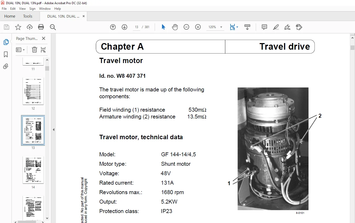
Armature winding, travel motor A2, A14
Attachment E2
Automatic operation, LR80 I6
B
Ball bearings, travel motor A16
Ball bearings, steering motor B19
Barrier switches (S20 and S21) M13
Base plate, LR80 I29, I30
Battery buffer, LFG I49
Battery roller track E4
Battery type, FPS M62
Battery lock E4
Battery status display M42
Bearing play, idling wheel E11
Bearing shell, load carriage E2, E3, E6
Binary module, PLC V4
Bleeder screw, main lift F4
Bleeder screw, additional lift F6
Block diagram, operating console M34
Block diagram, FPS M49
Block diagram, hydraulics N2
Block diagram, logic 7A21 M19
Block diagram, LR80 I14
Block diagram, standard steering B2
Bogie bearing A9
Brake lining, replacing C4
Brake, removal C3
Brake, function C2
Brake, generator C10
Brake, clearance C5, C9
Brake, mech release C6
Brake modes C10
Brake stage C8, C9
Brake amplifier (1U21) M26
Brake deceleration C7 ff
Braking distance C15
Braking zone C11, C19
Brush spring A11
Brush spring, testing A12
B/W valve, lifting main lift (2Y20) N5, N6
B/W valve, lowering main lift (2Y21) N5, N6
B/W valve, ancillary movements (2Y22) N5, N6
C
Carbon brushes, travel motor A11, A12
Carbon brushes, steering motor B19, B20
Carbon br monitor, travel motor A2, A11, M58, M69
Carbon br monitor, pump motor M58, M69
Carbon dust A12
Chain breakage M21
Chain breakage function, checking M23
Chain breakage switch (2S60, 2S61) M6, M21, M22
Chain breakage monitor M16, M21
Chain joint B11
Chain tensioner B10, B11
Chain tension B10, B11
Chassis E2, E6
Chassis distributor board (A21) A4, M7, M14, M27 ff
Central processing unit (3A21), LR80 I14 ff, I30 ff
Commutator, travel motor A16
Connections, travel motor A2
Connector, counting method, LR80 I32
Control board (3A24) I67
Control unit, FPS M47
Control system OK A3, M50
CPU module, PLC V4
CPU board, LR80 I18, I27, I30
Curve number, LR80 I13
Cylinders, main lift E4, E6, F3 ff
Cylinder support F2, F4
Cylinder holder, main lift F3
Copyright protected No part of this manual
may be reproduced in any form Copyright
reserved
Issue: 10/99 Workshop Sheet no
Replaces issue: 10/98 Manual
Key words
DUAL10/13-N VI
D
DC/DC converter (U30) M7, M8, M14
Deadman’s switch (1S25) M12
Deceleration 1 (0 km/h) M54, M55
Deceleration 2 (2 5 km/h) M54, M56
Deceleration 3 (1 km/h) M54, M56
Delay parameter C10
Detection, reverse I10, I12
Detection, improved I10
Detection, forwards I10, I11
Detection curve I11, I12
Detection angle <10° I6
Detection angle >10° I6
Detent control I69 ff
DIAG LED, PLC V10
Digsy software V12
Direction of rotation, travel motor A3
Direction of travel, FPS M52
Disposal, oils R3
Disposal, lubricants R3
Distributor, PLC (A40) M7, M14, M30
Distributor board (A23) M4, M31
DRH-CS2 module N2, N3, N12 ff
Drive wheel A10
Drive pinion A6, A7
E
Eccentric cam E2, E3
Electrical switchboard M14
Emergency stop C13, M18
Emergency release valve N6, N8
Emergency-off parameter I22, I35, I58 ff
End stop, handwheel B13
Error display, operating console M45
Error bit, PLC C13, V43, V44
Error bit bar, reading out, PLC V45 ff
Error bit bar, PLC C13, V43
Error class, operating console M45
Error message, LR80 I83 ff
Error memory M64
Error memory, error description M66 ff
Error memory, error list M65
Error memory, deleting M64
Eyebolt M8 A6
F
Fast travel zone C12, C13, C17 ff
Field connection, steering motor B19
Field winding, travel motor A2
Four-point bearing A7
FPS, selecting travel parameters M57
FPS, battery type M62
FPS, description M50
FPS, changing operating hours M63
FPS, travel programs M53
FPS, deceleration 1, 2 and 3 M54
FPS, direction of travel M52
FPS, error description M66 ff
FPS, error list M65
FPS, error memory M64
FPS, carbon brush monitor M58
FPS, power section M47
FPS, travel setpoint M51
FPS, hydraulic function setpoint M58
FPS, reading out set values M69
FPS, standard parameter set M62
FPS, status displays M60
FPS, pin assignment M48
FPS, control and logic section M47
FPS, temperature monitor M59
FPS, summary of all addresses M70
FPS, summary of all travel parameters M71
Frequency switch I18 ff,I27, I30
Fuse F1, main current switchboard M7 ff
Fuse F2, main curernt switchboard M7 ff
G
Gear, removal A8
Gear, oil change A9
Guide to addresses, FPS M70
Guide block, SSG T4
Guide rollers, SSG T2
Guide rollers, telescopic load carriage E7 ff
Guide to chapters 0
Guide wire I4
Guide frequency generator (LFG) I15, I20, I48 ff
H
HMC-33 module N2, N4, N5 ff
Hydraulic unit N4
Hydraulic unit, removal N17
Hydraulic enable M16, M21, M22
Hydraulic motor (2M1) N18
Hydraulic motor N3, T10
Copyright protected No part of this manual
may be reproduced in any form Copyright
reserved
Issue: 10/99 Workshop Sheet no
Replaces issue: 10/98 Manual
Key words
DUAL10/13-N VII
I
Idling wheel E11, I23
Interface adapter I78
Interlock module 8U40 C40 ff
Intermediate lift cut-out F4
K
Keypad board 1, 2 and 3 M37
L
Language selection, LR80 I36
Lateral guide rollers, swivel shift fork T2
Line break protection E8, F8 ff
Load carriage E2
Load carriage, removal E6
Load chain E7, E12
Loading-bearing rollers, swivel shift fork T2
Loop current, guide frequency generator I48, I50
Lowering brake valve F6, F10
LR80 display I18, I24 ff
LR80 parameters, guide I80
Lubricating nipple A9
Lubrication plan A9, R3
Lubricants, guide R2
M
Magnetic switc C25, C28
Main contactors (K1, K2) M7, M8, M9, M10 ff
Main current fuse (F1) M7, M8, M9
Maintenance work, travel motor A13 ff
Maintenance work, steering motor B19
Maintenance symbol, operating console M42
MANUAL/AUTO switch I6, I9
Manual operation, LR80 I5
Manual steering B5, I9
Marker, PLC C17, C18, V28
Marker word table, PLC V49
Mast yoke E2
Mechanical release, brake C6
Mica A16
N
Notebook, test numbers, LR80 I18 ff
O
OFF-1 M61
ON-1 M60
ON-2 M61
Offset potentiometer, actual value B6, B12, B18
Offset potentiometer, reverse, LR80 I20, I27, I45, I56
Offset potentiometer, setpoint B6, B12, B18
Offset potentiometer, forward, LR80 I20, I27, I45, I54
Oil drainage screw, gear A9
Oil types, guide R2
Oil filler cap, gear A9
Oil filter, hydraulic oil N4, N16
Oil level, checking, hydraulic oil N16
Oil temperature A9
Oil change, gear A9
Operating lever M39
Operating lever, removal M40
Operating console (A29) B2, I14, M4, M32 ff
Operating console, versions M33
Operating console, operating elements M32
Operating console, start-up test M44
Operating console, error display M45
Operating console board B14, M35
Operating mode switches I18 ff, I27, I30
Operating hours, changing M63
Operating hours, display M42
Output filter, LFG I48
Outer mast E7,E8
Parameters, storing, LR80 I81 ff
Parameters, reading out, FPS M75
Parameters, programming, FPS M76
Parameter changes, PLC V21 ff
Parameter settings, TEWAK95 M77
Parameter EPROM I10, I27
Pin assignment, control board (3A24) I68
Pin assignment, operating console (A29) M36
Pin assignment, logic section, FPS M48
Pin assignment, safety relay board (7A21) M17
Plate offset, ZAG C15
PLC B2, I14, M14
PLC, outputs V6 ff
PLC, inputs V6 ff
PLC, front panel V5
PLC, commissioning V2 ff
PLC, current flow diagram V37 ff
Position switch 0 5 m (1S20) M6, M19, M20
Position switch 3 0 m (1S21) M6, M19, M20
Position switch 4 5 m (1S22) M6, M19, M20
Position switch, combinations M20
Position switch plausibility M16
Potentiometer R19/R20 B14, B17, I44
Potentiometer, travel M38
Potentiometer, hydraulics M38
Power chain N3
Power unit, travel and pump control system M47
Preparatory aisle travel I7, I11 ff
Pressure relief valve, HMC-33 N6
Program, loading into PLC V33 ff
Programming adapter V11
Programming, LR80 I78 ff
Programming, PLC V21 ff
Programming, preparation, FPS M72
Proportional valve, lifting (2Y40) N5, N6
Proportional valve, lowering (2Y41) N5, N6
Proportional valve, technical data N9
Proportional amplifier (2U40) M26
Proximity switch C16, C19, E4
Pulling cylinder F7, N3, T7
R
R19 / R20 B17
Rail travel B5
Rail switch B2, B5, C12, C16 ff
Reflective light barriers C36
Reflector A C37, I74
Reflector B C37, I74
Reflector assembly C37, I75
Relay K35 M25
Retaining force, handwheel B13, I43
Rope (pulley) A6, A8
S
Safety relay K33, K34 M25
Safety relay board (7A21) M7, M8, M14, M16 ff
Safety relay board (7A22) M7, M8, M14, M25
Screw fixant E7
Sealing ring, gear oil A9
Self-test, LR80 I5, I10
Sensor signals, speed sensor A4
Service switch B6, B9, B16, B17, I37
Service hours M63
Setpoint, hydraulic functions M58
Setpoint B7, B14
Setpoints, reading out, FPS M69
Setpoint error B6
Setpoint potentiometer (3R10) B3, B4, B9, B15, I5,
I9, I15, I16, I20, I25, I43, I44
Shaft coupling, swivel shift fork T5 ff
Slack chain, checking M23
Slack chain M21
Sockets, counting method, LR80 I32
Special workshop A13
Speed code M26, M53
Speed, travel motor A3
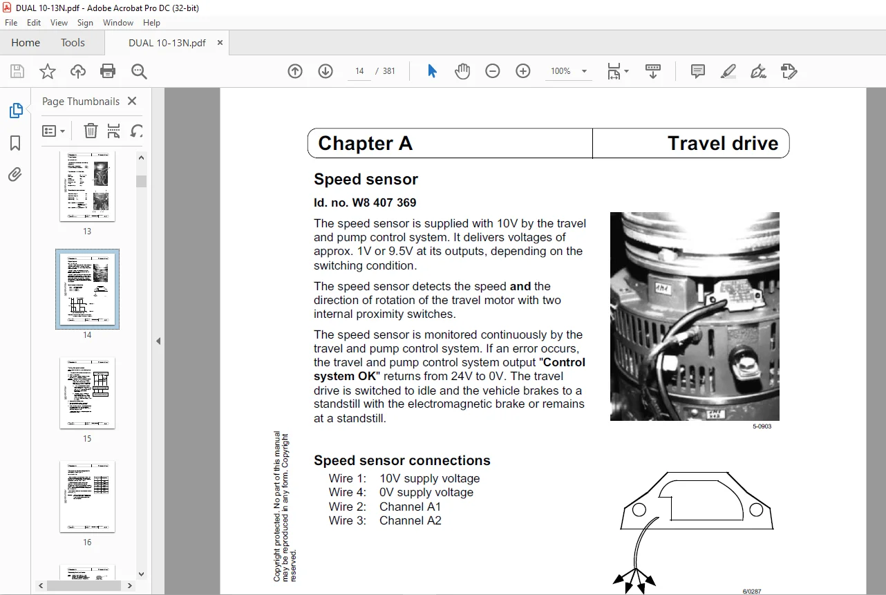
Speed sensor A3, I15, I19, I34
Speed sensor, adaptation M24
Speed sensor, connections A3
Speed sensor, direction of travel M24
Speed sensor, testing A4, I33
ST-STAT M60
Stability C8
Standard parameter set, FPS M62
Standard parameter set, LR80 I19, I35
Status symbols, operating console M43
Steering output stage I14, I15, I16, I19, I37 ff
Steering chain B10, B11, I23
Steering bearing I23
Steering mechanism B9, I18, I23
Steering motor (3M1) B2, B19, I14, I15, I16
Steering motor fuse (3F1) M7, M8, M9
Steering potentiometer (3R11) B14
Steering controller (3A20) B2, B3 ff
Steering relay (3K11) B2, B3, B7, I14, M29
Strng contactor (3K1) B2, B3, B7, I14, M7, M8, M9
Steering, adjustment B9
Steering angle B17, I19, I40 ff
Steering angle limitation, LR80 I14, I15, I22, I63 ff
Steering angle limitation, 3A24 I14, I67 ff, M14
Stop valve, main lift E4, E6, F3
Stop buffer, SSG E10
Support carriage E9
Support rollers E7 ff
Switching outputs, LR80 I31 ff
Switch transistors, LR80 I27
Swivel shift fork (SSF) E10
Swivel shift fork, removal T9
Swivel shaft, SSF F5
SWR module N2, N3, N10 ff
Tank, hydraulic oil N4
Technical data, aerial I57
Technical data, travel motor A2
Technical data, hydraulic motor N19
Technical data, steering motor B20
Technical data, guide frequency generator I51
Telescopic fork Q1ff
Telescopic load carriage E7 ff
Telescopic mast E7 ff
Temperature sensor, travel motor A2, A5
Temperature monitor, travel motor M59
Temperature monitor, FPS M59
Temperature monitor, pump motor M59
Temporary stop C11, C17
Test transmitter, LR80 I5
Test coil, aerial I57
Test connection, manometer N6
Test template, steering angle limitation I63
Tooth profile play, swivel-shift fork T3
Toothed rack, swivel-shift fork E10
Toothed shaft, swivel-shift fork T8
Track rollers E7
Travel and pump control system (FPS) M46, M50
Travel motor (1M1) A2
Travel motor, removal A6 ff
Travel motor, maintenance A13 ff
Travel parameter M57
Travel setpoint, travel and pump control system M51
Turning force, handwheel B13, I43
W
Wheel bearing, idling wheel E11
Wheel position display M42
Wire loop, LFG I51
Wire search, LR80 I6
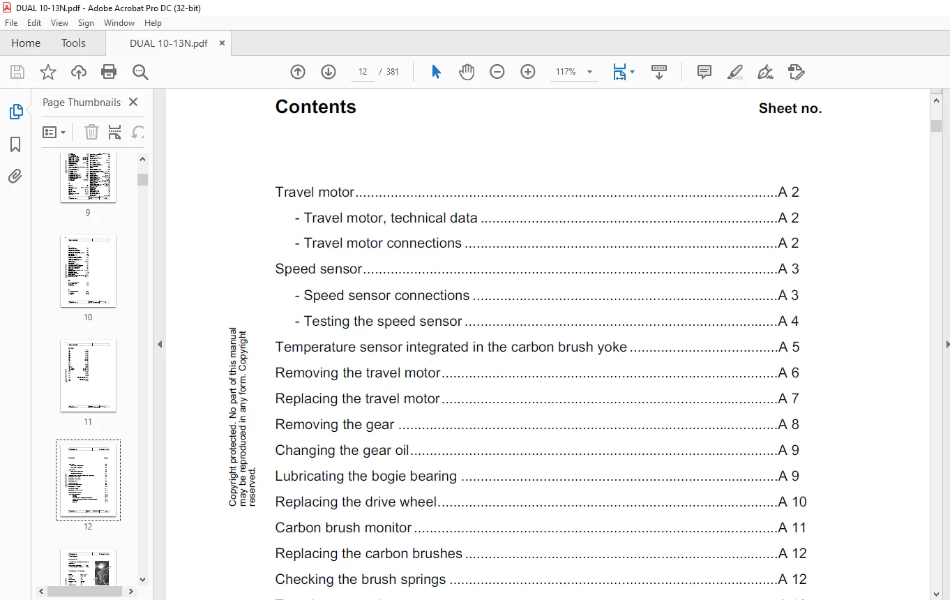
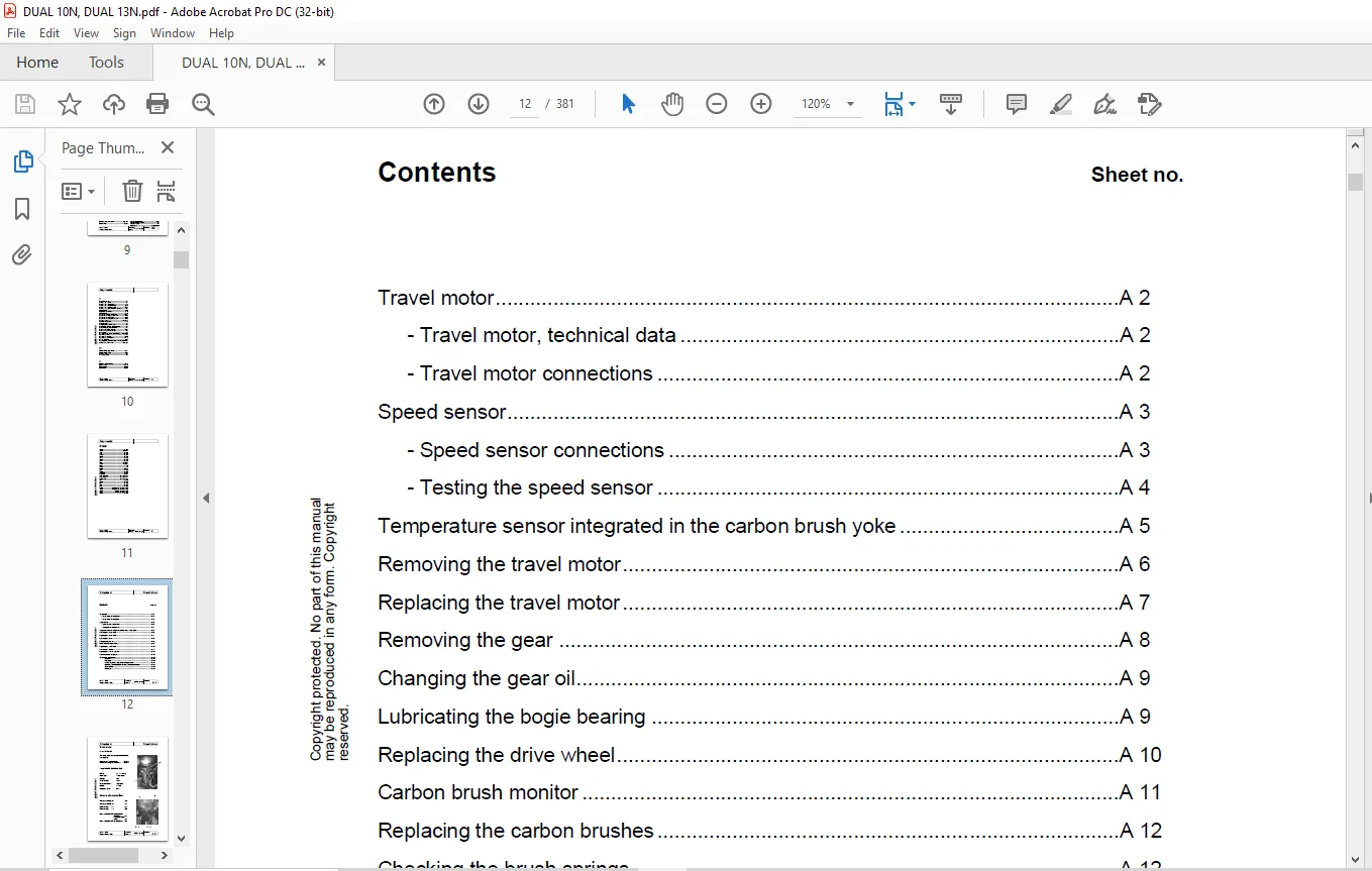
Travel motor A 2
– Travel motor, technical data A 2
– Travel motor connections A 2
Speed sensor A 3
– Speed sensor connections A 3
– Testing the speed sensor A 4
Temperature sensor integrated in the carbon brush yoke A 5
Removing the travel motor A 6
Replacing the travel motor A 7
Removing the gear A 8
Changing the gear oil A 9
Lubricating the bogie bearing A 9
Replacing the drive wheel A 10
Carbon brush monitor A 11
Replacing the carbon brushes A 12
Checking the brush springs A 12
Travel motor maintenance A 13
– General A 13
– Cleaning A 13
– Visual inspection, replacing damaged parts A 14
– Checking the brush unit, replacing the carbon brushes A 15
– Commutator A 16
– Bearings A 16
Need help? Contact: [email protected]
PLEASE NOTE:
- This is not a physical manual but a digital manual – meaning no physical copy will be couriered to you. The manual can be yours in the next 2 mins as once you make the payment, you will be directed to the download page IMMEDIATELY.
- This is the same manual used by the dealers inorder to diagnose your vehicle of its faults.
- Require some other service manual or have any queries: please WRITE to us at [email protected]
S.M