STILL STED Forklift Electric trolleys and tow tractors R07, R08 workshop Manual -PDF DOWNLOAD
$26.95
STILL STED Forklift Electric trolleys and tow tractors R07 R08 workshop Manual -PDF DOWNLOAD
Description
STILL STED Forklift Electric trolleys and tow tractors R07, R08 workshop Manual -PDF DOWNLOAD
FILE DETAILS:
STILL STED Forklift Electric trolleys and tow tractors R07, R08 workshop Manual -PDF DOWNLOAD
Language : English
Pages : 222
Downloadable : Yes
File Type : PDF
DESCRIPTION:
STILL STED Forklift Electric trolleys and tow tractors R07, R08 workshop Manual -PDF DOWNLOAD
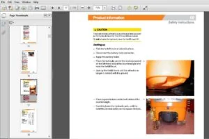
Safety
Working on the electrical system
Working with the converters
Due to the internal energy storage system in converters and control units, there may be dangerously high voltages at the electrical connections in the event of a fault, even after the battery male connector has been disconnected.
Do not touch live contact points such as the positive and negative connections of the power control units! Before working on electrical power connections, always check the voltage between all contact points and between the contact points and the truck chassis using a suitable measuring device (capable of measuring up to 1000 V/DC). Discharge the intermediate circuit
Documentation
- This workshop manual contains all the information required to assist the trained service engineers with all work, repairs and maintenance on this truck.
- In addition, some of the components have been deliberately excluded from this workshop manual and are explained elsewhere to ensure a clear and complete overview. Changes may be made at short notice and at any time, and are communicated via service information documents. The additional documentation consists of special documentation.
IMAGES PREVIEW OF THE MANUAL:
TABLE OF CONTENTS:
STILL STED Forklift Electric trolleys and tow tractors R07 R08 workshop Manual -PDF DOWNLOAD
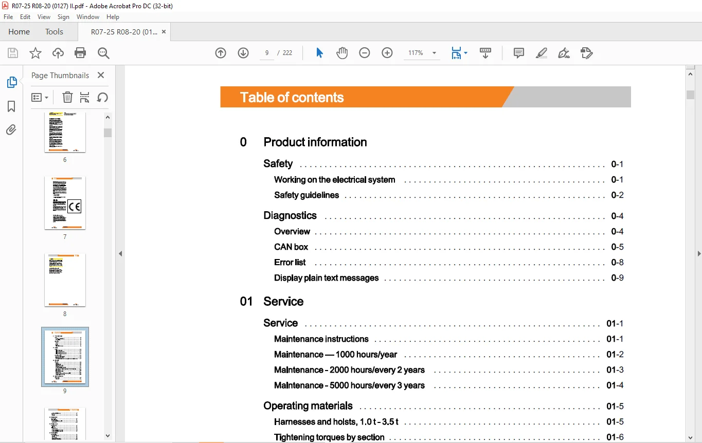
0 Product information
Safety
Working on the electrical system
Safety guidelines
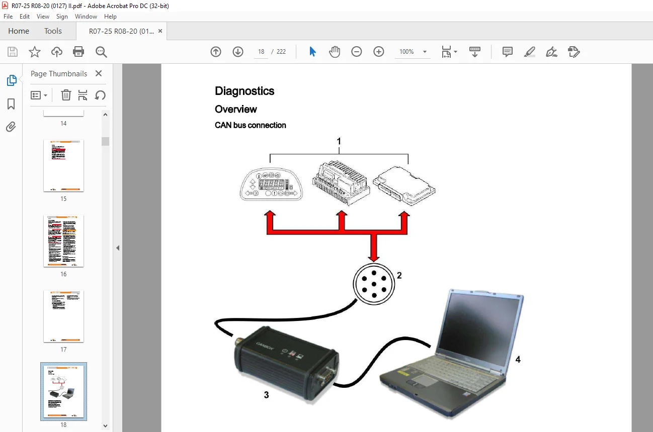
Diagnostics
Overview
CAN box
Error list
Display plain text messages
Maintenance instructions 01
Maintenance – 1000 hours/year 01
Maintenance – 2000 hours/every 2 years 01
Maintenance – 5000 hours/every 3 years 01
Operating materials 01
Harnesses and hoists, 1 0 t- 3 5 t 01
Tightening torques by section 01
Standardised tightening torques for standard-pitch threads and fine-pitch threads 01
22 Drive axle
Drive axle
Drive axle
Drive axle in detail
Drive axle wheel suspension
Drive axle – sensor system
Removing and installing the drive axle
Disassembly and assembly of the axle casing to rework the bearing seating
Engine cooling fan
Engine cooling fan in detail
Gearbox breathers
Cleaning the cooling fan and air ducts of the control unit
Draining and filling the gearbox oil
34 Driver’s compartment
Driver’s cabin
Cab in detail
Overview -1
Main brake system -4
Brake master and servo cylinders -5
Measuring wear on front brake disc -10
Front brake disc and calliper -11
Front brake pads -12
Bleeding the brakes -13
Footbrake pedal -15
Brake booster -18
Service brake cylinder / drive axle -19
Drive axle brake shoes -19
Changing the brake lining -19
-20
Electric parking brake (cycle) -20
Actuating element for the coach box brake -21
Parking brake cylinder (installation position) -22
Service brake cylinder / drive axle -23
Drive axle brake shoes -23
Changing the brake lining -23
Adjusting the parking brake -24
VIII 173709 EN – 06/2018
Table of contents
Removing and installing the cab 34
Thermostat 34
Dashboard 34
42 Steering system
Power steering 42
Front axle in detail 42
Removing and installing the front axle 42
Steering orbitrol 42
46 Wheels and tyres
Wheels and tyres 46
Winter tyres 46
Filling the tyres 46
Special removal tool 46
Removing and installing the front wheels 46
Removing and installing the drive wheels 46
49 Brake installation
Brake installation 49
Mechanical service brake 49
Table of contents
50 Controls
Accelerator 50
Accelerator pedal 50
Recuperating spring replacement 50
Preassembling the accelerator pedal 50
60 Electrics/electronics
Wiring 60
Maintenance guidelines for power cables 60
Power cables 60
Repair – Contact elements 60
Electrical control 60
EMC – Electromagnetic compatibility 60
AC Control – operating principle 60
LAC 24 (127-03) 60
Baseplate 60
Control unit for the fan housing and cooling system housing 60
LAC 24 wiring 60
Fuses 60
Fuses 127-03 60
Main contactor ( 127-03) 60
DC/DC converters 60
DC/DC converter, 80 V/13 V (127-03) 60
Lighting converters 60
Lighting relays 60
Lighting jumpers 60
Control module -A2 60
Plug connector X13 60
Switching on 60
Changed switch sequence 60
Charge resistor module -A 11 60
Electrical control – traction 60
Traction power modules 60
Seat switch 60
Battery door lock switch 60
Direction switch 60
Parking brake 60
Accelerator 60
X 173709 EN – 06/2018
Table of contents
Brake pedal switch 60
Regenerative braking 60
Improved reverse inching 60
Maintenance interval monitoring 60
Conditional compatibility 60
Coding the power characteristic curve 60
Drive axle temperature sensor 60
Temperature sensor of the drive axle (plug) 60
Inching control 60
Speed reduction switch 60
Electrical control – Steering 60
Steering power module LAC 02 ( 127-03) 60
Steering pump motor temperature sensor 60
Accumulator pressure switch 60
Electrical control – Display 60
Driver’s display 60
70 Hydraulics
Basic hydraulics 70
Hydraulic and braking system schematic 70
Pressure-controlled current regulator (PC regulator) 70
Steering orbitrol 70
Hydraulic tank breather filter replacement 70
Hydraulic fluid level check 70
Hydraulic filter replacement 70
71 Working hydraulics
Pump unit 71
Hydraulic pump 71
Pump motor 71
Pump motor in detail 71
Detailed drawing of hydraulic motor unit and pump unit 71
Connection block 71
Hydraulic motor and pump unit
Circuit diagrams
Hydraulics
Hydraulic circuit diagram
Customer Support: [email protected]
https://vimeo.com/856647044?share=copy
PLEASE NOTE:
- This is the same manual used by the dealers to diagnose and troubleshoot your vehicle
- You will be directed to the download page as soon as the purchase is completed. The whole payment and downloading process will take anywhere between 2-5 minutes
- Need any other service / repair / parts manual, please feel free to contact [email protected] . We still have 50,000 manuals unlisted
S.M