STILL STED Forklift Electric trucks RX20-14 RX20-16 RX20-18 RX20-20 workshop Manual – PDF DOWNLOAD
$28.95
STILL STED Forklift Electric trucks RX20-14 RX20-16 RX20-18 RX20-20 workshop Manual – PDF DOWNLOAD
Description
STILL STED Forklift Electric trucks RX20-14 RX20-16 RX20-18 RX20-20 workshop Manual – PDF DOWNLOAD
FILE DETAILS:
STILL STED Forklift Electric trucks RX20-14 RX20-16 RX20-18 RX20-20 workshop Manual – PDF DOWNLOAD
Language : English
Pages : 446
Downloadable : Yes
File Type : PDF
DESCRIPTION:
STILL STED Forklift Electric trucks RX20-14 RX20-16 RX20-18 RX20-20 workshop Manual – PDF DOWNLOAD
Information about the documentation
- This workshop manual contains all the information required to assist a competent person with all work, repairs and maintenance on this truck.
- For the purposes of clarity and completeness, some components have been deliberately excluded from this workshop manual and described in their own specific documentation.
- Changes may be made at short notice and at any time, and are communicated via service information documents. The documentation comprises operating instructions, additional workshop manuals, special documentation and circuit diagrams.
Operating instructions
? Original operating instructions of the truck
? Display-operating unit III
? FleetManager?
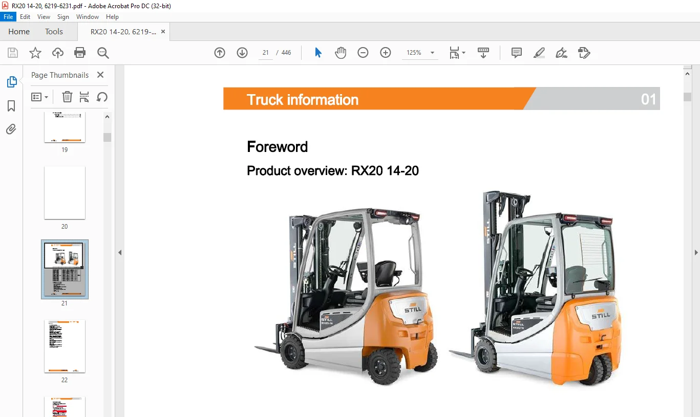
Foreword
Product overview: RX20 14-20
Special features of the series
Chassis, bodywork, interior:
Battery types A and B can be used in the
same chassis
Low entry for all chassis
Driver’s workplace with better ergonomics and
improved field of vision
Roof panels adhesively bonded
All external panelling components are made
of metal
Drive components:
Powerful drive axle AE18-11
Air-cooled converter on the drive axle
IMAGES PREVIEW OF THE MANUAL:
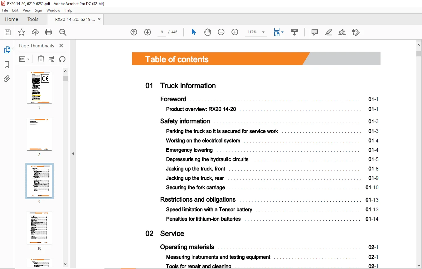
TABLE OF CONTENTS:
STILL STED Forklift Electric trucks RX20-14 RX20-16 RX20-18 RX20-20 workshop Manual – PDF DOWNLOAD
Foreword
Product overview: RX20 14-20
Safety information
Parking the truck so it is secured for service work
Working on the electrical system
Emergency lowering
Depressurising the hydraulic circuits
Jacking up the truck, front
Jacking up the truck, rear
Securing the fork carriage
Restrictions and obligations
Speed limitation with a Tensor battery
Penalties for lithium-ion batteries
02 Service
Operating materials 02
Measuring instruments and testing equipment 02
Tools for repair and cleaning 02
Special tools 02
Testing equipment for safety inspections 02
Harnesses and hoists, 1 0 t to 3 5 t 02
Standardised tightening torques for standard-pitch threads and fine-pitch threads 02
Standardised tightening torques for hose fittings 02
Introduction to DiaMon 02
Diagnostics service box 02
Diagnostic set-up 02
Working with DiaMon 02
Error list via DiaMon 02
Error ring buffer 02
Reading out access codes 02
Maintenance 03
Maintenance instructions 03
Maintenance – 1000 hours/annually 03
Maintenance – 3000 hours/every two years 03
Safety check, electrics/electronics 03
Intermediate circuit 03
Insulation testing for electric trucks 03
Component insulation testing 03
Insulation testing on the drive battery 03
Li-ion battery, checking that the battery male connector is de-energised 03
Insulation testing the lithium-ion battery 03
Test specification for the Onboard charger (OBC) 03
Test procedure for OBC 03
Safety check, hydraulics 03
Operating speeds for lowering 03
Operating speeds for lifting 03
Operating speeds for tilting 03
Forward tilt safety test 03
Lowering safety test 03
Safety checks of hose assembly 03
21 Drive components
Traction motor 21
General technical data 21
Electrical connections 21
Drive unit 21
Speed sensor 21
Temperature sensor 21
Wheel gear 21
General technical data 21
Removing the drive wheel unit 21
Changing the shaft seal on the drive wheel unit 21
Refitting the drive wheel unit 21
Table of contents
22 Axles
Mechanical drive axle 22
General technical data 22
Drive axle AE18-11 22
Traction motor – Removing the rotor 22
Traction motor – Replacing the bearing and shaft seal 22
Traction motor – Installing the rotor 22
Checking the oil level, changing the oil 22
24 Steering systems
Hydraulic steering 24
General technical data 24
Steering system 24
Steering angle sensor 3B 1 24
Priority valve 24
Steering turntable 24
General technical data 24
Functional description 24
Steering angle sensor 3B2 24
Removing/installing the steering axle 24
Combined axle 24
General technical data 24
Functional description 24
Removing/installing the steering axle 24
Adjusting the steering angle 24
Wheel hub – Replacing the bearings and sealing ring 24
Disassembling the steering cylinder and track rod 24
Replacing the axle stub, bearings and wiper 24
Steering cylinder, changing the seals 24
Steering angle sensor 3B2 24
26 Brake system
Service brake 26
Service brake AE18-11 26
Dismantling the brake 26
Assembling the brake 26
Brake clearance 26
Table of contents
Brake sensor 1 B2 26
Adjusting the service brake 26
Parking brake, mechanical 26
Brake actuation 26
Handbrake switch 1 S3 26
Adjusting the handbrake 26
Parking brake, electrical 26
Function and layout 26
Removing/installing the ELF 2 26
Changing and adjusting the brake cable 26
Zero position switch 1 S3 26
ELF 2 – Calibration 26
Brake test 26
31 Chassis and bodywork
Counterweight 31
Counterweight 31
Ballast weight 31
Overhead guard 31
Overhead guard bearings 31
Repairing the roof panels 31
Battery door 31
Battery door 31
Battery door sensor 1 S27 31
41 Interior
Hoods and panelling 41
Panels on the driver’s compartment 41
43 Operating units
Pedal groups 43
Accelerator pedal, generation 2 43
Dual pedal, generation 2 43
Table of contents
Operating devices
Drive direction selector and indicator module, generation 3
Working hydraulics controls
Hand lever
Joystick 4Plus
Mini-lever 2
Fingertip switch
44 Display elements
Display-operating unit
Display and operating unit ABE 3
Error lists via ABE 3
Parameters via ABE 3
Calibration via ABE
61 Wiring
Standard
CAN bus system
CAN bus connections
Diagnostic connector X50
Earth wires in the truck
Power
Maintenance guidelines for power cables
62 Electrics/electronics components
Electrical system
General technical data
Overview of electrical components
Switch-on process for the electrical system
Transmitters and sensors
Sensor overview for lift mast functions
Lift mast functions with lift height sensor 6B32
Tilt angle sensor 7B46
Lift height switch 7B41
Lifting stage switch 7B43
Installation positions for the lifting stage switch 7B43
Pressure sensor for lifting 7B45
Differential pressure sensors for tilting 7B4 7 and 7B48
Table of contents
LED lift height sensor 6B32 62
Aligning the LED lift height sensor 62
Installation positions for the LED lift height sensor 62
Cooling system 62
Cooling system 62
Fan 62
64 Control units
Traction controller 64
Truck control unit MCU 3 64
Removing/installing the MCU 3 64
Power distributor PDU (A5) 64
Current sensor Mini-SU (A43) 64
Contactor 1 K 1 64
Converter 64
Converter 64
Converter SAC 1 1 64
SAC-TP converter 64
Removing/installing converters 64
Auxiliary control units 64
Fuse boxA21 64
Fuses 64
CAN distributor 64
Standard CPP 64
CPP 3 (seat) 64
Optionboard (AS) 64
65 Energy supply
Voltage transformer 65
Voltage converter 65
Battery male connector 65
Battery male connector – sensor system 65
Battery male connector for lead batteries and Li-Ion Ready 65
Battery male connector for lithium-ion batteries 65
Maintenance work for appliance plugs 65
Repair – Battery male connector contacts 65
Working with reducer sleeves 65
Table of contents
Lead acid battery 65
General technical data 65
Battery 65
Lithium-ion batteries 65
Working on lithium-ion batteries 65
General technical data 65
Battery management system (BMS) 65
Diagnostics 65
Battery display 65
Battery discharge 65
Course of action for a deeply discharged battery 65
Removing/installing the battery cable 65
Battery charger 65
Onboard charger (OBC) in the truck 65
Onboard charger (A32) 65
Cooling fans 65
Fan controller 65
Charger socket in the truck 65
Wiring 65
Charging cable 65
66 Assistance system
Tilt angle-dependent functions 66
Mast tilt angle display 66
Tilt end stop damping 66
Automatic mast vertical positioning 66
Load-dependent functions 66
Load measurement and load detection 66
Dynamic Load Control 1 66
Dynamic Load Control 2 66
Lift height-dependent functions 66
Speed reduction at a lift height of 500 mm 66
Lift height display via lift height sensor 6B32 66
Electrically controlled fork wear protection 66
Lift mast end-stop damping 66
Lift transition damping 66
STILL
Table of contents
Steering angle-dependent functions 66
Steering angle-dependent driving characteristics (CSC) 66
Special functions 66
Shake function 66
67 Embedded software
Truck software 67
Overview of the controllers 67
Software compatibility 67
Parameter management 67
68 Parameterising
Assistance systems 68
Tilt angle-dependent functions 68
Load-dependent functions 68
Dynamic Load Control 68
Lift height-dependent functions with lift height sensor 6B32 68
Electrically controlled fork wear protection 68
Hydraulics 68
Axle assignment of the operating devices 68
Input characteristic curves for the operating devices 68
Speed and dynamics of the operating devices 68
71 Basic hydraulics and working hydraulics
Pump-motor unit 71
General technical data 71
Electrical connections 71
Pump-motor unit 71
Pump motor 71
Temperature sensor 71
Removing/installing the pump motor 71
Hydraulic pump 71
General technical data 71
Hydraulic pump 71
Table of contents
Accumulator 71
Accumulator 71
Checking the accumulator 71
Hydraulic oil filter 71
General technical data 71
Return line filter with breather filter 71
Oil temperature sensor 2R17 71
Intake filter 71
High-pressure filter 71
Directional control valve, multi-lever 71
General technical data 71
Basic hydraulics: Hand lever 71
Hand lever valve block 71
Removing/installing the valve block 71
Directional control valve, servo hydraulics 71
General technical data 71
Basic hydraulics: Servo hydraulics 71
Servo hydraulics valve block 71
Removing/installing the valve block 71
Hydraulic oil 71
Draining the hydraulic oil 71
Changing the hydraulic oil 71
72 Cylinders
Lift cylinder 72
Lift jack 72
Working on lift cylinders 72
Bleeding the hydraulic cylinders 72
Disassembling/assembling the outer cylinder 72
Disassembling/assembling the middle cylinder 72
End position damping, type B {bottom) 72
End position damping, type A {top) 72
Line break safety valve 72
Tilt cylinder 72
Mast tilt 72
Removing/installing the tilt cylinder 72
Changing the set of seals, 1400 2000 kg 72
Table of contents
73 Auxiliary hydraulics
Auxiliary hydraulics 73
Operating lock for attachments in accordance with ISO 3691 73
80 Lifting system
Lift mast, general 80
General technical data 80
Working on lift masts 80
Run-out stop 80
Telescopic lift mast 80
Telescopic lift mast NeMaS 80
Adjusting the load chains (108/117-NeMaS) 80
Removing/installing outer cylinders 80
Changing the support rollers in the lift mast 80
Outer load chains and chain rollers 80
NiHo lift mast 80
NiHo lift mast NeMaS 80
Adjusting the load chains (108/117-NeMaS) 80
Triplex lift mast 80
Triplex lift mast NeMaS 80
Adjusting the outer load chains ( 108/117-NeMaS) 80
Adjusting the middle load chain (108/117-NeMaS) 80
Removing/installing the middle cylinder 80
Removing/installing outer cylinders 80
Changing the support rollers in the lift mast 80
Outer load chains and chain rollers 80
Middle load chain and chain roller 80
Easy View lift mast 80
General technical data 80
Lift mast Easy View 80
Adjusting the load chains (117 Easy View) 80
Removing/installing outer cylinders 80
Changing the support rollers in the lift mast 80
Load chain and chain roller 80
Table of contents
84 Lift mast assembly parts
Chains 84
Load chains – Checking and cleaning 84
Support rollers 84
Support rollers (108) 84
Support rollers (117) 84
Mast decoupling 84
Mast bearings, 1 4 t – 2 0 t 84
86 Load support
Fork carriage 86
Fork wear protection 86
Removing/installing the fork carriage 86
Fork carriage, Easy View 86
90 Other accessories
Battery carrier 90
Battery carrier 90
Retrofitting the battery carrier
Need help? Contact: [email protected]
https://vimeo.com/856640540?share=copy
PLEASE NOTE:
- This is the same manual used by the dealers to diagnose and troubleshoot your vehicle
- You will be directed to the download page as soon as the purchase is completed. The whole payment and downloading process will take anywhere between 2-5 minutes
- Need any other service / repair / parts manual, please feel free to contact [email protected] . We still have 50,000 manuals unlisted
S.M