Trusted Business
Verified & Licensed
Virus Free Files
100% Safe Downloads
Secure Payment
SSL Protected
Instant Delivery
Available Immediately
Still STED Forklift ETL13 Workshop Manual – PDF DOWNLOAD
$27.95
Still STED Forklift ETL13 Workshop Manual – PDF DOWNLOAD
Instant PDF Download
Available immediately
Save to Your Device
Download & keep forever
Antivirus Scanned
100% virus-free
Trusted Worldwide
175,000+ customers
Description
Still STED Forklift ETL13 Workshop Manual – PDF DOWNLOAD
FILE DETAILS:
Still STED Forklift ETL13 Workshop Manual – PDF DOWNLOAD
Language : English
Pages : 537
Downloadable : Yes
File Type : PDF
DESCRIPTION:
Still STED Forklift ETL13 Workshop Manual – PDF DOWNLOAD
Foreword
This workshop manual provides specifications and describes functional characteristics of the standard truck. This provides you with a comprehensive documentation to ensure better understanding of the vehicle technology and so permit correct maintenance and repair work to be carried out. The workshop manual is always updated by supplementary sheets
Updating of workshop manuals
The industrial truck range is subject to continuous further development. This means that certain components or assemblies are exchanged or modified. To ensure that the holder of this manual always has the most up to date version of the documentation, it is important to abide by the following updating system.
IMAGES PREVIEW OF THE MANUAL:
TABLE OF CONTENTS:
Still STED Forklift ETL13 Workshop Manual – PDF DOWNLOAD
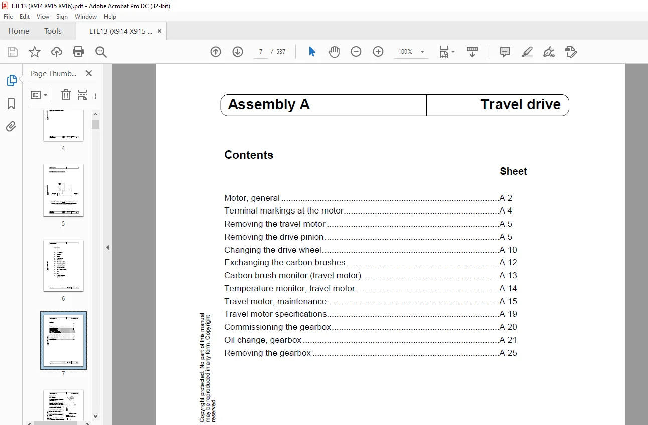
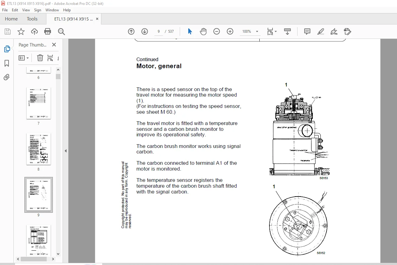
Motor, general A 2
Terminal markings at the motor A 4
Removing the travel motor A 5
Removing the drive pinion A 5
Changing the drive wheel A 10
Exchanging the carbon brushes A 12
Carbon brush monitor (travel motor) A 13
Temperature monitor, travel motor A 14
Travel motor, maintenance A 15
Travel motor specifications A 19
Commissioning the gearbox A 20
Oil change, gearbox A 21
Removing the gearbox A 25
Contents Sheet
Principle of the manual steering B2
Digital setpoint generator
– General B 3
– Pin assignment B 4
– Setting B 5
Steering controller
– Block diagram B 6
– Pin assignment B 7
– Main current terminals B 9
– Setting B 10
– Safety circuit B 13
Servo unit
– General B 15
– Exchanging the carbon brushes B 16
– Steering transmission with actual value potentiometer B 17
– Removing the servo unit B 18
– Mounting the servo unit B 19
LR80
– Allgemein B 20
– Block diagram B 24
– Position and identification numbers of the LR80 components B 25
– Steering output stage B 25 1
– Position of the central processing unit components B 26
– Position of the components on the CPU B 27/28
– Exchanging the CPU B 29
– Central processing unit
• DC/DC converter B 30
• Position of the adjusting elements on the CPU B 32
– Test operating unit B 35
– Commissioning B 40
– Fehlermeldungen B 51
– Guide frequency generator B 75
Parameteränderung mit PSION-Handprogrammiergerät B 90
Interface configuration (German software) B 91
Interface configuration (englische Software) B 93
Procedure for setting the LR80 with a PSION B 95
– Testing the mechanical elements B 96
– Physical centre of the vehicle B 97
– Adjusting the digital filter B 98
– Setting the actual value potentiometer B 100
– Maximum steering angle limit to the left B 101
– Maximum steering angle limit to the right B 102
– Testing the parameters of the calculated steering angle limits B 103
– Preadjusting the offset potentiometers B 104
– Rear/front aerial deviation B 105/106
– Testing the aerial field strength B 107
– Testing the digital setpoint generator B 108
– Setting position for straight-on travel B 109
– Optimising the parameters B 110
– Aufrufen und ändern einer Adresse B 113
– General information on storing parameters B 114
– Storing parameters in the EEPROM B 115
– Check sum error B 116
– Parameter set, version 9 08 B 117
Contact us: [email protected]
https://vimeo.com/855687477?share=copy
PLEASE NOTE:
- This is the SAME exact manual used by your dealers to fix your vehicle.
- The same can be yours in the next 2-3 mins as you will be directed to the download page immediately after paying for the manual.
- Any queries / doubts regarding your purchase, please feel free to contact [email protected]
S.M