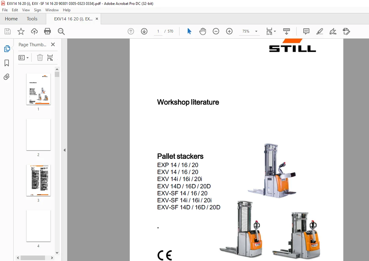
STILL STED forklift EXP 14 16 20 EXV 14 16 20 EXV 14i 16i 20i EXV 14D 16D 20D EXV-SF 14 16 20 EXV-SF 14i 16i 20i EXV-SF 14D 16D 20D Pallet stackers Workshop Manual – PDF DOWNLOAD
$30.95
STILL STED forklift EXP 14 16 20 EXV 14 16 20 EXV 14i 16i 20i EXV 14D 16D 20D EXV-SF 14 16 20 EXV-SF 14i 16i 20i EXV-SF 14D 16D 20D Pallet stackers Workshop Manual – PDF DOWNLOAD
Description
STILL STED forklift EXP 14 16 20 EXV 14 16 20 EXV 14i 16i 20i EXV 14D 16D 20D EXV-SF 14 16 20 EXV-SF 14i 16i 20i EXV-SF 14D 16D 20D Pallet stackers Workshop Manual – PDF DOWNLOAD
FILE DETAILS:
STILL STED forklift EXP 14 16 20 EXV 14 16 20 EXV 14i 16i 20i EXV 14D 16D 20D EXV-SF 14 16 20 EXV-SF 14i 16i 20i EXV-SF 14D 16D 20D Pallet stackers Workshop Manual – PDF DOWNLOAD
Language : English
Pages : 570
Downloadable : Yes
File Type : PDF
DESCRIPTION:
STILL STED forklift EXP 14 16 20 EXV 14 16 20 EXV 14i 16i 20i EXV 14D 16D 20D EXV-SF 14 16 20 EXV-SF 14i 16i 20i EXV-SF 14D 16D 20D Pallet stackers Workshop Manual – PDF DOWNLOAD
Product information – General points
Introduction
Layout
This workshop manual essentially has two parts:
? General information on the product, diagnosis
of malfunctions and special tools: Group 00
? Repair instructions: Groups 02 to 100
- Each part of the current manual is composed of a set of separate sheets that are ?led in a STILL binder according to their group number. The manual is organised according to the same rules used for the spare parts catalogue, which is divided into sub-groups (assemblies or construction groups).
- To make it as simple as possible to identify the assemblies presented in this manual, the number of each assembly is printed in the upper right-hand corner of each page. Where necessary, we have included tables to provide the maintenance department with relevant technical data.
- These tables must also be consulted by experienced mechanics. The manual contains a detailed description of truck design features, as well as component and assembly operating features. To supplement the operations described in this manual, comments, instructions and explanatory diagrams have also been provided.
IMAGES PREVIEW OF THE MANUAL:
TABLE OF CONTENTS:
STILL STED forklift EXP 14 16 20 EXV 14 16 20 EXV 14i 16i 20i EXV 14D 16D 20D EXV-SF 14 16 20 EXV-SF 14i 16i 20i EXV-SF 14D 16D 20D Pallet stackers Workshop Manual – PDF DOWNLOAD
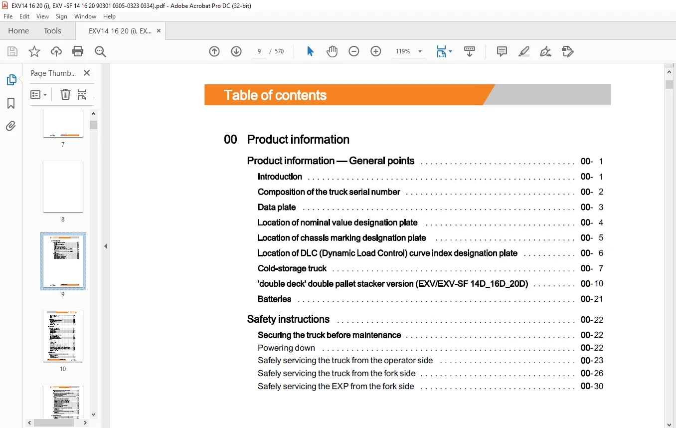
00 Product information
Product information – General points
Introduction
Composition of the truck serial number
Data plate
Location of nominal value designation plate
Location of chassis marking designation plate
Location of DLC (Dynamic Load Control) curve index designation plate
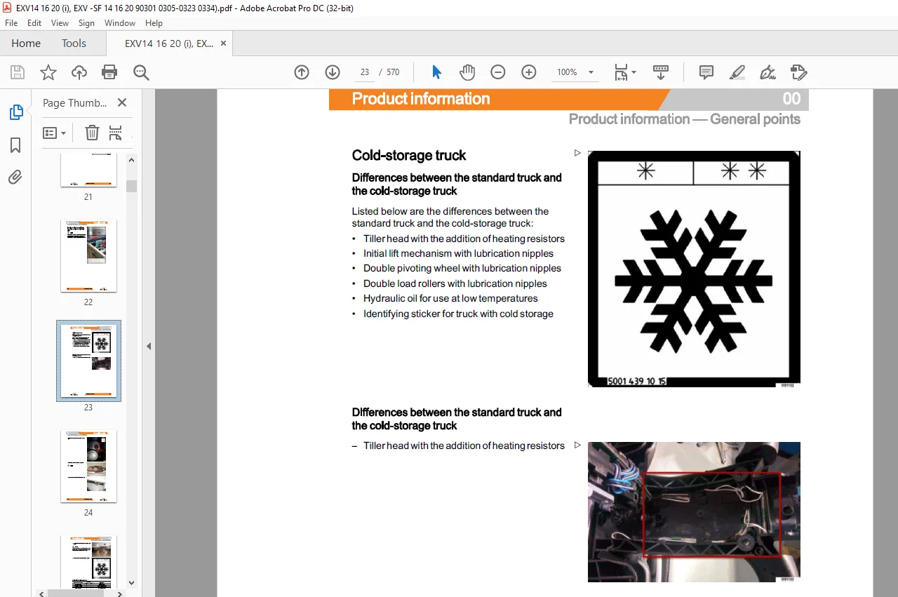
Cold-storage truck
‘double deck’ double pallet stacker version (EXV /EXV-SF 14D 16D _20D)
Batteries
Safety instructions
Securing the truck before maintenance
Powering down – 22
Safely servicing the truck from the operator side – 23
Safely servicing the truck from the fork side – 26
Emergency fork lowering 00
Loading and unloading the truck 00
Towing the truck 00
Maintenance 00
Summary Table of Maintenance Operations 00
Electrical insulation test 00
Supply table 00
Using threadlock 00
Table of tightening torques in Nm 00
02 Diagnostics
Diagnostics – General points 02
Positioning the diagnostic connector 02
CAN bus network 02
Diagnostics equipment 02
PTX File Management 02
Alarms list 02
Downloading the error list in “XPS” format 02
EXP/ EXV / EXV-SF Alarms List 02
Errors that are difficult to understand 02
List of specific alarms for a Li-Ion battery 02
Software 02
Diagnostic software 02
“Diagnosis” menu (F2) 02
“Setup” menu 02
“Measurement” menu (F4) 02
Lithium-ion battery diagnostics 02
11 Traction motor
Traction motor (for trucks produced before February 2018) 11
Traction motor exploded view 11
Technical data 11
Removing the traction motor 11
Encoder (for trucks produced before February 2018) 11
Disassembling the traction motor encoder 11
Temperature sensor (for trucks produced before February 2018) 11
Replacing the traction motor temperature sensor 11
Temperature sensor KTY84-130 11
OWD – One Wheel Drive – traction motor (for trucks produced after March
2018) 11
Exploded view of the 1 5-kW traction motor (EXP/ EXV) 11
Exploded view of the 2 3-kW traction motor (EXV-SF) 11
Technical features of the 1 5-kW traction motor (EXP/ EXV) 11
Technical features of the 2 3-kW traction motor (EXV-SF) 11
Removing the traction motor phases 11
Fitting the traction motor phases 11
Removing the cover from the traction motor phases 11
Removing the OWD traction motor 11
OWD speed sensor (for trucks produced after March 2018) 11
Technical features 11
Removing the speed sensor 1 B2 11
OWD temperature sensor (for trucks produced after March 2018) 11
Technical features 11
Removing the temperature sensor 1 B6 11
22 Reduction gear unit
Reduction gear unit (for trucks produced before February 2018) 22
Technical data 22
Changing the oil of the reduction gear unit 22
Removing the reduction gear unit 22
Disassembling internal reduction gear unit parts 22
OWD – One Wheel Drive – reduction gear unit (for trucks produced after
March 2018) 22
Exploded view of the transmission reduction gear unit (EXP/ EXV / EXV-SF) 22
Technical features of the transmission reduction gear unit (EXP/ EXV / EXV-SF) 22
Changing the reduction gear unit oil 22
Removing the transmission reduction gear unit 22
31 Truck structure
Hoods
Removing the hood – Version without platform
Removing the tiller cable ? Version with platformStandard tiller -18
Removing the gas spring ? Version with platformStandard tiller -21
Removing the tiller microswitch ? Version with platformStandard tiller -23
Removing the stop position pads ? Platform version ? Standard tiller -26
Disassembling the tiller arm ? Version with platformStandard tiller -27
-32
Removing the combi tiller covers -32
Removing the combi tiller chain -35
X 45758042102 EN – 5/2018
Removing the hood – Version with platform
Removing the hood tiller-Version with platform
Movable operator side panels
Disassembling the operator side protection panels
Removing the wiring of the side panel microswitches
Adjusting the side panel microswitch
Removing the gas spring of the operator side panels
Disassembling the support of the operator side panels
Bumper
Disassembling the bumper
Operator platform
Removing the shock absorber of the step plate
Replacing the disc springs of the operator platform
Replacing the helicoidal spring and tip
Replacing the inductive sensors of the step plate
Disassembling the operator platform
Disassembling platform subcomponents
EXP straddle gauge
Modifying the EXP straddle gauge
42 Electric steering
Tiller-Version without platform 42
Removing the tiller cable- Version without platform 42
Removing the gas spring- Version without platform 42
Disassembling the tiller arm -Version without platform 42
Removing the “Optispeed” tiller tilt potentiometer- Version without platform 42
Removing the tiller potentiometer- Version without platform 42
Tiller-Version with platform 42
Removing the tiller potentiometer- Version with platform 42
Standard tiller 42
45758042102 EN – 5/2018 XI
Table of contents
Tiller base
Tiller base
Removing the tiller base- Version without platform
Removing the tiller base-Version with platform
Steering motor unit
ES30-24
ES30-24 inputs/outputs
Electrical steering system maintenance
Removing the steering motor unit
46 Wheels
Drive wheel
Disassembling the drive wheel
Pivoting wheel
Disassembling the single pivoting wheel
Disassembling the double pivoting wheel
Disassembling the pivoting wheel – EXP
Adjusting the pivoting wheel height
Load rollers
Disassembling the single load rollers
Disassembling the double load rollers
49 Brake system
Electromagnetic brake (for trucks produced before February 2018) 49
Technical data 49
Removing the electromagnetic brake 49
Adjusting the electromagnetic brake 49
OWD-One Wheel Drive- electromagnetic brake (for trucks produced after
March 2018) 49
Technical features (brake for 1 5 kW OWD motor) 49
Technical features (brake for 2 3 kW OWD motor) 49
OWD electromagnetic brake 49
Removing the electromagnetic brake Y1 49
Checking the electromagnetic brake air gap 49
XII 45758042102 EN – 5/2018
Table of contents
50 Control elements
Tiller PCB 50
Disassembling the tiller PCB 50
56 Display elements
Display 56
Display technical features – Input/output 56
Disassembling the display 56
60 Electric and electronic components
Electric components 60
Disassembling the ignition switch – Version with platform 60
Digicode option (LFM Go) 60
Removing the contactor and emergency stop button 60
Removing the front fork carriage sensors 60
“OPTISPEED” tiller tilt potentiometer 60
Electrical connectors 60
Fuses 60
Electrical connectors 60
64 Electronic controls
LAC-03/04 electronic control 64
Technical features of the LAC03/LAC04 64
Removing the LAC03 controller 64
71 Pump unit
Pump unit 71
Pump unit technical features 71
Removing the pressure switch 71
Removing the pump unit 71
Checking and removing the pump unit brushes 71
Removing the solenoid valves 71
Removing the hydraulic pump 71
Removing the filters 71
Bleeding air from the hydraulic system 71
Replacing the solenoid valve coils 71
Table of contents
81 Lifting system
Triplex lifting mast
Removing the mast carriage
Removing and refitting the lifting mast
Assembling and disassembling the Triplex lift mast
Adjusting the lift tilt
Adjusting the tilt of the mast
Initial lift
Replacing the wiring of the initial lift inductive sensor
Removing the initial lift bearings
Adjusting the initial lift bearing clearance
Removing the initial lift cylinders
Removing the initial lift strut
EXP truck
Removing the forks – EXP
90 Optional
On-board charger
On-board charger technical features
Removing the on-board charger
DLC (Dynamic Load Control)
DLC (Dynamic Load Control)
Technical features of the ultrasonic height sensors (DLC3)
Replacing the batteries of the receiver (B)
Retrofitting ultrasonic sensors for DLC3
Annex
100 Appendix
LAC-03/04 input/output
Input/ Output LAC03
Parameters
Parameters list
Safely servicing the EXP from the fork side
Questions? Email us: [email protected]
https://vimeo.com/854988767?share=copy
PLEASE NOTE:
- This is the SAME exact manual used by your dealers to fix your vehicle.
- The same can be yours in the next 2-3 mins as you will be directed to the download page immediately after paying for the manual.
- Any queries / doubts regarding your purchase, please feel free to contact [email protected]
S.M