Still STED Forklift FV-X(12-16) FV-X(12-16)i Repair Manual PDF
$28.95
STILL STED forklift FV-X(12-16) FV-X(12-16)i Workshop Manual – PDF DOWNLOAD
Description
STILL STED forklift FV-X(12-16) FV-X(12-16)i Workshop Manual – PDF DOWNLOAD
FILE DETAILS:
STILL STED forklift FV-X(12-16) FV-X(12-16)i Workshop Manual – PDF DOWNLOAD
Language : English
Pages : 192
Downloadable : Yes
File Type : PDF
DESCRIPTION:
STILL STED forklift FV-X(12-16) FV-X(12-16)i Workshop Manual – PDF DOWNLOAD
Instruction and maintenance manual
? It is battery powered;
? The driver sits aboard the forklift.
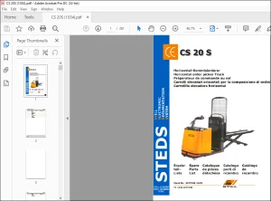
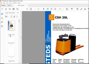
? The forklift is a stacker with supporting sidemembers and forks whose arms cover the sidemembers themselves. In addition to stacking, the version with initial spoke lifting may also be used for handling.
?.Given its construction, the forklift is used to lift, stack and arrange loads of well defined weight and volume on racks. The version with initial spoke lifting function, the forklift may also be used to handle loads of well defined weight and volume
IMAGES PREVIEW OF THE MANUAL:
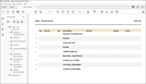
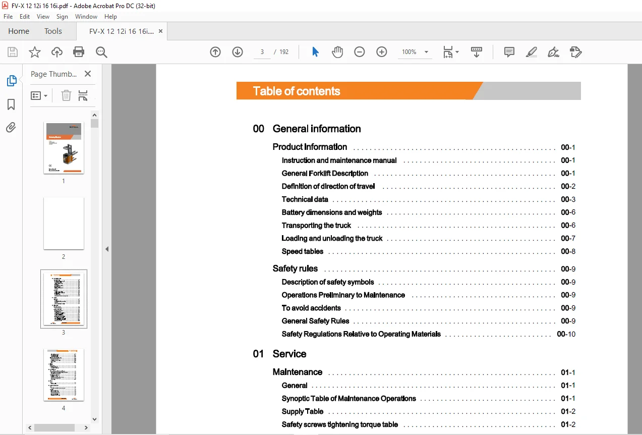
TABLE OF CONTENTS:
STILL STED forklift FV-X(12-16) FV-X(12-16)i Workshop Manual – PDF DOWNLOAD
00 General information
Product information 00
Instruction and maintenance manual 00
General Forklift Description 00
Definition of direction of travel 00
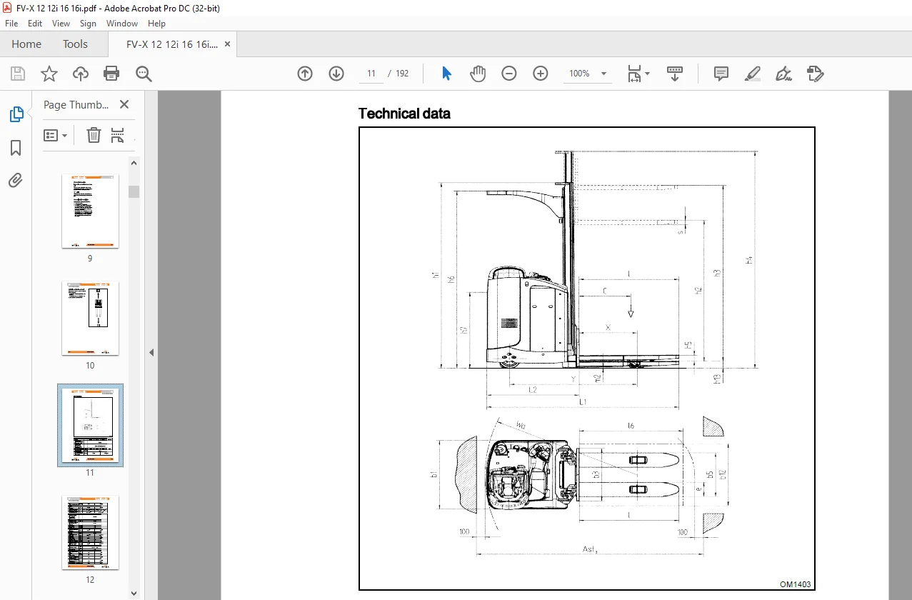
Technical data 00
Battery dimensions and weights 00
Transporting the truck 00
Loading and unloading the truck 00
Speed tables 00
Safety rules 00
Description of safety symbols 00
Operations Preliminary to Maintenance 00
To avoid accidents 00
General Safety Rules 00
Safety Regulations Relative to Operating Materials 00
01 Service
Maintenance 01
General 01
Synoptic Table of Maintenance Operations 01
Supply Table 01
Safety screws tightening torque table 01
02 Diagnostics
Diagnostic connectors 02
Connectors for diagnostics 02
Zapi system diagnostics 02
Information about the software 02
PC CONSOLE software 02
Description of the PC CONSOLE menus 02
Menu description PARAMETER 02
Description of the TESTER menu 02
Traction section parameters (MASTER) 02
Pump section parameters (SLAVE) 02
Drive section TESTER function (MASTER) 02
Pump section TESTER function (SLAVE) 02
Standard parameters table 02
Table of contents
Drive section alarms (master) 02
Pump section alarms (slave) 02
Analogue signal acquisition 02
“LES” electrical steering diagnostics 02
Diagnostics by means of PC 02
Description of the software functions 02
Parameter values 02
Alarms 02
11 Engine
Traction motor 11
Removing the drive motor 11
Reassembly of the drive motor 11
22 Reduction gear
Disassembly/reassembly of the reduction gear 22
Disassembly of the anchorage plate and drive reducer gearbox 22
Reassembly of the reducer gearbox 22
Reduction gear maintenance 22
Description of the reducer 22
Instructions for assembly/ service on the reducer 22
Adjustment of the bevel gear system 22
Reducer section 22
31 Truck
Covers 31
Internal accessibility 31
34 Driver’s compartment
Seat 34
Removal and reassembly of the seat and seat support 34
Step plate 34
Platform removal procedure 34
Platform gas spring removal 34
Platform gas spring disassembly 34
Platform gas spring refitting 34
Mobile platform structure removal 34
Table of contents
42 Steering
Electrical steering 42
Electrical steering system 42
LES activation 42
Electrical steering system calibration 42
Removal and assembly of the steering motor 42
Reassembly of the drive wheel position potentiometer 42
46 Wheels
Wheels 46
Access to the drive wheel retaining nuts 46
Wheel Tightening Check 46
Wheel Wear Check 46
Disassembly and reassembly of the traction wheel 46
49 Braking system
Braking devices and methods 49
Removal of the electromagnetic brake; 49
Service brake (eABS) 49
Description of service braking ( e-ABS) 49
Features of the eABS module 49
Alarms encoding 49
List of alarms 49
60 Electrical and electronic system
Electrical/electronic system: general information 60
COMBI AC1 electronic control functional diagram 60
CHARACTERISTICS COMBI AC1 60
COMBI AC1 inputs and outputs 60
Removal of the electric panel 60
Wiring 60
Changing a fuse 60
Power fuse installation 60
Batteries 60
Low battery charge indicator and counter 60
Battery replacement 60
Stand with lateral battery extraction roller unit (optional) 60
Electrolyte Level and Density Check 60
Table of contents
Battery Recharging 60
71 Hydraulic components
Valve group 71
Valve block for versions with initial wheel lifting 71
Valve block for versions without initial wheel lifting 71
Motor – pump – tank 71
Removal and assembly of the tank-pump-motor unit 71
80 Lifting
Lift mast 80
Lift assembly 80
Mobile structure 80
Disassembly of the mobile structure 80
Disassembly and reassembly of the lift cylinders 80
Adjustment of the guide bearings for the mobile structure 80
Replacement of the lift cylinder gaskets 80
Maintenance of the mobile structure lever systems 80
Strut length adjustment 80
Annex
A Diagrams
Wiring diagrams A
Circuit diagram (electrical connection): model with preliminary fork lifting function –
sheet 1 A
Circuit diagram (electrical connection): model with preliminary fork lifting function –
sheet2 A
Circuit diagram (electrical connection): model with preliminary fork lifting function –
sheet3 A
Circuit diagram “Cold store” ( optional): model with preliminary fork lifting function A
Circuit diagram “Fleet Manager” (optional): model with preliminary fork lifting funcb
Circuit diagram “PSL keypad/key” (optional): model with preliminary fork lifting funcb
Circuit diagram “Reversed electrical steering” ( optional): model with preliminary fork
lifting function A
Circuit diagram (electrical connection): model without preliminary fork lifting function –
sheet 1
Circuit diagram (electrical connection): model without preliminary fork lifting function –
sheet2 A
Circuit diagram (electrical connection): model without preliminary fork lifting function –
sheet3 A
Circuit diagram (electrical connection): model without preliminary fork lifting function –
sheet4 A
Circuit diagram “Fleet Manager” (optional): model without preliminary fork lifting func-
~ A
Circuit diagram “Keypad” (optional): model without preliminary fork lifting function A
Circuit diagram “Reversed steering” (optional): model without preliminary fork lifting
function A
Hydraulic diagrams A
Hydraulic connection diagram for “DPX – TPX lift masts”: model with preliminary fork
lifting function – sheet 1/2 A
Hydraulic connection diagram “SPX lift masts”: model with preliminary fork lifting function
– sheet 2/2 A
Hydraulic connection diagram “DPX – TPX lifts” model without preliminary fork lifting
function- sheet 1/2 A
Hydraulic connection diagram “SPX lift” model without preliminary fork lift function –
sheet2/2
Questions? Email us: [email protected]
https://vimeo.com/854965910?share=copy
PLEASE NOTE:
- This is the same manual used by the DEALERSHIPS to SERVICE your vehicle.
- The manual can be all yours – Once payment is complete, you will be taken to the download page from where you can download the manual. All in 2-5 minutes time!!
- Need any other service / repair / parts manual, please feel free to contact us at heydownloadss @gmail.com . We may surprise you with a nice offer
S.M