STILL STED Forklift FXD20N Double pallet stacker with driver seated Workshop Manual – PDF DOWNLOAD
$27.95
STILL STED Forklift FXD20N Double pallet stacker with driver seated Workshop Manual – PDF DOWNLOAD
Description
STILL STED Forklift FXD20N Double pallet stacker with driver seated Workshop Manual – PDF DOWNLOAD
FILE DETAILS:
STILL STED Forklift FXD20N Double pallet stacker with driver seated Workshop Manual – PDF DOWNLOAD
Language : English
Pages : 208
Downloadable : Yes
File Type : PDF
IMAGES PREVIEW OF THE MANUAL:
TABLE OF CONTENTS:
STILL STED Forklift FXD20N Double pallet stacker with driver seated Workshop Manual – PDF DOWNLOAD
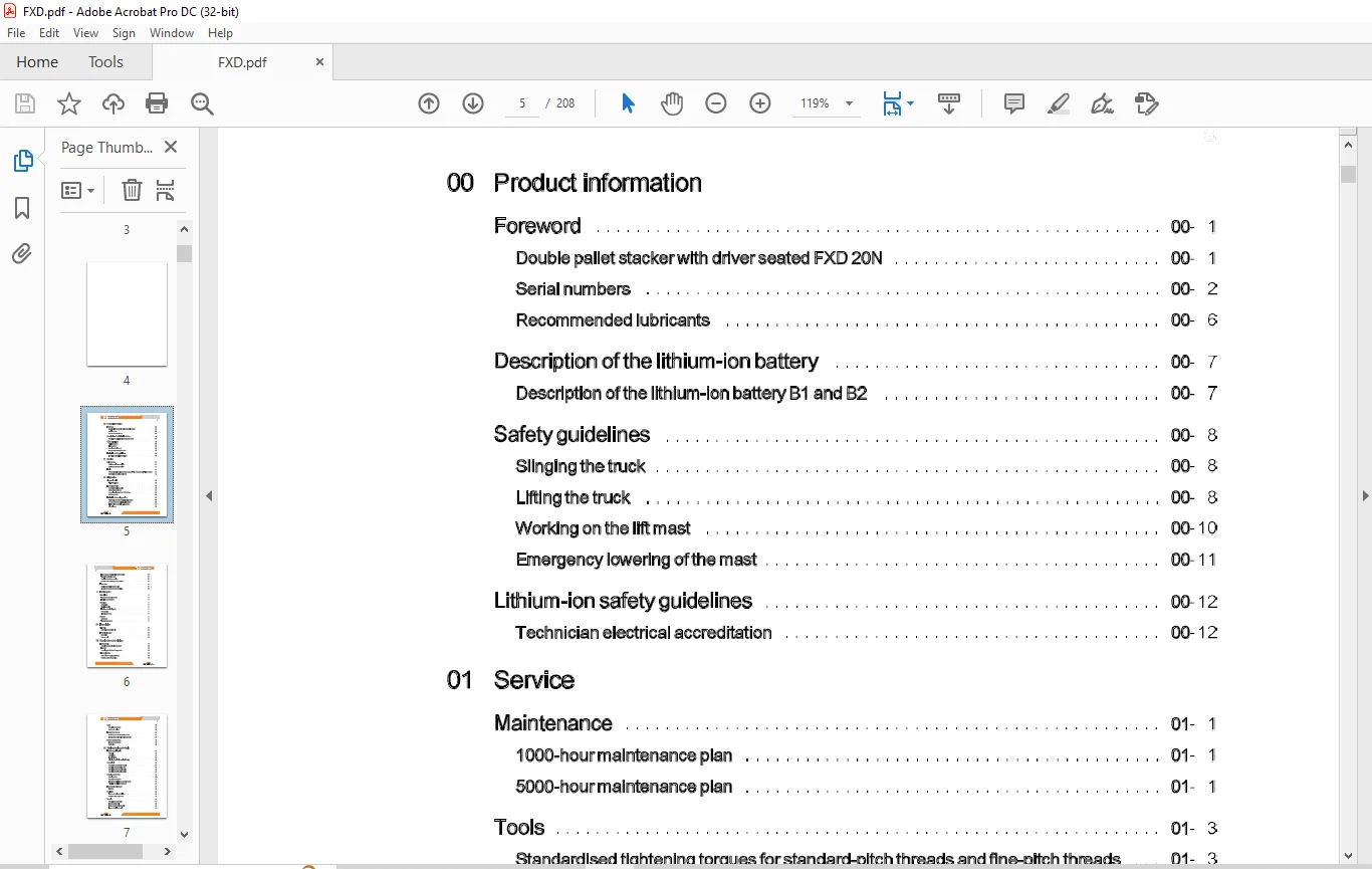
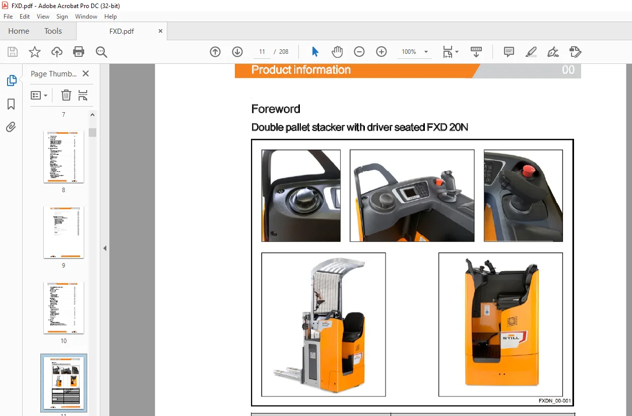
00 Product information
~~O~ – – – – – – – —
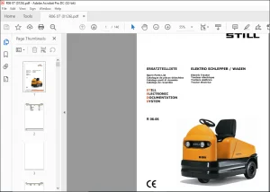
Double pallet stacker with driver seated FXD 20N _ _
Serial numbers ______ _
Recommended lubricants _ _
Description of the lithium-ion battery _____________ __ _
Description of the lithium-ion battery B1 and B2
Safety guidelines
Slinging the truck
Lifting the truck ______ _ _
Working on the lift mast
Emergency lowering of the mast
Lithium-ion safety guidelines
Technician electrical accreditation
01 Service
Maintenance
1000-hour maintenance plan
5000-hour maintenance plan
Tools 01- 3
Standardised tightening torques for standard-pitch threads and fine-pitch threads 01- 3
Measuring and testing equipment 01- 4
02 Diagnostics
Diagnostic tool
ST EDS-Navigator
Truck diagnostics
Accessingtruckinformation _ _
Diagnostics service box
Connecting a laptop to the USB CAN Box _ _
CAN bus network
Lithium-ion battery diagnostics ________________________
Diagnostic connector of the lithium-ion battery
CAN bus network of the lithium-ion battery _ _ _
Indicator lightforthe lithium-ion battery
Block diagram
STILL 11648012111 EN – 09/2017
Table of contents
Error codes for the lithium-ion battery B1-B2 02-11
Troubleshooting flow chart 02-14
Analysing the battery condition 02-25
Questionnaire to identify battery condition 02-27
Error codes 02-28
Reading and deleting the error list 02-28
Pictograms of error codes on the display 02- 30
11 Traction motor
Description 11-
Features of the traction motor 11-
Location of components 11- 3
Checking 11- 4
Preparation 11- 4
Visual inspection 11- 4
Traction motor winding test 11- 4
Rotor testing 11- 4
Cleaning the motor 11- 5
Sensors 11- 6
Rev sensor 11- 6
Temperature sensor 11- 7
23 Transmission
Drive unit 23-
Description of the drive unit 23-
Transmission gear 23- 2
Description 23- 2
Reducer unit 23- 4
30 Chassis, bodywork and fittings
IV
Fixed chassis 30-
Accessing the technical compartment 30-
Features 30- 2
Accessing the dashboard components 30- 3
Driver’s platform 30- 4
Description of the adjustable floor 30- 4
Operator presence detection 30- 5
11648012111 EN -09/2017 STILL
Table of contents
Seat 30- 6
Description of the seat 30- 6
Seat heater (option) 30- 8
Linkage of the truck 30- 9
Load lift system with level compensator 30- 9
Load lift system without level compensator 30-11
Battery compartment 30-12
Types of compartment 30-12
Battery lock 30-13
42 Steering, braking and wheels
ES30-24 steering unit 42-
General 42-
Description 42- 2
Technical data 42- 3
Adjusting the electric steering ES30-24 42- 4
Control unit 42- 6
Description of the steering wheel 42- 6
Description of the steering knob 42- 7
Description of the control module 42- 8
Descriptionofthejoystick(option) 42-10
Setpoint sensor 3B2 42-11
Steering centre 42-11
Description of the pivot 42-12
Features of the Hall effect setpoint sensor 42-13
Principle of the Hall effect sensor 42-14
Electromagnetic brake 42-15
Features 42-15
Stabiliser 42-16
Features of the fixed stabiliser 42-16
Stabiliser height adjustment 42-17
Wheels 42-19
Description of the wheels 42-19
Types of drive wheel 42-20
Types of wear on drive wheels 42- 21
Typesofstabiliserwheels 42-22
STILL 11648012111 EN – 09/2017 V
Table of contents
Typesofloadwheel 42-23
50 Control devices
Control module 50-
Traction function on the control module 50-
lnitial lift function on the control module 50- 2
Main lift function on the control module 50- 3
Horn function on the control module 50- 4
Joystick (option) 50- 5
Functions of the joystick 50- 5
60 Electrics/electronics
VI
Safety 60-
Safety guidelines for electrical equipment 60-
Cleaning the electrical system 60- 2
Insulation testing 60- 4
Electromagnetic compatibility 60- 5
General 60- 6
Technical compartment 60- 6
Location of connectors 60- 7
Fuses 60- 8
Contact switches 60-10
Emergency off switch 60-10
Horn(4H1) 60-11
Traction and lifting 60-12
Traction and lift controller 60-12
Functions of the inputs/outputs of the LAC 60-13
Activating controllers 1 A 1 and 3A 1 60-15
Speed reductions 60-17
Central negative point 60- 18
Central positive point 60-20
Parameterising the control module 60-21
Electric steering 60-22
Electric steering unit ES30-24 60-22
Functions of the “inputs/outputs” of the ES30-24 60-23
Switching on the ES30-24 unit 60-24
Operational checks 60-26
Rev sensor ( 1 B2) 60-26
11648012111 EN -09/2017 STILL
Table of contents
Checking the operation of the temperature sensor (1 B6) 60-29
Electromagnetic brake (Y 1) 60- 31
Operator presence detection 60- 32
Fan(9M1) 60-33
Controlmodule(1B1) 60-34
Lithium-ion battery B 1 and B2 60- 35
Location of connectors for the lithium-ion battery 60- 35
Replacing the cover provided 60- 36
Replacing the push button provided 60- 38
Replacing the diagnostic harness 60- 39
Replacingtheterminal block 60-40
Replacing the power cable 60- 41
BMS 60-42
Descri ption 60-42
Replacing the BMS 60-43
Module 60-45
Lith ium-ion module 60-45
Disassembling the B1 and B2 battery module 60-46
Reassembling the B1 and B2 battery module 60-49
Replacing the shunt 60-52
Power box 60- 54
Overview 60-54
Replacing the contact switch 60- 55
Replacing the fuse 60- 57
STILL 11648012111 EN – 09/2017 VII
Table of contents
Charger for lithium-ion batteries (option) 60-58
Description 60- 58
Installing the external charger 60- 61
Hydraulic controls 60- 62
Main lift operation 60- 62
Display 60- 66
Description of the display 60- 66
Display operating unit 60- 68
Operation of the display unit 60- 68
Electronic key 60- 73
Digicode LFM GO 60- 73
FleetManager™ (option) 60- 75
FleetManager description 60- 75
TDU: Access control 60- 76
FleetManager™ option 60-77
70 Hydraulics
Hydraulic system 70-
70-
70- 2
Initial Lift operation flow chart
Main Lift operation flow chart
Pump-motor unit 70- 3
Technical features 70- 3
Operating the pump-motor unit 70- 4
Identifying the solenoid valves 70- 5
Tightening torques 70- 6
Pressure sensor 70- 8
Description 70- 8
81 Lift mast
Main lift 81-
Speed limitations (lifting/lowering) 81-
Fork position detector 2B6 (0 3 m from the ground) 81- 2
Forkheightmagneticdetector2B6(1 5mfromtheground) 81- 3
Customer Support: [email protected]
https://vimeo.com/852994690?share=copy
PLEASE NOTE:
- This is the SAME MANUAL used by the dealerships to diagnose your vehicle
- No waiting for couriers / posts as this is a PDF manual and you can download it within 2 minutes time once you make the payment.
- Your payment is all safe and the delivery of the manual is INSTANT – You will be taken to the DOWNLOAD PAGE.
- So have no hesitations whatsoever and write to us about any queries you may have : heydownloadss @gmail.com
S.M