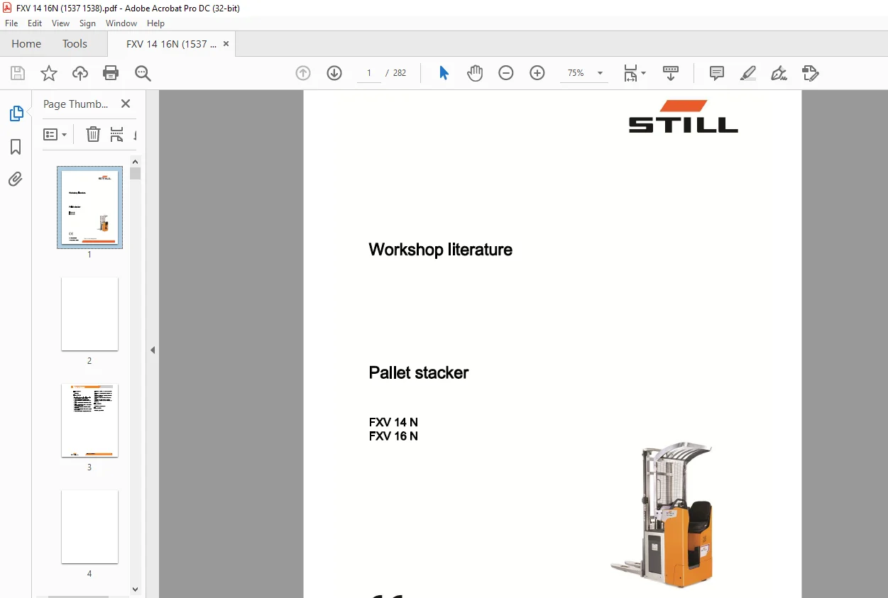
Still STED forklift FXV 14 N FXV 16 N Pallet stacker Workshop Manual – PDF DOWNLOAD
$28.95
Still STED forklift FXV 14 N FXV 16 N Pallet stacker Workshop Manual – PDF DOWNLOAD
Description
Still STED forklift FXV 14 N FXV 16 N Pallet stacker Workshop Manual – PDF DOWNLOAD
FILE DETAILS:
Still STED forklift FXV 14 N FXV 16 N Pallet stacker Workshop Manual – PDF DOWNLOAD
Language : English
Pages : 282
Downloadable : Yes
File Type : PDF
IMAGES PREVIEW OF THE MANUAL:
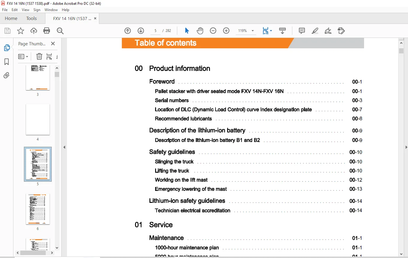
TABLE OF CONTENTS:
Still STED forklift FXV 14 N FXV 16 N Pallet stacker Workshop Manual – PDF DOWNLOAD
00 Product information
Foreword 00
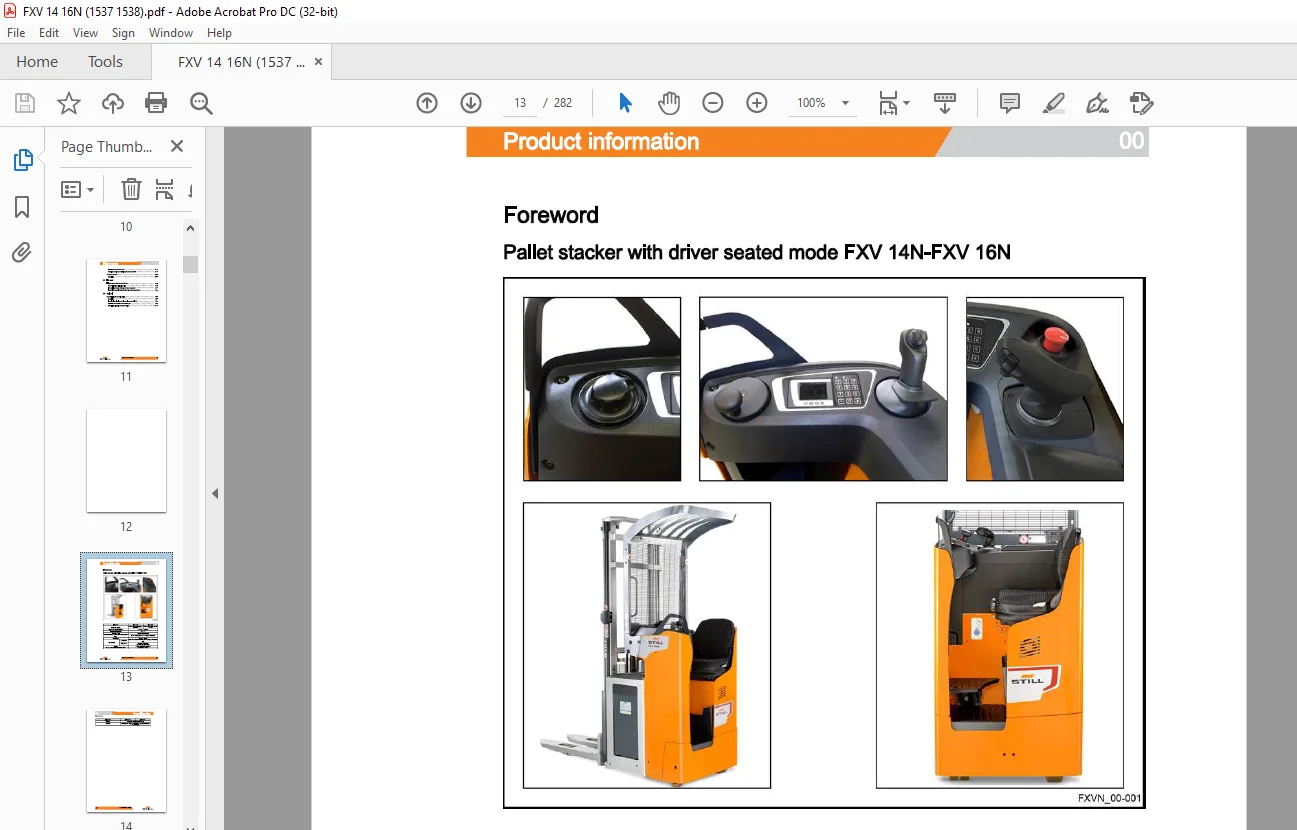
Pallet stacker with driver seated mode FXV 14N-FXV 16N 00
Serial numbers 00
Location of DLC (Dynamic Load Control) curve index designation plate 00
Recommended lubricants 00
Description of the lithium-ion battery 00
Description of the lithium-ion battery B1 and B2 00
Safety guidelines 00
Slinging the truck 00
Lifting the truck 00
Working on the lift mast 00
Emergency lowering of the mast 00
Lithium-ion safety guidelines 00
Technician electrical accreditation 00
01 Service
Maintenance 01
1000-hour maintenance plan 01
5000-hour maintenance plan 01
Maintenance schedule for lithium-ion batteries 01
Steering, braking and wheels (up to 09/2018) 01
01
Steering, braking and wheels (from 09/2018) 01
Standardised tightening torques for standard-pitch threads and fine-pitch threads 01
Tools, insulated up to 1000 V 01
Measuring and testing equipment 01
02 Diagnostic
Diagnostic tool 02
STEDS-Navigator 02
Truck diagnostics 02
Accessing truck information 02
Diagnostics service box 02
Table of contents
Connecting a laptop to the USB CAN Box 02
CAN bus network 02
Lithium-ion battery diagnostics 02
Diagnostic connector of the lithium-ion battery 02
CAN bus network of the lithium-ion battery 02
Indicator light for the lithium-ion battery 02
Block diagram 02
Error codes for the lithium-ion battery B1-B2 02
Troubleshooting flow chart 02
Analysing the battery condition 02
Questionnaire to identify battery condition 02
Error codes 02
Reading and deleting the error list 02
Pictograms of error codes on the display 02
11 Traction motor
Description up to 09/2018 11
Features of the traction motor 11
Location of components 11
Description from 09/2018 11
Features of the traction motor 11
Location of components 11
Check 11
Preparation 11
Visual inspection 11
Traction motor winding test 11
Rotor testing 11
Cleaning the motor 11
Sensors up to 09/2018 11
Rev sensor 11
Temperature sensor 11
Sensors from 09/2018 11
Rev sensor 11
Temperature sensor 11
Table of contents
23 Transmission
Drive unit 23
Description of the drive unit 23
Transmission gear up to 09/2018 23
Description 23
Reducer unit 23
Transmission gear from 09/2018 23
Description 23
Transmission gear unit 23
30 Chassis, bodywork and fittings
Fixed chassis 30
Accessing the technical compartment 30
Accessing the dashboard components 30
Driver’s platform 30
Description of the adjustable floor 30
Operator presence detection 30
Linkage of the truck 30
Load lift system with level compensator 30
Load lift system without level compensator 30
Battery compartment 30
Types of compartment 30
Battery lock 30
42 Steering, braking and wheels
Steering unit ES30-24 42
General 42
Description 42
Technical data 42
Control unit 42
Description of the steering wheel 42
Description of the steering knob 42
Description of the control module 42
Description of the joystick (option) 4
Table of contents
Setpoint sensor 3B2 42
Steering centre 42
Description of the pivot 42
Features of the Hall effect setpoint sensor 42
Principle of the Hall effect sensor 42
Electromagnetic brake up to 09/2018 42
Features 42
Electromagnetic brake from 09/2018 42
Features 42
Stabiliser 42
Features of the fixed stabiliser 42
Stabiliser height adjustment 42
Wheels 42
Description of the wheels 42
Types of drive wheel 42
Types of wear on drive wheels 42
Types of stabiliser wheels 42
Types of load wheel 42
50 Control devices
Control module 50
Traction function on the control module 50
Main lift function on the control module 50
Hom function on the control module 50
Joystick (option) 50
Functions of the joystick 50
60 Electrics/electronics
Safety 60
Safety guidelines for electrical equipment 60
Cleaning the electrical system 60
Insulation testing 60
Electromagnetic compatibility 60
General 60
Technical compartment (up to 09/2018) 60
Location of the connectors (until 09/2018) 60
Technical compartment (from 09/2018) 60
Checking the operation of the temperature sensor (1B6) -29
Electromagnetic brake (Y1) -31
Operator presence detection -32
Fan (9M1) -33
Control module (1B1) -34
Rev sensor (1B2) -35
Temperature sensor (1B6) -38
Electromagnetic brake (Y1) -4
Description -55
Replacing the BMS -56
11748012101 EN – 01/2020 VII
Table of contents
Location of connectors (from 09/2018)
Fuses
Contact switches
Emergency off switch
Horn (4H1)
Traction and lifting
Traction and lift controller
Functions of the inputs-outputs of the LAC (up to 09/2018)
Functions of the inputs-outputs of the LAC (from 09/2018)
Activating controllers 1A1 and 3A1
Speed reductions
Central negative point
Central positive point
Operational checks up to 09/2018
Operational checks from 09/2018
Electric steering
Electric steering unit ES30-24
Functions of the “inputs/outputs” of the ES30-24
Switching on the ES30-24 unit
Lithium-ion battery B 1 and B2
Location of connectors for the lithium-ion battery
Replacing the cover provided
Replacing the push button provided
Replacing the diagnostic harness
Replacing the terminal block
Replacing the power cable
Lithium-ion module -58
Disassembling the B1 and B2 battery module -59
Reassembling the B1 and B2 battery module -62
Replacing the shunt -66
-68
Overview -68
Replacing the contact switch -69
Replacing the fuse -71
Charger for lithium-ion batteries (option) 60
Description 60
Working on the external charger 60
Installing the external charger 60
Side socket on lithium-ion battery 60
Hydraulic controls 60
Main lift operation 60
Display 60
Description of the display 60
Display operating unit 60
Operation of the display unit 60
Electronic key 60
Digicode LFM GO 60
FleetManager (option) 60
FleetManager description 60
TDU: Access control 60
FleetManager™ option 60
70 Hydraulics
Hydraulic system 70
Description 70
Main Lift operation flow chart 70
Initial Lift operation flow chart 70
Operational logic of the booster 70
Pump-motor unit 70
Operation of the pump-motor unit 70
Identifying the solenoid valves 70
Technical characteristics of pump-motor units 70
Tightening torques of the pump-motor units 70
Table of contents
Bleeding the pump-motor unit 70
Changing the filter and adjusting the pressure cut-off 70
Pressure sensor 70
Description 70
81 Lift mast
Height sensor (0 3 m and 1 5 m) 81
Speed limitations (lifting/lowering) 81
Fork position detector 2B6 (0 3 m from the ground) 81
Fork height magnetic detector 2B6 (1 5 m from the ground) 81
90 Optional
Dynamic Load Control (DLC) 90
Description 90
Technical specifications for ultrasonic sensors (DLC 3) 90
Replacing the batteries of the receiver (B) 90
Retrofitting ultrasonic sensors for DLC3
Customer Support: [email protected]
https://vimeo.com/856299028?share=copy
PLEASE NOTE:
- This is the SAME exact manual used by your dealers to fix your vehicle.
- The same can be yours in the next 2-3 mins as you will be directed to the download page immediately after paying for the manual.
- Any queries / doubts regarding your purchase, please feel free to contact [email protected]
S.M