Trusted Business
Verified & Licensed
Virus Free Files
100% Safe Downloads
Secure Payment
SSL Protected
Instant Delivery
Available Immediately
STILL STED Forklift Pallet stacker EXV 14-16-20 EXV-SF 14-16-20 EXV 14-16-20 i EXV-SF 14-16-20 i EXP 14-16-20 workshop Manual – PDF DOWNLOAD
$16.95
STILL STED Forklift Pallet stacker EXV 14-16-20 EXV-SF 14-16-20 EXV 14-16-20 i EXV-SF 14-16-20 i EXP 14-16-20 workshop Manual – PDF DOWNLOAD
Instant PDF Download
Available immediately
Save to Your Device
Download & keep forever
Antivirus Scanned
100% virus-free
Trusted Worldwide
175,000+ customers
Description
STILL STED Forklift Pallet stacker EXV 14-16-20 EXV-SF 14-16-20 EXV 14-16-20 i EXV-SF 14-16-20 i EXP 14-16-20 workshop Manual – PDF DOWNLOAD
FILE DETAILS:
STILL STED Forklift Pallet stacker EXV 14-16-20 EXV-SF 14-16-20 EXV 14-16-20 i EXV-SF 14-16-20 i EXP 14-16-20 workshop Manual – PDF DOWNLOAD
Language : English
Pages : 47
Downloadable : Yes
File Type : PDF
TABLE OF CONTENTS:
STILL STED Forklift Pallet stacker EXV 14-16-20 EXV-SF 14-16-20 EXV 14-16-20 i EXV-SF 14-16-20 i EXP 14-16-20 workshop Manual – PDF DOWNLOAD
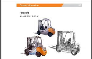
00 Product information
Product information — Generalpoints 00- 1
Introduction 00- 1
Composition of the truck serialnumber 00- 2
Chassisframelabelling 00- 4
Cold-storage truck 00- 5
Batteries 00- 8
Introduction 00- 1
Composition of the truck serialnumber 00- 2
Chassisframelabelling 00- 4
Cold-storage truck 00- 5
Batteries 00- 8
Safetyinstructions 00- 9
Securing the truck before maintenance 00- 9
Powering down 00- 9
Safely servicing the truck fromthe operatorside 00-10
Safely servicing the truck fromthe forkside 00-13
Safely servicing the EXP fromthe forkside 00-17
Emergency forklowering 00-19
Loadingandunloadingthetruck 00-20
Towingthetruck 00-21
Securing the truck before maintenance 00- 9
Powering down 00- 9
Safely servicing the truck fromthe operatorside 00-10
Safely servicing the truck fromthe forkside 00-13
Safely servicing the EXP fromthe forkside 00-17
Emergency forklowering 00-19
Loadingandunloadingthetruck 00-20
Towingthetruck 00-21
Maintenance 00-23
Summary Table of Maintenance Operations 00-23
Electrical insulationtest 00-24
Supplyfable 00-26
Usingthreadlock 00-27
Table oftighteningtorquesinNm 00-28
Summary Table of Maintenance Operations 00-23
Electrical insulationtest 00-24
Supplyfable 00-26
Usingthreadlock 00-27
Table oftighteningtorquesinNm 00-28
02 Diagnostics
Diagnostics —Generalpoints 02- 1
Positioning the diagnosticconnector L 02- 1
CANDbUS NetWork 02- 2
Diagnosticsequipment 02- 4
PTXFilelManagement 02- 5
Positioning the diagnosticconnector L 02- 1
CANDbUS NetWork 02- 2
Diagnosticsequipment 02- 4
PTXFilelManagement 02- 5
Alarms list 02- 7
Downloading the errorlistin “XPS”format 02- 7
Listofalarms 02-10
Errors thatare difficulttounderstand ool 02-31
Downloading the errorlistin “XPS”format 02- 7
Listofalarms 02-10
Errors thatare difficulttounderstand ool 02-31
Software 02-32
Diagnosticsoftware 02-32
“Diagnosis” menu (F2) 02-34
“SetUP MENU 02-45
“Setup” menu (F3) oo 02-45
Diagnosticsoftware 02-32
“Diagnosis” menu (F2) 02-34
“SetUP MENU 02-45
“Setup” menu (F3) oo 02-45
y 4
STILL
Table of contents
Truck options – General –> Truck Option i 02-45
Electronic controls – General –> Controller 02-46
Tiller potentiometer – Function –> Traction –> Tillerfoot 02-47
Speed reduction on curves – Function –> Traction –> Curve speed reduction 02-49
Battery charge level indicator – Function –> BDI –> Curve speed reduction 02-50
“Measurement’menu(F4) 02-52
11 Traction motor
Traction motor 11-1
Tractionmotorexplodedview i 11-1
Technicaldata 11-1
Removing the tractionmotor 11- 2
Tractionmotorexplodedview i 11-1
Technicaldata 11-1
Removing the tractionmotor 11- 2
Encoder 11-5
Disassembling the traction motorencoder 11- 5
Disassembling the traction motorencoder 11- 5
Temperature SENSO 1-7
Replacing the traction motor temperaturesensor 11-7
Temperature SBNSOT «oot 11-10
Replacing the traction motor temperaturesensor 11-7
Temperature SBNSOT «oot 11-10
22 Reduction gear unit
Reductiongearunit 22-1
Technicaldata 22- 1
Removing the reductiongearunit 22- 2
Changing the oil ofthe reductiongearunit 22- 5
Disassembling internal reduction gearunitparts 22-7
Technicaldata 22- 1
Removing the reductiongearunit 22- 2
Changing the oil ofthe reductiongearunit 22- 5
Disassembling internal reduction gearunitparts 22-7
31 Truck structure
Hoods 31-1
Removing the hood — Version withoutplatform 31-1
Removing the hood — Version with platform 31-5
Removing the hood tiller — Version with platform 31-8
Removing the hood — Version withoutplatform 31-1
Removing the hood — Version with platform 31-5
Removing the hood tiller — Version with platform 31-8
Movable operatorsidepanels 31-10
Disassembling the operator side protectionpanels 31-10
Removing the wiring of the side panel microswitches 31-13
Adjusting the side panel microswitch 31-16
Removing the gas spring of the operatorsidepanels 31-18
Disassembling the supportof the operatorsidepanels 31-20
Operatorplatform 31-29
Removing the shock absorberofthestepplate 31-29
Replacing the disc springs of the operatorplatiorm 31-34
Replacing the helicoidal springandtip 31-37
Replacing the inductive sensors of the stepplate 31-41
Disassembling the operatorplatform 31-44
Disassembling platform subcomponents LL 31-46
EXPstraddlegauge 31-51
Modifying the EXP straddlegauge iii 31-51
Modifying the EXP straddlegauge iii 31-51
42 Electric steering
Tiller— Versionwithoutplatform 42- 1
Removing the tiller cable — Version withoutplatiorm 42- 1
Removing the gas spring — Version withoutplatform 42- 5
Disassembling the tiller arm — Version without platform 42- 8
Removing the “Optispeed” tiller tilt potentiometer — Version without platform 42-11
Removing the tiller potentiometer — Version withoutplatform 42-13
Tiller—Versionwith platform 42-15
Removing the tiller potentiometer — Version with platform 42-15
Standardftiller 42-17
Removing the tiller cable — Version with platformStandard tiller 42-17
Removing the gas spring — Version with platformStandard tiller 42-20
Removing the tiller microswitch — Version with platformStandard tiller 42-22
Removing the stop position pads — Platform version — Standard tiller 42-25
Disassembling the tiller arm — Version with platformStandard tiller 42-26
Combitiller 42-31
Removing the combitillercovers 42-31
Removing the combitillerchain 42-34
Removing the combitillerwiring 42-36
Removing the gas springs —Combitiller 42-38
Removing the microswitches — Combitiller 42-44
Disassembling the combitiller 42-49
Tillerbase 42-51
Tillerbase 42-51
Removing the tiller base — Version withoutplatiorm 42-51
Removing the tiller base — Version with platform 42-53
Steeringmotorunit 42-55
Technicaldata 42-55
Electrical steering systemmaintenance os 42-57
STILL AEE
Table of contents
Removing the steeringmotorunit 42-58
46 Wheels
Drivewheel 46- 1
Disassemblingthedrivewheel 46- 1
Pivotingwheel 46- 3
Disassembling the single pivotingwheel 46- 3
Disassembling the double pivotingwheel 46- 5
Disassembling the pivotingwheel -EXP 46- 7
Adjusting the pivotingwheelheight 46- 9
Loadrollers 46-11
Disassembling the single loadrollers 46-11
Disassembling the double loadrollers 46-14
49 Brake system
Electromagneticbrake 49- 1
Technicaldata 49- 1
Removing the electromagneficbrake 49- 2
Adjusting the electromagneticbrake 49- 6
50 Control elements
Tiller PCB «oe 50- 1
Disassembling the fillerPCB 50- 1
56 Display elements
Display 56- 1
Display technical features — Input/output 56- 1
Disassembling thedisplay 56- 3
60 Electric and electronic components
Electriccomponents 60- 1
Disassembling the ignition switch — Version with platform 60- 1
Digicode option (LFM Go) 60- 2
Removing the contactor and emergency stopbutton 60- 4
Removing the front fork carriagesensors 60- 7
“OPTISPEED” tiller tilt potentiometer 60-10
Electricalconnectors 60-13
FUSES 60-13
Table of contents
Electricalconnectors 60-14
64 Electronic controls
LACO3 electroniccontroller ll 64- 1
LACO3technicalfeatures 64- 1
Removing the LACO3 controller 64- 3
71 Pump unit
Pumpunit 71-1
Pump unittechnicalfeatures 71-1
Removing the pressureswitch 71- 3
Removing thepumpunit 71- 5
Checking and removing the pump unitbrushes 71- 8
Removing the solenoidvalves 71-10
Removing the hydraulicpump 71-14
Removing thefilters 71-18
Bleeding air from the hydraulicsystem 71-20
Replacing the solenoid valve coils 71-23
81 Lifting system
Triplex lifingmast 81- 1
Removing the mastcarriage i 81- 1
Removing and refitting the lifingmast 81- 3
Assembling and disassembling the Triplexliftmast 81- 6
Adjusting thelifttilt 81-21
Adjusting the tiltofthemast 81-21
Initial lift 81-24
Replacing the wiring of the initial liftinductive sensor 81-24
Removing the inifial liftbearings oo 81-27
Adjusting the initial liftbearing clearance 81-31
Removing the initial liftcylinders 81-34
Removing the inifial liftstrut 81-38
EXPIrUCK 81-44
Removing theforks-EXP 81-44
90 Optional
On-boardcharger i 90- 1
On-board charger technicalfeatures 80- 1
Removing the on-boardcharger iii, 90- 3
Annex
100 Appendix
LACO3 input/output 100- 1
Input/Output LACO3 100- 1
Parameters 100- 3
Parameterslist 100- 3
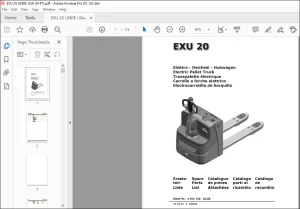
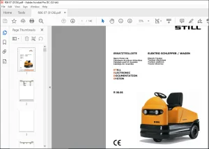
IMAGES PREVIEW OF THE MANUAL:
PLEASE NOTE:
- This is the same manual used by the dealers to diagnose and troubleshoot your vehicle
- You will be directed to the download page as soon as the purchase is completed. The whole payment and downloading process will take anywhere between 2-5 minutes
- Need any other service / repair / parts manual, please feel free to contact [email protected] . We still have 50,000 manuals unlisted
s.m