STILL STED Forklift Pallet truck with auxiliary lift EXU-H 18 EXU-H 20 workshop Manual – PDF DOWNLOAD
$28.95
STILL STED Forklift Pallet truck with auxiliary lift EXU-H 18 EXU-H 20 workshop Manual – PDF DOWNLOAD
Description
STILL STED Forklift Pallet truck with auxiliary lift EXU-H 18 EXU-H 20 workshop Manual -PDF DOWNLOAD
FILE DETAILS:
STILL STED Forklift Pallet truck with auxiliary lift EXU-H 18 EXU-H 20 workshop Manual – PDF DOWNLOAD
Language : English
Pages :276
Downloadable : Yes
File Type : PDF
IMAGES PREVIEW OF THE MANUAL:
DESCRIPTION:
STILL STED Forklift Pallet truck with auxiliary lift EXU-H 18 EXU-H 20 workshop Manual – PDF DOWNLOAD
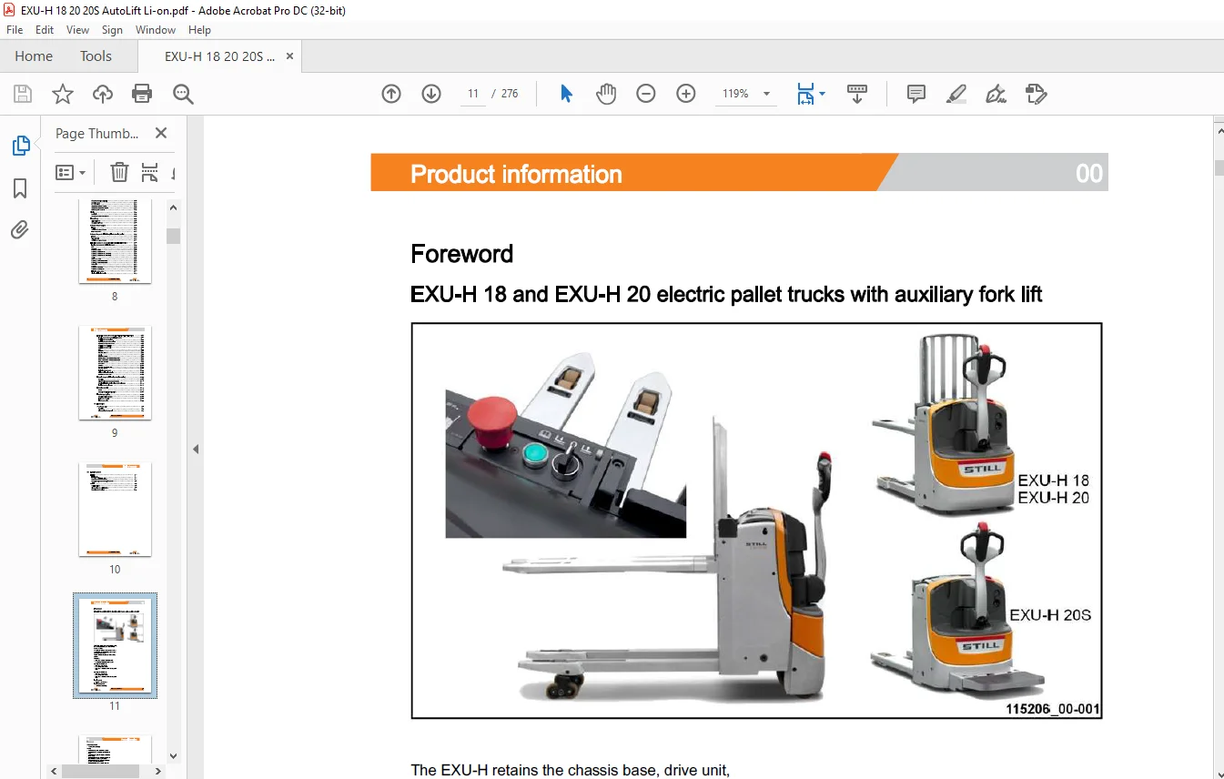
Foreword
EXU-H 18 and EXU-H 20 electric pallet trucks with auxiliary fork lift
The EXU-H retains the chassis base, drive unit, control tiller, stabilisers, LAC controller and hoods of the EXU. It is equipped with an additional mast to allow the pallet to be levelled, limiting incorrect posture during load handling. The “S” versions are equipped with a folding platform
? Load arms: 210 mm from the ground
? Fork (mast): 760 mm from the ground
Capacity of the EXU-H 18:
? Load arms only: 1800 kg
? Fork carriage only: 800 kg
? Load arms + additional mast: 1800 kg maximum
Capacity of the EXU-H 20:
? Load arms only: 2000 kg
? Fork carriage only: 800 kg
? Load arms + additional mast: 2000 kg maximum
TABLE OF CONTENTS:
STILL STED Forklift Pallet truck with auxiliary lift EXU-H 18 EXU-H 20 workshop Manual – PDF DOWNLOAD
00 Product information
Foreword
EXU-H 18 and EXU-H 20 electric pallet trucks with auxiliary fork lift
Description of the lithium-ion battery
Description of the lithium-ion battery A 1 and A2
Description of the lithium-ion battery B1 and B2
Lithium-ion safety guidelines
Technician electrical accreditation
Maintenance 01
1000-hour/annual maintenance plan 01
3000-hour maintenance plan 01
Tools 01
Standardised tightening torques for standard-pitch threads and fine-pitch threads 01
Measuring and testing equipment 01
02 Diagnostic
Diagnostic tool
STEDS-Navigator
Truck diagnostics
Accessing truck information
Diagnostics service box
Connecting a laptop to the USB CAN Box
CAN bus network
Lithium-ion battery diagnostics
Diagnostic connector of the Lithium-Ion battery
CAN bus network of the lithium-ion battery
Block diagram
Indicator light for the lithium-ion battery
Battery A 1 and A2
Lithium-ion service base -11
Error codes for the lithium-ion battery A1-A2 -12
Troubleshooting flow chart
Battery B 1 and B
Error codes for the lithium-ion battery B1-B2 -27
Analysing the battery condition 02
Questionnaire to identify battery condition 02
Error codes 02
Reading and deleting the error list 02
Pictograms of error codes on the display 02
Fault codes 02
11 Traction motor
Description 11
Features of the traction motor 11
Power module connections 11
Removing the traction motor 11
Sensors 11
Rev sensor 11
Temperature sensor 11
23 Transmission
Drive unit 23
Description of the drive unit 23
Removing the drive unit 23
Transmission gear 23
Transmission gear 23
Reducer unit 23
Removing the transmission gear 23
Changing the transmission gear seals 23
Draining the transmission gear 23
30 Truck structure
Covers 30
Access to the technical compartment 30
Driver’s platform (option) 30
Overview 30
Removing the platform 30
Battery compartment 30
Types of compartment 30
Battery lock 30
Table of contents
42 Steering, braking and wheels
Tiller 42
General 42
1 B7 tiller foot potentiometer 42
Cold-storage room version 42
Removing the tiller head 42
Gas damper 42
Removing the tiller arm 42
Electromagnetic brake 42
Electromagnetic parking brake Y1 42
Stabilisers 42
Stabilisers (standard) 42
Stabilisers (option) 42
Adjusting the height of the stabiliser wheel 42
Wheels 42
Description of the wheels 42
Types of drive wheel 42
Types of stabiliser wheels 42
Types of load wheel 42
Removing the drive wheel 42
Removing the stabiliser wheels 42
Removing the load arm components 42
60 Electrical equipment
Safety 60
Safety guidelines for electrical equipment 60
Cleaning the electrical system 60
Insulation testing 60
Electromagnetic compatibility 60
General 60
Functions of EXU-H trucks equipped with LAC 02 60
General 60
Electrical components mounting plate 60
Traction 60
Traction and hydraulic controller – LAC 02/ 1A1 60
Functions of the “Inputs/Outputs” of the LAC 02 60
Activation of the 1 A 1 controller 60
Rev sensor (1B2) -22
Temperature sensor KTY (1B6) -26
Temperature sensor PT1000 (1B6) -30
Electromagnetic brake (Y1) -33
Description -58
Replacing the BMS -60
Replacing the BMU harness -62
Replacing the SMU harness (A1 battery) -63
Replacing the SMU harness (A2 battery)
Lithium-ion module -67
Replacing the A1 battery module -68
Replacing the A2 battery module -7
Overview -72
Replacing the contactor -74
Replacing the battery fuse -75
VI 11528012006 EN – 01/2020
Table of contents
Speed reductions
Creep Speed function (optional)
Operation checks
Display
Description
Changing the multifunction indicator
Electronic key
Digicode LFM GO
Changing the LFM box
On-board charger (option)
Features
Adjusting the on-board charger
Help for diagnostics
On-board charger for lithium-ion/gel/lead batteries (option)
Features
Diagnostic help
Adjusting the on-board charger
Lithium-ion battery A 1 and A2 (EXU-H 20 ion – EXU-H 20S ion)
Location of connectors for the lithium-ion battery
BMS
Module
Power plate
Lithium-ion battery socket
Display for lithium-ion batteries
Description -87
Replacing the BMS -90
Lithium-ion module -90
Disassembling the B1 and B2 battery module -91
Reassembling the B1 and B2 battery module -94
Replacing the shunt -100
Overview -100
Replacing the contact switch -102
Replacing the fuse -104
Table of contents
Lithium-ion battery B1 and B2 (EXU-H 20 ion – EXU-H 20S ion)
Location of connectors for the lithium-ion battery
Replacing the cover provided
Replacing the push button provided
Replacing the diagnostic harness
Replacing the terminal block
Replacing the power cable
BMS
Module
Power plate
Lithium-ion battery socket
Display for lithium-ion batteries
Replacing the power cable
External charger for lithium-ion batteries (option)
Description
Using the side socket to charge the battery
Charging lithium-ion batteries using an external charger
Installing the external charger
Hydraulics controls
EXU-H
Automatic fork lifting/lowering option
FleetManager (option)
Description of Fleet Manager
TDU: Access control
FleetManager option
70 Hydraulics
Pump-motor unit
Description
Disassembling the pump unit
Table of contents
81 Load lift system
Initial lift 81
Initial lift cylinder 81
Removing the Initial Lift cylinder 81
Removing the lift shaft assembly + push rods 81
Main lift 81
Main Lift Cylinder 81
Disassembling the main lift cylinder 81
Removing the fork carriage
Troubleshooting flow chart
Contact us: [email protected]
https://vimeo.com/856141151?share=copy
PLEASE NOTE:
- This is not a physical manual but a digital manual – meaning no physical copy will be couriered to you. The manual can be yours in the next 2 mins as once you make the payment, you will be directed to the download page IMMEDIATELY.
- This is the same manual used by the dealers inorder to diagnose your vehicle of its faults.
- Require some other service manual or have any queries: please WRITE to us at [email protected]
S.M