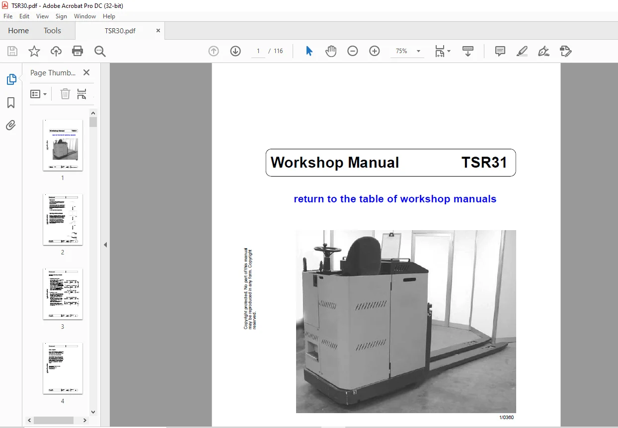
Still STED TSR31 Forklift Repair Manual PDF Download
$26.95
Still STED Forklift TSR31 Workshop Manual – PDF DOWNLOAD
Description
Still STED Forklift TSR31 Workshop Manual – PDF DOWNLOAD
FILE DETAILS:
Still STED Forklift TSR31 Workshop Manual – PDF DOWNLOAD
Language : English
Pages : 116
Downloadable : Yes
File Type : PDF
DESCRIPTION:
Still STED Forklift TSR31 Workshop Manual – PDF DOWNLOAD
Foreword
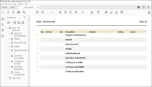
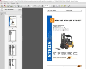
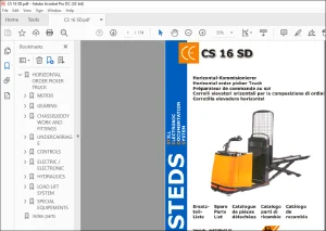
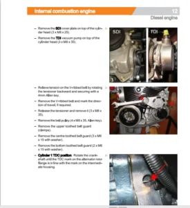
IMAGES PREVIEW OF THE MANUAL:
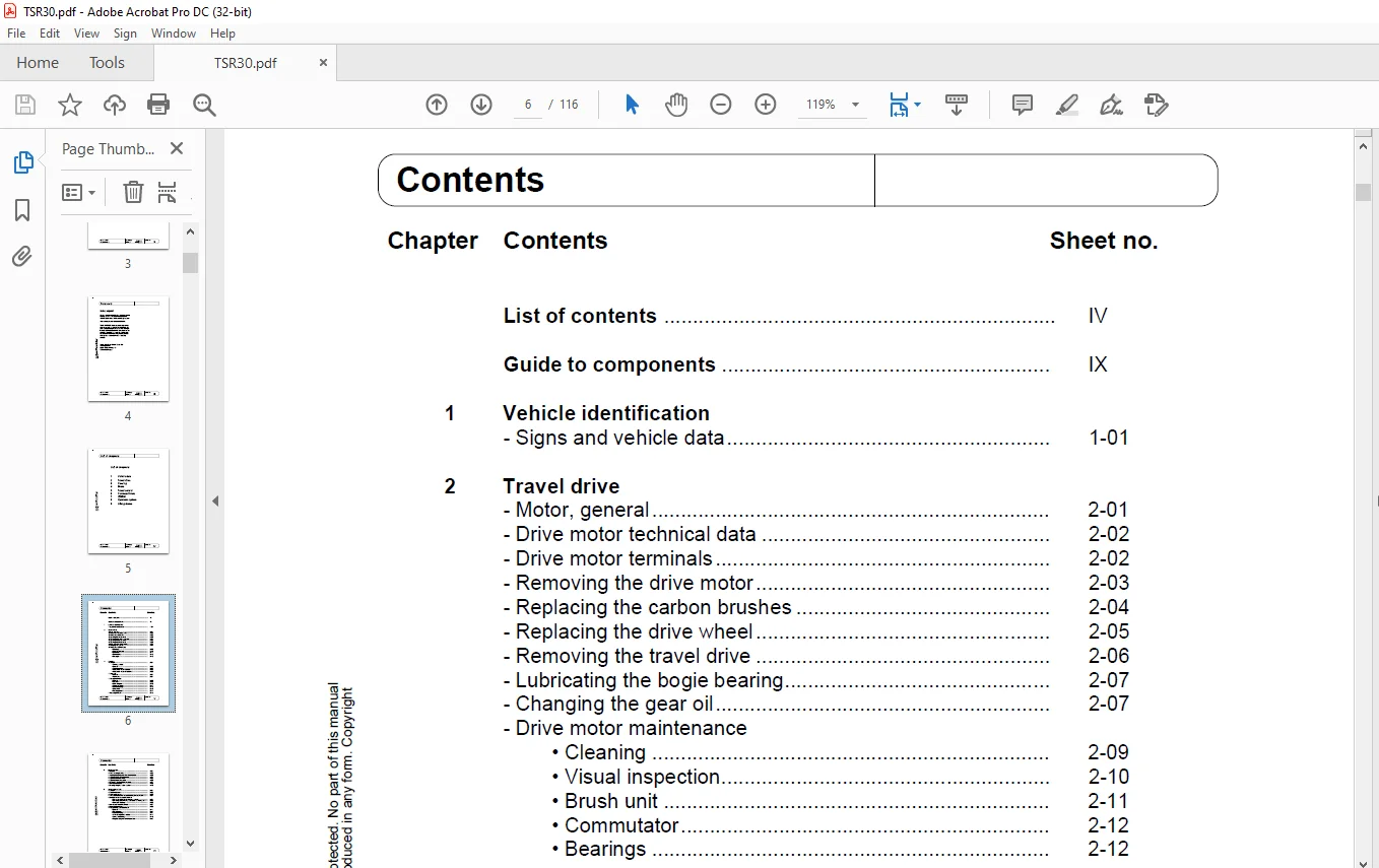
TABLE OF CONTENTS:
Still STED Forklift TSR31 Workshop Manual – PDF DOWNLOAD
List of chapters
1 Vehicle data
2 Travel drive
3 Steering
4 Brake
5 Travel control
6 Servicesoftware
7 BDI/HM
8 Hydraulic system
9 Lifting device
List of contents IV
Guide to components IX
1 Vehicle identification
– Signs and vehicle data 1-01
2 Travel drive
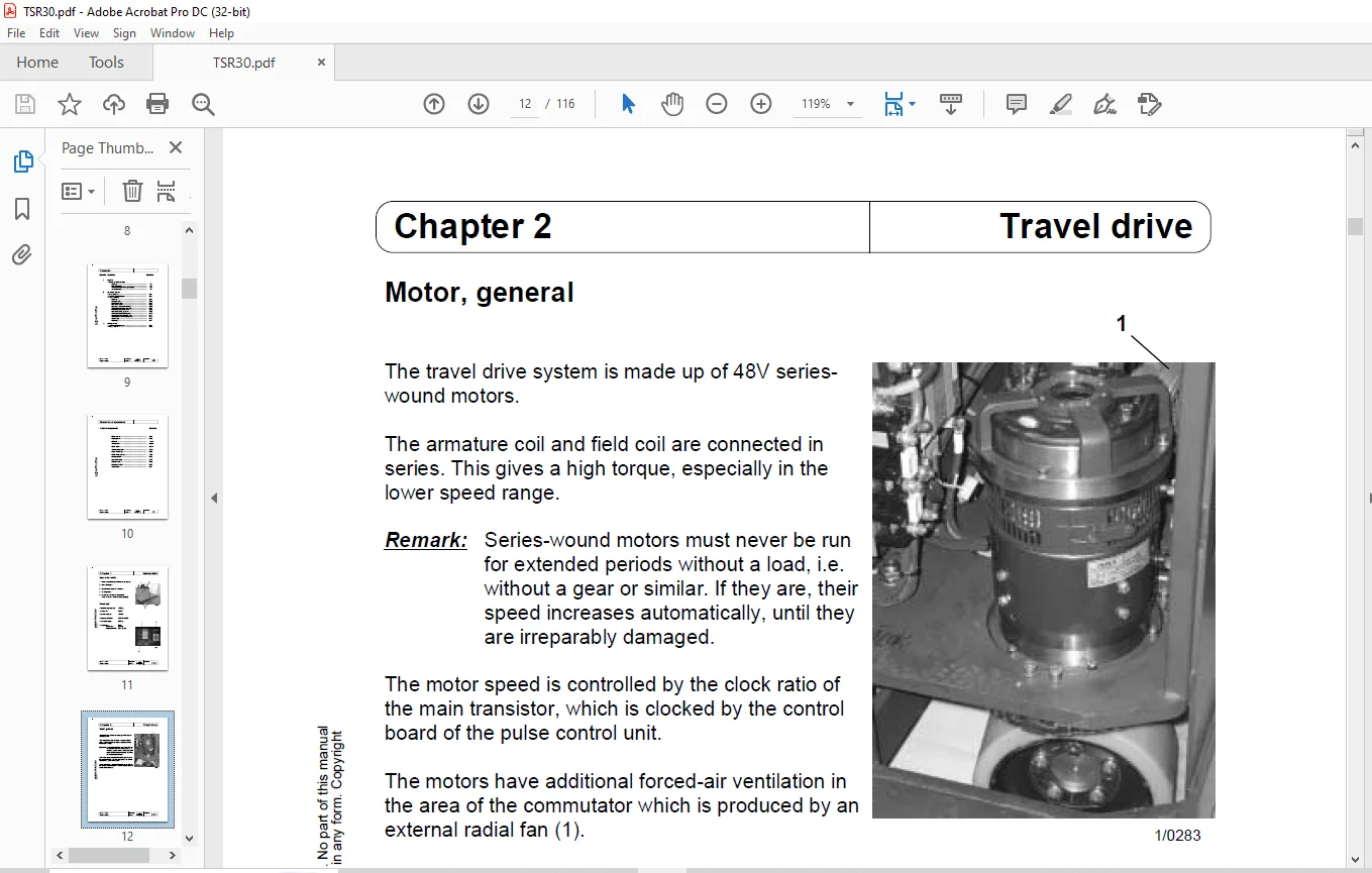
– Motor, general 2-01
– Drive motor technical data 2-02
– Drive motor terminals 2-02
– Removing the drive motor 2-03
– Replacing the carbon brushes 2-04
– Replacing the drive wheel 2-05
– Removing the travel drive 2-06
– Lubricating the bogie bearing 2-07
– Changing the gear oil 2-07
– Drive motor maintenance
• Cleaning 2-09
• Visual inspection 2-10
• Brush unit 2-11
• Commutator 2-12
• Bearings 2-12
3 Steering
– General 3-01
– Steering sensor
• General 3-02
• Slipring system 3-05
• Adjustment when installed 3-05
• Adjustment when not installed 3-06
– Servo unit
• General 3-07
• Terminals 3-07
– Steering controller
• General 3-08
• Function 3-09
• Block diagram 3-10
• Safety monitoring 3-11
• Commissioning 3-12
• Adjustment 3-13
• Pin assignment 3-14
– Track adjustment 3-15
Chapter Contents Sheet no
4 Brake system
– Function 4-01
– Guide to components 4-02
– Installing/removing the drive motor brake 4-03
– Adjusting the brake clearance 4-04
– Adjusting the handbrake 4-05
– Adjusting the brake pedal 4-06
– Measuring the brake deceleration 4-07
– Main brake cylinder 4-09
– Bleeding/filling the brake system 4-10
5 Travel control unit
– General 5-01
– Protective devices 5-02
– Operating features 5-03
– Safety instructions for commissioning and operation 5-04
– Function of the main current circuit
• Check on switching on with key switch 5-05
• Checking and switching procedure on moving off 5-05
• Generator braking 5-06
– Main current circuit terminals 5-07
– Logic card terminals 5-08
– Programming and adjustment
• General 5-11
• Configuration 5-12
• Parameterising 5-14
• Table of adjustable values 5-17
• Saving the settings 5-18
• Programming the travel transducer 5-19
• Measuring and testing functions 5-19
• Error memory 5-21
• Flashing code on diagnosis LED 5-22
• Error messages 5-23
6 Service software
– WinPulsE
• Menu guide 6-01
• Starting/stopping the connection to the control unit 6-02
• Reading data out of the control unit 6-03
• Opening/saving a data set on the computer
– Opening a file 6-04
– Saving a file with menu point “File” 6-06
– Saving a file with menu point “Parameters” 6-07
– Saving a file 6-08
• Saving data in the control unit
– Sending a data set directly to the control unit 6-09
• Changing Parameters
– Reading out parameters and changing them 6-10
– Saving parameters in the control unit 6-11
– Restoring parameters 6-11
• Changing the configuration
– Changing the configuration 6-12
– Storing a configuration 6-13
• Reading in the accelerator pedal 6-14
• Test function 6-15
• Reading out the error memory 6-16
• Changing the hour counter 6-17
• Other functions
– Closing the program (Exit) 6-18
– Software configuration 6-18
– Keyboard commands 6-19
• General 7-01
• Pin assignment 7-02
• Setting the final discharge voltage 7-03
• Technical data 7-04
8 Hydraulic system
– Block diagram 8-01
– Hydraulic circuit diagram 8-01
– Pump assembly
• General 8-02
• Lifting function 8-03
• Lowering function 8-04
• Directional valve 8-05
• Replacing the carbon brushes 8-06
• Removing the pump assembly 8-07
• Removing the pump motor 8-08
• Hydraulic pump, general 8-09
• Removing the hydraulic pump 8-10
• Dismantling the hydraulic pump 8-11
• Setting the maximum pressure 8-12
• Oil change 8-13
• Bleeding 8-14
9 Lifting device
– Adjusting the angle lever 9-01
– Lifting cylinder 9-02
• Drive wheel 2-05
• Brake pedal 4-06
• BDI/HM 7-01 ff
• Travel drive 2-06 ff
• Drive motor 2-01 ff
• Travel control unit 5-01 ff
• Field weakening 5-08
• Main brake cylinder 4-09
• Lifting cylinder 9-02
• Hydraulic pump 8-10
• Pump motor 8-06
• Directional valve 8-05
• Angle lever 9-01
Need help? Contact: [email protected]
https://vimeo.com/855663204?share=copy
PLEASE NOTE:
- This is the same manual used by the dealers to diagnose and troubleshoot your vehicle
- You will be directed to the download page as soon as the purchase is completed. The whole payment and downloading process will take anywhere between 2-5 minutes
- Need any other service / repair / parts manual, please feel free to contact [email protected] . We still have 50,000 manuals unlisted
S.M