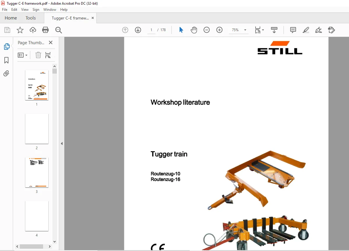
STILL STED Forklift Tugger train Routenzug-10 Routenzug-16 workshop Manual – PDF DOWNLOAD
$28.95
STILL STED Forklift Tugger train Routenzug-10 Routenzug-16 workshop Manual – PDF DOWNLOAD
Description
STILL STED Forklift Tugger train Routenzug-10 Routenzug-16 workshop Manual – PDF DOWNLOAD
FILE DETAILS:
STILL STED Forklift Tugger train Routenzug-10 Routenzug-16 workshop Manual – PDF DOWNLOAD
Language : English
Pages : 178
Downloadable : Yes
File Type : PDF
IMAGES PREVIEW OF THE MANUAL:
DESCRIPTION:
STILL STED Forklift Tugger train Routenzug-10 Routenzug-16 workshop Manual – PDF DOWNLOAD
documents.
This workshop manual contains all the information required to assist the trained service engineers with all work, repairs and maintenance on the chassis. Changes may be made at short notice and at any time, and are communicated via service information documents.
TABLE OF CONTENTS:
STILL STED Forklift Tugger train Routenzug-10 Routenzug-16 workshop Manual – PDF DOWNLOAD
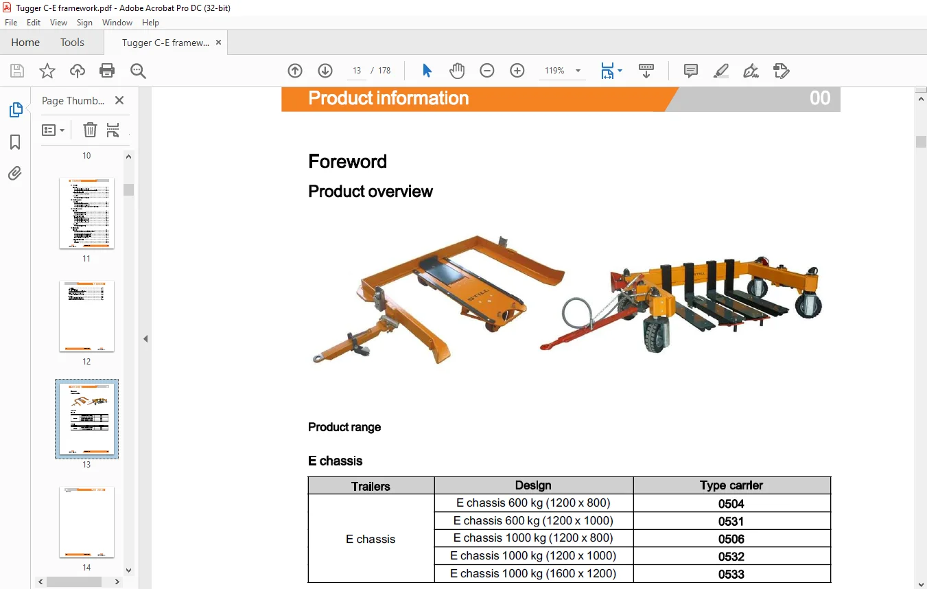
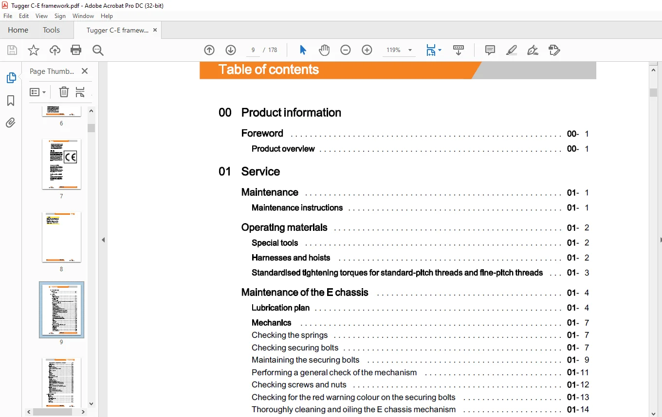
0 Product information
Foreword
Product overview
01 Service
Maintenance 01
Maintenance instructions 01
Operating materials 01
Special tools 01
Harnesses and hoists 01
Standardised tightening torques for standard-pitch threads and fine-pitch threads 01
Maintenance of the E chassis 01
Lubrication plan 01
Mechanics
Checking the springs – 7
Checking securing bolts – 7
Maintaining the securing bolts – 9
Performing a general check of the mechanism – 11
Checking screws and nuts – 12
Checking for the red warning colour on the securing bolts – 13
Thoroughly cleaning and oiling the E chassis mechanism – 14
Checking bearings and slide bushes at the securing bolts
Checking the wheels – 16
– 17
Checking the lifting function – 17
Checking hydraulic lines and connections – 18
Checking cables and hoses for wear points – 19
Checking the gasket on the hydraulic cylinders – 20
– 21
Rigid tiller – 21
Standard tiller – 24
Hinged tiller – 26
Reinforced hinged tiller – 28
Checking the springs – 35
Checking screws and nuts – 36
50988042219 [EN] VII
Table of contents
00 Product information
Foreword
Product overview
01 Service
Maintenance 01
Maintenance instructions 01
Maintenance of the self-sufficient E chassis
Maintenance instruction
Technical data
Lubrication plan
Mechanics
Operating materials 01
Special tools 01
Harnesses and hoists 01
Standardised tightening torques for standard-pitch threads and fine-pitch threads 01
Maintenance of the E chassis 01
Lubrication plan 01
Mechanics 01
Cleaning the chassis thoroughly and lubricating the moving parts -38
-41
Checking the wheels -41
-41
Checking the oil level -41
Checking the hydraulic lines -43
Checking the gasket on the hydraulic cylinders -44
Checking the toothed belt -45
Rigid tiller -48
Standard tiller -51
Hinged tiller -53
Reinforced hinged tiller -55
Testing the securing bolt -61
Maintaining the securing bolt -63
Cleaning and lubricating the mechanism -63
Checking the mechanism for general ease of movement -65
Checking for the red warning colour on the securing bolts -66
Checking the wheels for wear and ease of movement -67
Checking the bearings and rod end bearings at the wheel guides -69
Checking the lifting function -70
Checking hydraulic hoses -71
Checking the gasket on the hydraulic cylinder -72
Checking hydraulic lines and hydraulic connections -73
Checking screws and nuts -74
02 Error detection
Echassis 02
Error detection 02
Self-sufficient E chassis 02
Error detection 02
Cchassis 02
Error detection 02
Table of contents
31 Chassis
Echassis 31
Removing and installing the securing bolt 31
Removing and installing the bearing guide of the connecting link 31
Self-sufficient E chassis 31
Removing and installing the securing bolt 31
Cchassis 31
Removing and installing the securing bolt 31
42 Steering system
Cchassis 42
Removing and installing the track rods 42
Removing and installing the steering shaft 42
Removing and installing chassis bearing and tapered roller bearing 42
46 Wheels and tyres
Echassis 46
Removing and installing wheels 46
Removing and installing the axle 46
Self-sufficient E chassis 46
Tensioning the toothed belt 46
Removing and installing the toothed belt 46
Removing and installing the load wheel 46
Removing and installing the drive wheel 46
Cchassis 46
Removing and installing wheels 46
70 Hydraulics
Echassis 70
Removing and installing the pneumatic bellows cylinder 70
Removing and installing the pneumatic coupling 70
Removing and installing the hydraulic cylinders 70
Removing and installing the hydraulic coupling 70
Filling and bleeding the hydraulic system 70
X 50988042219 [EN]
Control block
Hydraulic circuit diagram
Removing and installing the hydraulic cylinders
Filling and bleeding the hydraulic system
Removing and installing the toothed belt
Cchassis
Removing and installing the lift cylinder
Filling and bleeding the hydraulic system
Customer Support: [email protected]
https://vimeo.com/856119276?share=copy
PLEASE NOTE:
- This is not a physical manual but a digital manual – meaning no physical copy will be couriered to you. The manual can be yours in the next 2 mins as once you make the payment, you will be directed to the download page IMMEDIATELY.
- This is the same manual used by the dealers inorder to diagnose your vehicle of its faults.
- Require some other service manual or have any queries: please WRITE to us at [email protected]
S.M