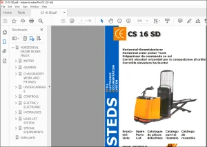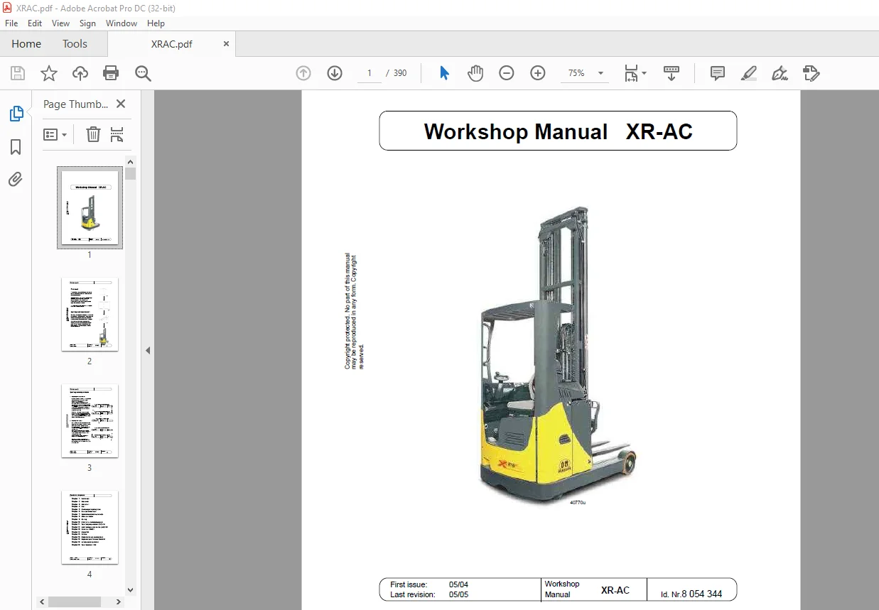
STILL STED Forklift XR-AC Workshop Manual – PDF DOWNLOAD
$29.95
STILL STED Forklift XR-AC Workshop Manual – PDF DOWNLOAD
Description
STILL STED Forklift XR-AC Workshop Manual – PDF DOWNLOAD
FILE DETAILS:
STILL STED Forklift XR-AC Workshop Manual – PDF DOWNLOAD
Language : English
Pages : 390
Downloadable : Yes
File Type : PDF
DESCRIPTION:
STILL STED Forklift XR-AC Workshop Manual – PDF DOWNLOAD
IMAGES PREVIEW OF THE MANUAL:
TABLE OF CONTENTS:
STILL STED Forklift XR-AC Workshop Manual – PDF DOWNLOAD
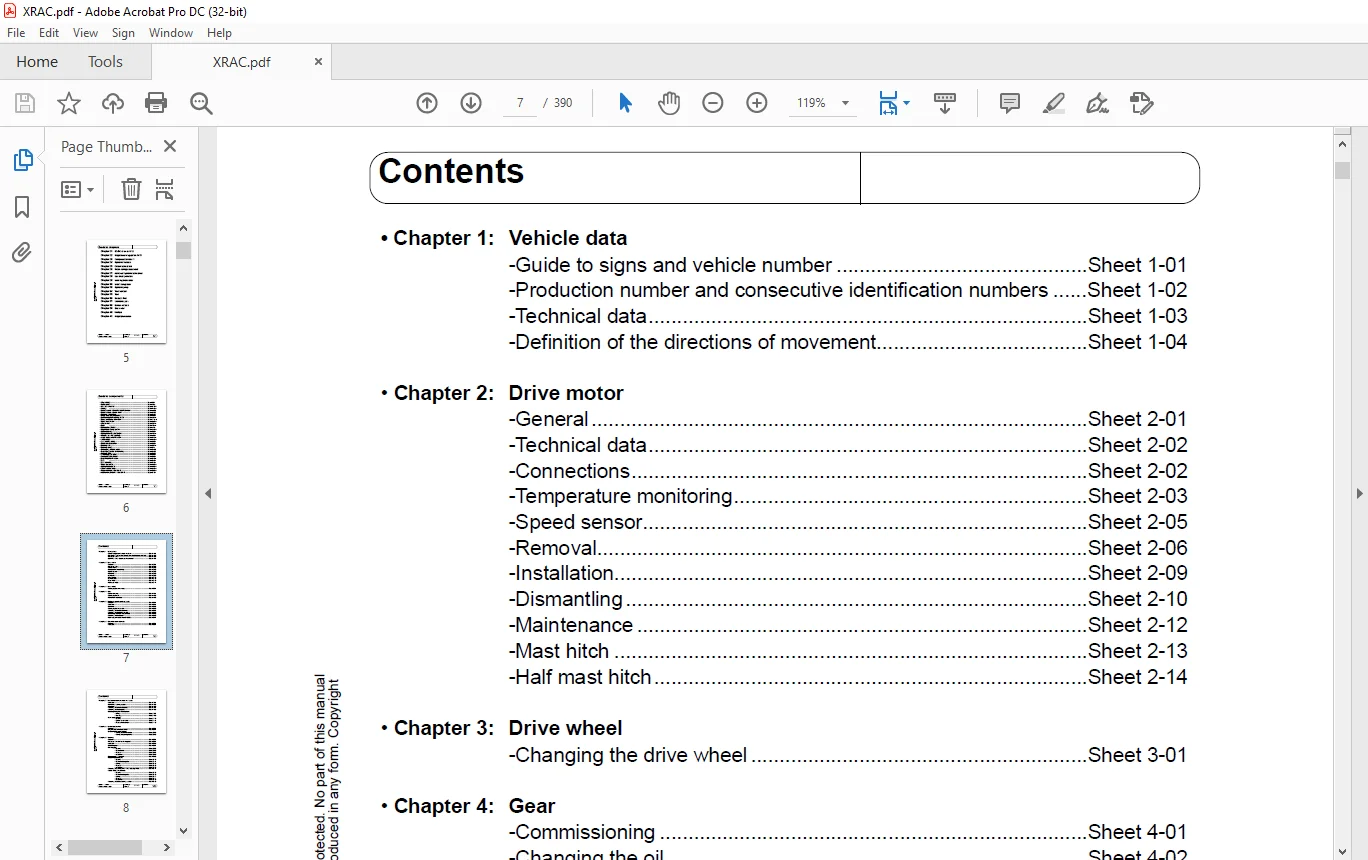
Chapter 1: Vehicle data
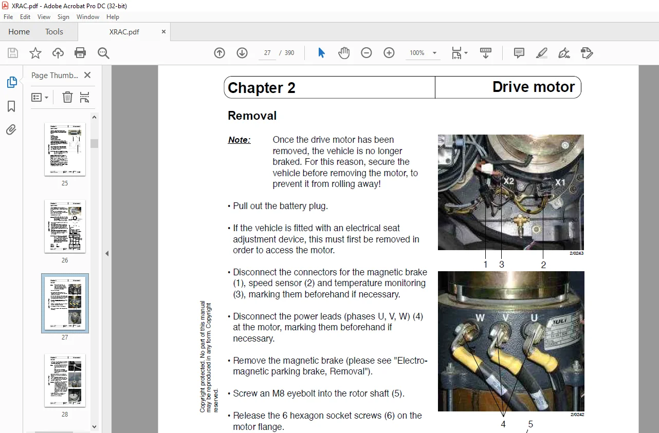
Chapter 2: Drive motor
Chapter 3: Drive wheel
Chapter 4: Gear
Chapter 5: Electro-magnetic parking brake
Chapter 6: Generator service brake
Chapter 7: Hydraulic/mechanical service brake
Chapter 8: Brake deceleration
Chapter 9: Steering
Chapter 10: Guide to the electrical components
Chapter 11: Travel and pump controller (FPS) A10
Chapter 12: Load handling controls module (LAS) 8U61
Chapter 13: Converters 1U6/2U3
Chapter 14: Display 8A5
Chapter 15: CAN bus
Chapter 16: Supply and emergency-stop circuit
Chapter 18: Single-lever potentiometers 2R9-2R13
Chapter 19: Inductive proximity switches
Chapter 20: Travel transducer 1U20
05/04
Issue: Workshop Sheet no
Guide to chapters
Replaces issue: Manual XR-AC IV Copyright protected No part of this manual
may be reproduced in any form Copyright
reserved
05/05
Chapter 21: DC/DC converter U30
Chapter 22: Height measuring system 8B21
Chapter 23: Foot pedal adjustment
Chapter 24: Hydraulic functions
Chapter 25: Chassis valve block
Chapter 26: Reach carriage valve block
Chapter 27: Additional hydraulics valve block
Chapter 28: Line break protection
Chapter 29: Lowering brake valve
Chapter 30: Load holding valve
Chapter 33: Hydraulic pump
Chapter 34: Tank indicator
Chapter 35: Tank
Chapter 36: Runback filter
Chapter 37: Lubrication plan
Chapter 38: Service software
Chapter 39: Error codes
Chapter 40: Winflash
Chapter 41: Height preselection
05/04
Guide to components
Issue: Workshop Sheet no
Replaces issue: Manual
05/05 XR-AC V Copyright protected No part of this manual
may be reproduced in any form Copyright
reserved
• Drive wheel Sheet 3-01
• Brake pedal Sheet 7-05
• DC / DC converter Sheet 21-01 ff
• Display Sheet 14-01 ff
• Speed sensor of drive/hydraulic motors Sheet 13-09
• Speed sensor of drive motor Sheet 02-05
• Pressure relief valve Sheet 25-04
• Single-lever potentiometer Sheet 18-01
• Electro-magnetic parking brake Sheet 5-01 ff
• Travel and pump controller Sheet 11-01 ff
• Travel transducer Sheet 20-01 ff
• Drive motor Sheet 2-01 ff
• Gear Sheet 4-01 ff
• Main brake cylinder Sheet 7-10
• Height measuring system Sheet 22-01 ff
• Hydraulic pump Sheet 33-01
• Hydraulic/mechanical brake Sheet 7-01 ff
• Inductive proximity switch Sheet 19-01
• Actual value potentiometer Sheet 9-15 ff
• LAS module Sheet 12-01 ff
• Load holding valve Sheet 30-01
• Line break protection Sheet 28-01
• Steering unit Sheet 9-01 ff
• Steering wheel Sheet 9-14
• Emergency release valve Sheet 25-06
• Proportional valve for lowering Sheet 25-05
• Runback filter Sheet 36-01
• Lowering brake valve Sheet 29-01
• Foot pedal adjustment Sheet 23-01
• Setpoint potentiometer Sheet 9-10 ff
• Tank Sheet 35-01
• Tank indicator Sheet 34-01
• Travel converter Sheet 13-01 ff
• Hydraulic converter Sheet 13-01 ff
• Chassis valve block Sheet 25-01 ff
• Reach carriage valve block Sheet 26-01 ff
• Additional hydraulics valve block Sheet 27-01
05/04
Contents
Issue: Workshop Sheet no
Replaces issue: Manual XR-AC VI Copyright protected No part of this manual
may be reproduced in any form Copyright
reserved
05/05
• Chapter 1: Vehicle data
-Guide to signs and vehicle number Sheet 1-01
-Production number and consecutive identification numbers Sheet 1-02
-Technical data Sheet 1-03
-Definition of the directions of movement Sheet 1-04
• Chapter 2: Drive motor
-General Sheet 2-01
-Technical data Sheet 2-02
-Connections Sheet 2-02
-Temperature monitoring Sheet 2-03
-Speed sensor Sheet 2-05
-Removal Sheet 2-06
-Installation Sheet 2-09
-Dismantling Sheet 2-10
-Maintenance Sheet 2-12
-Mast hitch Sheet 2-13
-Half mast hitch Sheet 2-14
• Chapter 3: Drive wheel
-Changing the drive wheel Sheet 3-01
• Chapter 4: Gear
-Commissioning Sheet 4-01
-Changing the oil Sheet 4-02
-Removal / installation Sheet 4-03
• Chapter 5: Electro-magnetic parking brake
-General Sheet 5-01
-Function Sheet 5-01
-Removal Sheet 5-02
-Changing the brake disk Sheet 5-03
-Adjusting the brake clearance Sheet 5-04
-Adjusting the braking moment Sheet 5-05
-Releasing the brake mechanically Sheet 5-05
-Checking the brake coil Sheet 5-06
-New magnetic brake from 04/2005 Sheet 5-07
• Chapter 6: Generator service brake
-General Sheet 6-01
-Function Sheet 6-01
05/04
Contents
Issue: Workshop Sheet no
Replaces issue: Manual XR-AC VII Copyright protected No part of this manual
may be reproduced in any form Copyright
reserved
05/05
• Chapter 7: Hydraulic/mechanical service brake
-Function Sheet 7-01
-Plan of the braking system Sheet 7-02
-Removal Sheet 7-03
-Adjusting the brake clearance Sheet 7-04
-Adjusting the brake pedal Sheet 7-05
-Bleeding/filling the brake system
• Filling Sheet 7-07
• Bleeding Sheet 7-08
-Main brake cylinder
• General Sheet 7-10
• Special base valve Sheet 7-11
• Removal/installation Sheet 7-12
• Chapter 8: Brake deceleration
-General Sheet 8-01
-Preparations for measurement Sheet 8-01
-Evaluating the measurement
• Testing the service brake Sheet 8-02
• Testing the parking brake Sheet 8-02
• Chapter 9: Steering
-General Sheet 9-01
-Technical data for the steering unit Sheet 9-01
-Function Sheet 9-02
-Block diagram Sheet 9-04
-Steering unit
• General Sheet 9-05
• Connections Sheet 9-05
• Removal Sheet 9-07
• Installation Sheet 9-08
-Removing the drive unit Sheet 9-09
-Setpoint potentiometer
• General Sheet 9-10
• Connections/signals Sheet 9-11
• Testing Sheet 9-12
• Removal Sheet 9-12
• Installation Sheet 9-13
-Adjusting the turning force of the steering wheel Sheet 9-14
-Actual value potentiometer
• General Sheet 9-15
• Connections/signals Sheet 9-16
• Testing Sheet 9-17
• Removal Sheet 9-17
• Installation Sheet 9-18
-Adjusting the entire steering system Sheet 9-19
05/04
Issue: Workshop Sheet no
Contents
Replaces issue: Manual XR-AC VIII Copyright protected No part of this manual
may be reproduced in any form Copyright
reserved
05/05
• Chapter 9: Steering
-360° Steering
• General Sheet 9-20
-Recognisable features Sheet 9-21
• Setpoint potentiometer
-General Sheet 9-22
-Connections/signals Sheet 9-23
• Actual value potentiometer
-General Sheet 9-24
-Connections/signals Sheet 9-25
• Steering unit Sheet 9-26
• Drive unit Sheet 9-27
-Software versions Sheet 9-28
• Chapter 10: Guide to the electrical components
-To 04/2005
• Basic equipment Sheet 10-01
• Options Sheet 10-02
• Block diagram Sheet 10-03
-From 05/2005
• Basic equipment Sheet 10-04
• Options Sheet 10-05
• Block diagram Sheet 10-06
• Chapter 11:Travel and pump controller (FPS) A10
-General Sheet 11-01
-Differences between FPS 2 & FPS 3 Sheet 11-01 1
-Regulating principle of the drive motor Sheet 11-02
-Regulating principle of the hydraulic motor Sheet 11-04
-Pin assignment/signals for FPS 2 Sheet 11-05
-Pin assignment/signals for FPS 3 Sheet 11-06 1
-FPS 2
• “Control OK” signal (SOK) Sheet 11-07
• Charging the capacitor unit Sheet 11-09
• Control of the main contactor Sheet 11-10
• Converter enable Sheet 11-12
• Phase monitoring Sheet 11-13
05/04
Issue: Workshop Sheet no
Contents
Replaces issue: Manual XR-AC IX Copyright protected No part of this manual
may be reproduced in any form Copyright
reserved
05/05
• Chapter 11:Travel and pump controller (FPS) A10
-FPS 3
• “Control OK” signal (SOK) Sheet 11-14
• Charging the capacitor unit Sheet 11-16
• Control of the main contactor Sheet 11-17
• Converter enable Sheet 11-19
• Phase monitoring Sheet 11-20
-Travel control signals
• Vmax Sheet 11-21
• V=2 5 km/h Sheet 11-22
-Hydraulics control signals Sheet 11-23
-Determining the battery capacity (FPS 2) Sheet 11-24
-Determining the battery capacity (FPS 3) Sheet 11-25
-Hour meter Sheet 11-26
-Anti-roll monitor Sheet 11-27
-Software versions Sheet 11-28
• Chapter 12: Load handling controls module (LAS module) 8U61
-General Sheet 12-01
-Control of the hydraulics
• General Sheet 12-02
• Block diagram Sheet 12-03
• Control signals for lifting the main lift Sheet 12-04
• Control signals for lowering the main lift Sheet 12-05
• Control signals for DS reaching Sheet 12-06
• Control signals for LS reaching Sheet 12-07
• Control signals for DS tilting Sheet 12-08
• Control signals for LS tilting Sheet 12-09
• Control signals for side shift right Sheet 12-10
• Control signals for side shift left Sheet 12-11
• Simultaneous movements Sheet 12-12
• Zero point monitoring Sheet 12-13
• Reach dampening Sheet 12-14
• Hydraulic options Sheet 12-15
• Guide to input/output signals for hydr functions Sheet 12-17
-Electro-magnetic brake control
• General Sheet 12-18
• Parking and emergency braking function Sheet 12-18
• Monitoring Sheet 12-19
-General vehicle options Sheet 12-20
05/04
Contents
Issue: Workshop Sheet no
Replaces issue: Manual XR-AC X Copyright protected No part of this manual
may be reproduced in any form Copyright
reserved
05/05
• Chapter 12: Load handling controls module (LAS) 8U61
-Safety monitoring
• General Sheet 12-21
• Switching-on sequence Sheet 12-23
• Block diagram Sheet 12-24
-Pin assignment X10 Sheet 12-25
-Pin assignment X11 Sheet 12-27
-Software versions Sheet 12-29
• Chapter 13: Converters 1U6/2U3
-General Sheet 13-01
-General (Converter to 04/2005) Sheet 13-02
-Technical data (Converter to 04/2005) Sheet 13-02
-General (Converter from 05/2005) Sheet 13-02 1
-Technical data (Converter from 05/2005) Sheet 13-02 1
-Diagram of functional principle Sheet 13-03
-The principle of speed/torque regulation Sheet 13-04
-Status LED (to 04/2005) Sheet 13-05
-Supply and enabling (from 05/2005) Sheet 13-05 1
-To 04/2005:
• Connections
– Control signals Sheet 13-06
– Power signals Sheet 13-07
• Charging the capacitor unit Sheet 13-08
• Speed sensor Sheet 13-09
• Temperature monitoring Sheet 13-10
• Converter coding Sheet 13-11
-From 05/2005:
• Connections
– Control signals Sheet 13-12
– Power signals Sheet 13-13
• Charging the capacitor unit Sheet 13-14
• Speed sensor Sheet 13-15
• Temperature monitoring Sheet 13-16
• Converter coding Sheet 13-17
05/04
Contents
Issue: Workshop Sheet no
Replaces issue: Manual XR-AC XI Copyright protected No part of this manual
may be reproduced in any form Copyright
reserved
05/05
• Chapter 14: Display 8A5
-General Sheet 14-01
-Displays Sheet 14-02
-Onboard diagnosis Sheet 14-03
• Travel program selection Sheet 14-04
• Battery type setting Sheet 14-05
• Display of the digital inputs Sheet 14-06
• Display of the analogue inputs Sheet 14-08
• Display of the vehicle type Sheet 14-12
• Software version query Sheet 14-13
-Error codes Sheet 14-14
-Software versions Sheet 14-15
• Chapter 15: CAN bus
-General Sheet 15-01
-CAN 1 bus structure (vehicle bus) Sheet 15-02
-CAN 2 bus structure (converter bus) Sheet 15-03
-Signal levels Sheet 15-04
-Data telegrams
• CAN 1 (vehicle bus) Sheet 15-05
• CAN 2 (converter bus) Sheet 15-07
-Error codes / bus test Sheet 15-08
• Chapter 16: Supply and emergency-stop circuit
-Block diagram (to 04/2005) Sheet 16-01
-Block diagram (from 05/2005) Sheet 16-02
• Chapter 18: Single-lever potentiometer 2R9-2R13
-General Sheet 18-01
-Potentiometer structure Sheet 18-02
-Resistance measurement Sheet 18-02
• Chapter 19: Inductive proximity switches
-General Sheet 19-01
• Chapter 20: Travel transducer 1U20
-General Sheet 20-01
-Measured values Sheet 20-01
-Adjustment Sheet 20-02
05/04
Contents
Issue: Workshop Sheet no
Replaces issue: Manual XR-AC XII Copyright protected No part of this manual
may be reproduced in any form Copyright
reserved
05/05
• Chapter 21: DC/DC converter U30
-General Sheet 21-01
-Technical data Sheet 21-01
-Connections Sheet 21-01
• Chapter 22: Height measuring system 8B21
-General Sheet 22-01
-Function Sheet 22-01
-Removing/installing the measuring system Sheet 22-03
-Removing the sensor bearing Sheet 22-04
-Installing the sensor bearing Sheet 22-05
• Chapter 23: Foot pedal adjustment
-General Sheet 23-01
• Chapter 24: Hydraulic functions
-Lifting the main lift Sheet 24-01
-Lowering the main lift Sheet 24-02
-Reaching Sheet 24-03
-Tilting/transverse reach/additional hydraulics Sheet 24-04
-Block diagram Sheet 24-05
• Chapter 25: Chassis valve block
-Guide to the valve block Sheet 25-01
-Functional elements Sheet 25-02
-Adjusting work
• Pressure relief valve Sheet 25-04
• Max lowering speed Sheet 25-05
-Emergency release valve Sheet 25-06
-Electrical data Sheet25-07
• Chapter 26: Reach carriage valve block
-Guide to the valve block Sheet 26-01
-Functional elements Sheet 26-02
-Adjusting work Sheet 26-04
-Electrical data Sheet 26-04
• Chapter 27: Additional hydraulics valve block
-Guide to the valve block Sheet 27-01
05/04
Contents
Issue: Workshop Sheet no
Replaces issue: Manual XR-AC XIII Copyright protected No part of this manual
may be reproduced in any form Copyright
reserved
05/05
• Chapter 28: Line break protection
-General Sheet 28-01
-Types used Sheet 28-02
• Chapter 29: Lowering brake valve
-General Sheet 29-01
-Function Sheet 29-01
• Chapter 30: Load holding valve
-General Sheet 30-01
• Chapter 33: Hydraulic pump
-General Sheet 33-01
-Types used Sheet 33-01
• Chapter 34: Tank indicator
-Tank indicator Sheet 34-01
• Chapter 35: Tank
-Tank Sheet 35-01
• Chapter 36: Runback filter
-General Sheet 36-01
-Replacing the filter Sheet 36-01
• Chapter 37: Lubrication plan
-Lubrication plan Sheet 37-01
-Lubricants Sheet 37-02
-Taking out of service / disposal Sheet 37-03
• Chapter 38: Service software
-General Sheet 38-01
-Making a connection Sheet 38-02
-FM-I Servicemaster
• Menu guide Sheet 38-03
• Commissioning the steering, general Sheet 38-05
-Commissioning the steering 180° Sheet 38-06
-Commissioning check 180°-system Sheet 38-09
-Correcting the straight-on position 180°-system Sheet 38-09
-Adjusting the flutter 180°-system Sheet 38-11
-A/D converter calibration 180°-system Sheet 38-17
-Correcting the steering speed 180°-system Sheet 38-19
-Setting the gear transmission ratio 180°-systemSheet 38-19 1
05/04
Issue: Workshop Sheet no
Contents
Replaces issue: Manual XR-AC XIV Copyright protected No part of this manual
may be reproduced in any form Copyright
reserved
05/05
• Chapter 38: Service software
-FM-I Servicemaster
-Reverse steering 180°-system Sheet 38-20
-Commissioning the steering 360° Sheet 38-21
-Adjustment steering wheel turns 360°-system Sheet 38-26
-A/D converter calibration 360°-system Sheet 38-27
-Adjusting the flutter 360°-system Sheet 38-28
-Setting the gear transmission ratio 360°-system Sheet 38-31
-Error messages for teaching-in 180° and 360° Sheet 38-32
• Commissioning the hydraulics Sheet 38-40
-Commissioning with standard parameter set Sheet 38-42
-Recommended values for initial commissioning Sheet 38-50
-Commissioning with vehicle-specific file Sheet 38-53
-Commissioning with LAS module data Sheet 38-54
-Teaching-in of the 4-lever system Sheet 38-55
• Loading parameters Sheet 38-56
• Diagnosis Sheet 38-57
-Error memory Sheet 38-58
-List of errors Sheet 38-60
-Analogue values for hydraulics Sheet 38-63
-Analogue values for steering Sheet 38-64
-Input switching signals LAS / FPS Sheet 38-65
-Travel transducer Sheet 38-67
-Travel drive Sheet 38-68
-Hydraulic drive Sheet 38-69
-Version information Sheet 38-70
• LAS module software update Sheet 38-71
• Setting the parameters in the FPS Sheet 38-75
-Travel parameters Sheet 38-76
-Operating hour counter Sheet 38-78
-Battery type Sheet 38-79
-Hydraulics characteristics Sheet 38-80
• Chapter 39: Error codes
-Description of errors Sheet 39-01
05/04
Issue: Workshop Sheet no
Contents
Replaces issue: Manual XR-AC XV Copyright protected No part of this manual
may be reproduced in any form
Copyright reserved
05/05
• Chapter 40:Winflash
Version V1 06
-General Sheet 40-01
-Block diagram Sheet 40-02
-Description Sheet 40-03
-Setting up a connection with the vehicle Sheet 40-07
-Downloading the FPS software Sheet 40-08
-Downloading the steering software Sheet 40-09
-Downloading the LAS module software Sheet 40-10
-Updating programs Sheet 40-12
Version V1 11
-General Sheet 40-13
-Preparation for downloading to the CAN control system Sheet 40-15
-Selecting the truck Sheet 40-16
-Selecting the control system Sheet 40-17
-Selecting the file Sheet 40-18
-Checking the connection Sheet 40-19
-Programming start Sheet 40-20
-End program Sheet 40-21
• Chapter 41:Height preselection
-Height preselection functions
• General Sheet 41-01
-Insertion, Removal, Assistant, Pallet free-lift Sheet 41-02
-Reference cycle, Reference height Sheet 41-03
• Function Sheet 41-04
-Incremental encoder, Reference switch Sheet 41-05
-Inductive proximity switch, Fork free-lift switch Sheet 41-06
• Block diagram Sheet 41-07
• Operation
-Insertion/removal Sheet 41-08
-Insertion Sheet 41-10
-Removal Sheet 41-11
-Target correction Sheet 41-12
-Teaching-in the levels Sheet 41-13
-Display functions
• General Sheet 41-15
• Displays and key assignment Sheet 41-16
• Operation
-On-board diagnosis Sheet 41-18
-Adjusting the proportional valve for lowering Sheet 41-25
Questions? Email us: [email protected]
https://vimeo.com/854906036?share=copy
PLEASE NOTE:
- This is the same manual used by the dealers to diagnose and troubleshoot your vehicle
- You will be directed to the download page as soon as the purchase is completed. The whole payment and downloading process will take anywhere between 2-5 minutes
- Need any other service / repair / parts manual, please feel free to contact [email protected] . We still have 50,000 manuals unlisted
S.M