Trusted Business
Verified & Licensed
Virus Free Files
100% Safe Downloads
Secure Payment
SSL Protected
Instant Delivery
Available Immediately
Still STED Order Picker CX20 CX-M 10 CX-S 16 CX-Z30 workshop Manual – PDF DOWNLOAD
$28.95
Still STED Order Picker CX20 CX-M 10 CX-S 16 CX-Z30 workshop Manual – PDF DOWNLOAD
Instant PDF Download
Available immediately
Save to Your Device
Download & keep forever
Antivirus Scanned
100% virus-free
Trusted Worldwide
175,000+ customers
Description
Still STED Order Picker CX20 CX-M 10 CX-S 16 CX-Z30 workshop Manual – PDF DOWNLOAD
FILE DETAILS:
Still STED Order Picker CX20 CX-M 10 CX-S 16 CX-Z30 workshop Manual – PDF DOWNLOAD
Language : English
Pages : 168
Downloadable : Yes
File Type : PDF
DESCRIPTION:
Still STED Order Picker CX20 CX-M 10 CX-S 16 CX-Z30 workshop Manual – PDF DOWNLOAD
General product information
Introduction
Layout
This workshop manual essentially has 2 parts,
namely:
• General information on the product, diagnosis
of breakdowns and specific tools: Group 0
• Repair instructions: Groups 1 to 9
- Each part of the current manual is composed of a set of separate sheets that are filed in a STILL binder according to their group number. The manual is organised according to the same rules used for the spare parts catalogue, which is divided into sub-groups (assemblies or construction groups).
- To make it as simple as possible to identify the assemblies presented in this manual, the number of each assembly is printed in the upper right-hand corner of each page. Where necessary, we have included tables to provide the maintenance department with relevant technical data.
- These tables must also be consulted by experienced mechanics. The manual contains a detailed description of truck design characteristics as well as component and assembly operating characteristics. To supplement the operations described in this manual, notes, instructions and explanatory diagrams have been provided.
IMAGES PREVIEW OF THE MANUAL:
TABLE OF CONTENTS:
Still STED Order Picker CX20 CX-M 10 CX-S 16 CX-Z30 workshop Manual – PDF DOWNLOAD
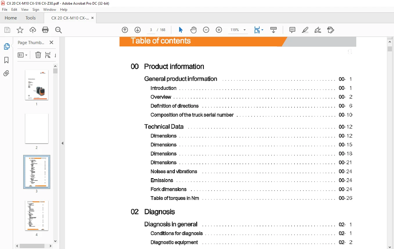
00 Product information
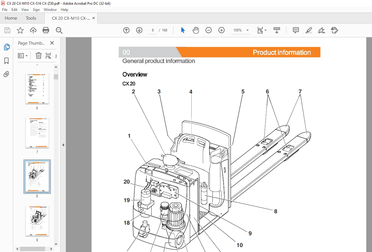
General product information
Introduction
Overview
Definition of directions
Composition of the truck serial number
Technical Data
Dimensions Dimensions Dimensions Dimensions
Noises and vibrations
Emissions
Fork dimensions
Table of torques in Nm
General product information
Introduction
Overview
Definition of directions
Composition of the truck serial number
Technical Data
Dimensions Dimensions Dimensions Dimensions
Noises and vibrations
Emissions
Fork dimensions
Table of torques in Nm
02 Diagnosis
Diagnosis in general
Conditions for diagnosis
Diagnostic equipment
CAN bus
Software
Diagnostic software
Diagnosis in general
Conditions for diagnosis
Diagnostic equipment
CAN bus
Software
Diagnostic software
10 Motor in general
Motor in general
AC asynchronous motor
Motor in general
AC asynchronous motor
11 Electric motors
Traction motor
Technical data
Traction motor- removal and installation
Traction motor
Technical data
Traction motor- removal and installation
20 Gearbox
Gearbox – general
Technical data
Gearbox – general
Technical data
Hydraulic oil reservoir
Brush renewal
Roller bearings
Brush renewal
Roller bearings
76 Valves
Directional control valve/ control valve
Lowering solenoid valve
Directional control valve/ control valve
Lowering solenoid valve
80 Load lifting system
Load lifting system – general
Technical Data
Initial lift device
Lift cylinder
Mast and fork carriage
Servicing the lift cylinder and/or the inner mast
Load lifting system – general
Technical Data
Initial lift device
Lift cylinder
Mast and fork carriage
Servicing the lift cylinder and/or the inner mast
84 Load carrier
Fork carriage
Removal of fork carriage and mast CS 1OM
Maintenance of the scissors and joining pins
Fork carriage
Removal of fork carriage and mast CS 1OM
Maintenance of the scissors and joining pins
90 Options/ accessories
Options, accessories – general
Overview
Options, accessories – general
Overview
Annex
100 A3 circuit diagrams
Wiring diagrams
Wiring diagram
22 Mechanical drive axle
Reduction gear 22-
Removal of the reduction gear 22-
31 Chassis
Frame 31-
General 31-
eovers 31- 2
Motorcompartmentcover 31- 3
Removal of covers ex 30 Z 31- 4
Tow coupling removal ex 30 Z 31- 6
34 Operator’s compartment
Seat 34-
Folding seat 34-
42 Steering system
Electric power steering 42-
Technical data 42-
Overview 42- 2
Steering motor 42- 3
Actual value potentiometer for steering angle 42- 4
Bearing of steering angle sending unit gear 42- 7
46 Wheels and tyres
Wheels 46-
Traction wheel 46-
Stabiliser 46- 2
Load wheels
Load wheels
49 Braking system
Electric service brake 49-
Technical data 49-
Operation 49- 2
Removing the electromagnetic brake 49- 4
50 Controls
Cockpit ( control console) so-
Cockpit SOCockpit
– removal and installation 50- 2
Entering the user code 50- 4
Digicode control 50- 6
Adding the master code 50- 7
Deleting the master code 50- 8
Adding the driver’s code 50-1 0
Deleting a driver’s code 50-11
60 Electrics / electronics
Electrics / electronics – general 60-
Wiring diagram 60-
Description of components 60- 2
Technical data 60- 4
Location of components 60- 5
Battery and accessories 60- 6
Battery PzS (open-lead) 60- 6
Battery change 60- 8
Sensors 60-12
Foot interlock pedal 60-12
Height sensor 60-14
64 Electronic controls
Traction controller 64-
Controller 64-
Cooling fans – removal and installation 64-
70 Hydraulic system
Hydraulic system – general 70-
Hydraulic diagram 70-
71 Working hydraulics
Pump unit 71-
Technical Data 71-
Reducing pressure inthe pressure accumulator(option) 71- 2
Pump unit 71- 2
STILL 51038070901 [EN] Ill
Table of contents
Hydraulic oil reservoir 71- 4
Brushrenewal 71- 4
Roller bearings 71- 5
76 Valves
Directional control valve/ control valve 76- 1
Lowering solenoid valve 76-
80 Load lifting system
Load lifting system – general 80- 1
Technical Data
Initial lift device
Lift cylinder 80- 2
Mast and fork carriage 80- 2
Servicing the lift cylinder and/or the inner mast 80- 5
84 Load carrier
Fork carriage 84- 1
Removal of fork carriage and mast CS 10M 84- 1
Maintenance of the scissors and joining pins 84- 2
90 Options I accessories
Options, accessories – general 90- 1
Overview 90- 1
Annex
100 A3 circuit diagrams
Wiring diagrams 1 oo- 1
Wiring diagram 10
100 A3 circuit diagrams
Wiring diagrams
Wiring diagram
22 Mechanical drive axle
Reduction gear 22-
Removal of the reduction gear 22-
31 Chassis
Frame 31-
General 31-
eovers 31- 2
Motorcompartmentcover 31- 3
Removal of covers ex 30 Z 31- 4
Tow coupling removal ex 30 Z 31- 6
34 Operator’s compartment
Seat 34-
Folding seat 34-
42 Steering system
Electric power steering 42-
Technical data 42-
Overview 42- 2
Steering motor 42- 3
Actual value potentiometer for steering angle 42- 4
Bearing of steering angle sending unit gear 42- 7
46 Wheels and tyres
Wheels 46-
Traction wheel 46-
Stabiliser 46- 2
Load wheels
Load wheels
49 Braking system
Electric service brake 49-
Technical data 49-
Operation 49- 2
Removing the electromagnetic brake 49- 4
50 Controls
Cockpit ( control console) so-
Cockpit SOCockpit
– removal and installation 50- 2
Entering the user code 50- 4
Digicode control 50- 6
Adding the master code 50- 7
Deleting the master code 50- 8
Adding the driver’s code 50-1 0
Deleting a driver’s code 50-11
60 Electrics / electronics
Electrics / electronics – general 60-
Wiring diagram 60-
Description of components 60- 2
Technical data 60- 4
Location of components 60- 5
Battery and accessories 60- 6
Battery PzS (open-lead) 60- 6
Battery change 60- 8
Sensors 60-12
Foot interlock pedal 60-12
Height sensor 60-14
64 Electronic controls
Traction controller 64-
Controller 64-
Cooling fans – removal and installation 64-
70 Hydraulic system
Hydraulic system – general 70-
Hydraulic diagram 70-
71 Working hydraulics
Pump unit 71-
Technical Data 71-
Reducing pressure inthe pressure accumulator(option) 71- 2
Pump unit 71- 2
STILL 51038070901 [EN] Ill
Table of contents
Hydraulic oil reservoir 71- 4
Brushrenewal 71- 4
Roller bearings 71- 5
76 Valves
Directional control valve/ control valve 76- 1
Lowering solenoid valve 76-
80 Load lifting system
Load lifting system – general 80- 1
Technical Data
Initial lift device
Lift cylinder 80- 2
Mast and fork carriage 80- 2
Servicing the lift cylinder and/or the inner mast 80- 5
84 Load carrier
Fork carriage 84- 1
Removal of fork carriage and mast CS 10M 84- 1
Maintenance of the scissors and joining pins 84- 2
90 Options I accessories
Options, accessories – general 90- 1
Overview 90- 1
Annex
100 A3 circuit diagrams
Wiring diagrams 1 oo- 1
Wiring diagram 10
Questions? Email us: [email protected]
https://vimeo.com/856664861?share=copy
PLEASE NOTE:
- This is the SAME manual used by the dealers to troubleshoot any faults in your vehicle. This can be yours in 2 minutes after the payment is made.
- Contact us at [email protected] should you have any queries before your purchase or that you need any other service / repair / parts operators manual.
S.M