Still STED Tow tractor LTX70 LTX80 LTX-T08 Workshop Manual – PDF DOWNLOAD
$25.95
Still STED Tow tractor LTX70 LTX80 LTX-T08 Workshop Manual – PDF DOWNLOAD
Description
Still STED Tow tractor LTX70 LTX80 LTX-T08 Workshop Manual – PDF DOWNLOAD
FILE DETAILS:
Still STED Tow tractor LTX70 LTX80 LTX-T08 Workshop Manual – PDF DOWNLOAD
Language : English
Pages : 140
Downloadable : Yes
File Type : PDF
DESCRIPTION:
Still STED Tow tractor LTX70 LTX80 LTX-T08 Workshop Manual – PDF DOWNLOAD
Foreword
Technical description
Introduction
The tow tractor and the carrier have been developed to meet the most arduous application requirements. They comply with all current European directives. The tow tractor and the carrier have a nominal towing capacity of 6.2 to 8 tonnes and an unladen traction speed of up to 20 km/h.
There are three different models:
• The 7-tonne model
• The 8-tonne model
• The carrier model
• Minimised risk of battery damage. The truck
can be equipped with an electrolyte level
sensor Chassis The chassis is designed for maximum strength and rigidity. A low centre of gravity ensures safe road handling, and its compact size ensures excellent manoeuvrability. The traction motor and electronic control are protected within the chassis but remain easily accessible for servicing. The battery is located between the two axles to obtain maximum stability and to allow quick and easy removal. Drive and transmission A powerful 4.5-kW traction motor (AC technology) is mounted transversely on the drive axle. Power is transmitted to the rear wheels through a reduction gearbox as well as a differential.
IMAGES PREVIEW OF THE MANUAL:
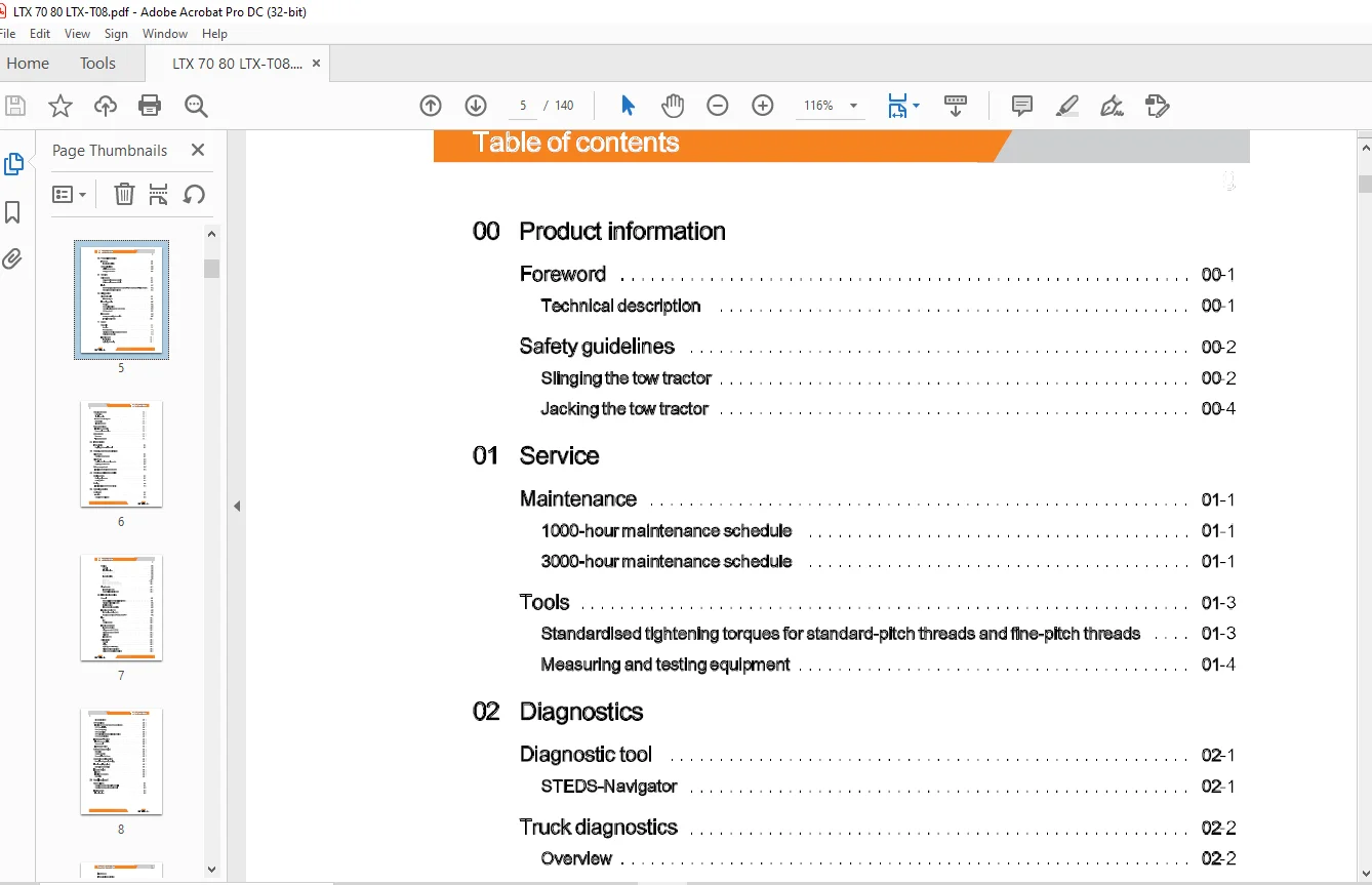
TABLE OF CONTENTS:
Still STED Tow tractor LTX70 LTX80 LTX-T08 Workshop Manual – PDF DOWNLOAD
00 Product information
Foreword 00-1
Technicaldescription 00-1
Safety guidelines 00-2
Slingingthetowtractor 00-2
Jacking the tow tractor 00-4
01 Service
Maintenance
1000-hour maintenance schedule
3000-hour maintenance schedule
01-1
01-1
01-1
Tools 01-3
Standardised tightening torques for standard-pitch threads and fine-pitch threads 01-3
Measuring and testing equipment 01-4
02 Diagnostics
Diagnostic tool
ST EDS-Navigator
Truck diagnostics
02-1
02-1
02-2
Overview 02-2
CAN box diagnostics 02-5
Connecting a laptop to the USB CAN Box 02-6
CAN bus network 02-7
Error codes 02-9
Reading and deleting the error list 02-9
TRACTION fault codes 02-11
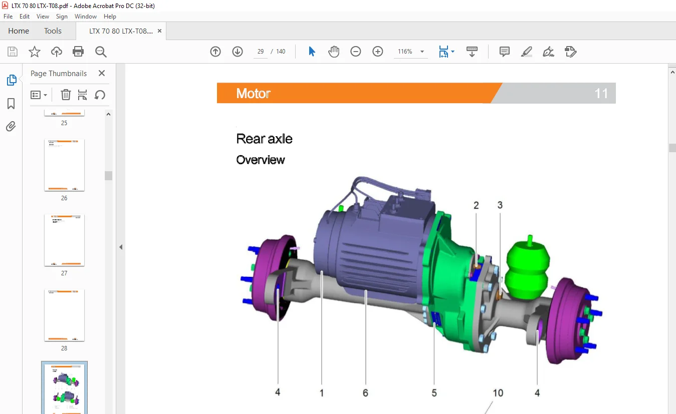
11 Motor
Rear axle 11-1
Overview 11-1
Shock absorbers 11-3
Cleaning and checking the gearbox breather 11-4
Replacing the rear axle 11-5
Traction motor 11-1 o
Technical data 11-1 0
Replacing the bearing 11-1 0
STILL 11918012101 EN -11/2016 Ill
Table of contents
Checking the motor 11-12
Preparation 11-12
Visual inspection 11-12
Traction motor winding test 11-12
Rotor testing 11-12
Cleaning the motor 11-13
Motor connections 11-14
Location of motor cables 11-14
Power module connections 11-14
Motor sensors 11-15
Revsensor 11-15
Temperature sensor 11-17
23 Transmission
Transmission 23-1
Replacing the transmission seal 23-1
30 Chassis, bodywork and fittings
Driver’s seat 30-1
Changing the seat contact 30-1
Driver’s cab 30-2
Replacing the windscreen wiper motor 30-2
Replacing the windscreen 30-4
Battery compartment 30-5
Installing and adjusting the battery door 30-5
42 Steering, braking and wheels
Steering system 42-1
Steering angle sensor 42-1
Steering column 42-2
Braking 42-3
Functional diagram of the brake circuit 42-3
50 Operating devices
IV
Accelerator 50-1
Function 50-1
Changing the accelerator 50-3
11918012101 EN -11/2016 STILL
Table of contents
Braking 50-5
General 50-5
Electrical braking 50-6
Electromagnetic brake Y1 50-6
Brake pedal 50-8
Hydraulic braking 50-9
Hydraulic brake circuit 50-9
Brake drums 50-10
Replacing the front brake drum 50-11
Replacing the front brake assembly 50-14
Blue-Q mode 50-18
Energy-saving mode 50-18
Parameterising Blue-Q mode 50-19
60 Electrics/electronics
General 60-1
Safety guidelines for electrical equipment 60-1
Cleaningtheelectricalsystem 60-2
Insulation testing 60-4
Electromagnetic compatibility 60-5
Traction controller 1A 1 60-6
LACtractioncontroller(1A1) 60-6
Functions of the “Inputs/Outputs” of the LAC 60-8
Fan 60-1 o
Fan 60-10
Changing the fan 60-12
Electric components 60-13
Emergency off switch 60-1 3
Voltage converter U 1 (7 5 W) 60-14
VoltageconverterU2(500W) 60-15
Main fuses 60-16
Line switch 1 KO 60-1 7
ABE2 display 60-18
Symbols 60-18
Display 60-20
Replacing the ABE 2 display 60-22
Maintenance interval indicator 60-23
Display of the remaining travel time 60-24
STILL 11918012101 EN -11/2016 V
Table of contents
Discharge indicator 60-25
CPP control box 60-26
Functions of CPP (Can Power Port) control boxes 60-26
CPP 1 (front lighting) 60-27
CPP 2 (rear lighting) 60-28
CPP3(caboption) 60-29
CPP 4 (electric hook and additional hydraulics) 60-30
CPP 6 (top rear lighting) 60-31
FleetManager™ (option) 60-32
FleetManager description 60-32
Access control 60-33
FleetManager options 60-34
On-board charger (option) 60-35
Description 60-35
Charger operation 60-37
Parameterising the charger 60-38
Opportunity charging (option) 60-41
Description of opportunity charging 60-41
Electric coupling (option) 60-42
Description of the coupling 60-42
Liftrunner (option) 60-43
Features 60-43
Location of components 60-46
Description 60-4 7
90 Special equipment
VI
Battery holders 90-1
ChangingthebatterywiththeForkOfftool 90-1
ChangingthebatterywiththeRollOfftool 90-4
Heating system
Electric heating
Questions? Email us: [email protected]
https://vimeo.com/853938511?share=copy
PLEASE NOTE:
- This is the SAME manual used by the dealers to troubleshoot any faults in your vehicle. This can be yours in 2 minutes after the payment is made.
- Contact us at [email protected] should you have any queries before your purchase or that you need any other service / repair / parts operators manual.
S.M