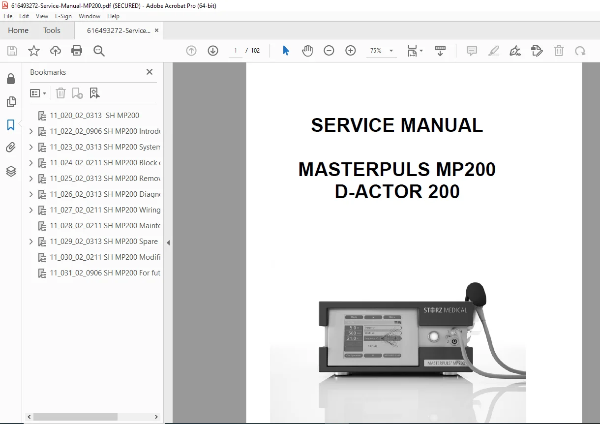
STORZ MASTERPULS MP200 D-ACTOR 200 Shockwave Therapy Service Manual PDF
Original price was: $120.00.$31.95Current price is: $31.95.
Official STORZ MEDICAL MASTERPULS MP200 and D-ACTOR 200 shockwave therapy device service manual (Article 17617). Complete technical documentation covering pneumatic radial shockwave systems for orthopedic and physiotherapy treatments. Includes system descriptions, block diagrams, removal/installation procedures, diagnostics, wiring diagrams, maintenance protocols, and spare parts catalog. Essential manual for biomedical engineers servicing extracorporeal shockwave therapy equipment.
Description
STORZ MASTERPULS MP200 D-ACTOR 200 Shockwave Therapy Service Manual 17617 PDF DOWNLOAD
DESCRIPTION
Complete STORZ MEDICAL MASTERPULS MP200 / D-ACTOR 200 Service Manual
This is the official service manual (Article Number 17617) published by STORZ MEDICAL AG for the MASTERPULS MP200 and D-ACTOR 200 radial shockwave therapy devices. This comprehensive 102-page professional service manual provides complete technical documentation for installation, troubleshooting, maintenance, and repair of STORZ pneumatic shockwave systems used in orthopedic, sports medicine, and physiotherapy applications.
📋 File Details
- Manual Name: MASTERPULS MP200 / D-ACTOR 200 Service Manual
- Article Number: 17617
- Manufacturer: STORZ MEDICAL AG, Switzerland
- Document Numbers: 11-022-02-0906 through 11-030-02-0211
- Publication Date: March/May 2013
- Pages: 102 pages
- File Quality: High-resolution PDF (A4 size)
- File Size: 3.8 MB
- Language: English
🏥 MASTERPULS MP200 / D-ACTOR 200 Overview
Device Classification:
- Type: Radial shockwave therapy system
- Application: Extracorporeal shockwave therapy (ESWT)
- Technology: Pneumatic pressure wave generation
- Control: Windows CE-based touch screen interface
Physical Specifications:
- Dimensions:
- Width: 41 cm
- Depth: 36 cm
- Height: 22 cm (17 cm without handpiece)
- Configuration: Tabletop model
- Display: 640×480 pixels color TFT LCD with touch screen
- Interface: Graphical User Interface (GUI)
System Components:
- NetDCU single board computer (Windows CE)
- Board interface with GPIO control
- Power supply unit
- Pneumatic system with pressure control
- Safety relief valve
- Pressure control valve
- Air distributor valve
- 1st and 2nd handpiece connectors
- External air compressor control
- Optional foot switch connector
- USB/LAN connectivity
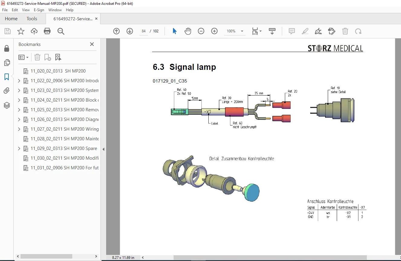
- Signal lamp indicators
Operating System:
- Platform: Windows CE
- Control: NetDCU single board computer
- Interface: Multiplexed parallel interface (8-bit bidirectional)
- Communication: Address/data lines with control signals (/ALE, /RD, /WR, /ACK)
📚 Comprehensive Manual Contents
CHAPTER 1: INTRODUCTION (Pages 1-1 to 1-10)
1.1 Copyright and Legal Information
- STORZ MEDICAL proprietary documentation
- Authorized personnel restrictions
- Service training certification requirements
1.2 Foreword
- Target audience: Authorized service personnel
- Training requirements and certification
- Contact information for technical support
1.3 Modification State of Units
- Version tracking system
- Compatibility notes
- Reference to Chapter 9 for upgrades
1.4 Format of Service Documentation
- 10-chapter logical structure
- Chapter overview diagram
- Section organization
1.5 Safety Headings Application
- CAUTION – Personal injury warnings
- ATTENTION – Equipment damage warnings
- COMMENT – Special observations and advice
1.6 Safety Instructions
- Authorized repair procedures only
- Original parts requirements
- Training prerequisites
1.7 Further Product Names
- MASTERPULS MP200 vet (veterinary version)
- D-ACTOR 200 (alternate branding)
- Model equivalencies
CHAPTER 2: SYSTEM DESCRIPTION (Pages 2-1 to 2-10)
2.1 System Overview:
- Overall dimensions with detailed measurements
- Major components identification:
- Graphical User Interface (GUI)
- NetDCU controller
- Board Interface
- Power supply
- Mains connector with fuse carrier
- Footswitch connector (optional)
- USB/LAN connector
- Compressor connector
- Safety relief valve
- Pressure control valve
- Air distributor valve
- 1st and 2nd handpiece connectors
- Signal lamp
2.2 Control Circuit:
- Windows CE operating system architecture
- NetDCU single board computer operation
- Touch panel color display interface
- Board interface gateway functionality
- Parallel interface specifications (8-bit bidirectional)
- Control signal descriptions (/ALE, /RD, /WR, /ACK)
- GPIO (General Purpose I/O) implementation
2.3 Interaction with Pneumatic Devices:
- Compressor control:
- Energy level-based pressure setting
- Valve open/close command timing
- Frequency and pulse length adjustment
- Trigger signal processing (handpiece/foot switch)
- Error condition monitoring
- Shock wave number (SW) counting
- Initial pressure setup procedures
- Handpiece control:
- Release button trigger signal
- Treatment procedure execution
- Continuous trigger mode
- Auto-trigger function (< 2 sec release)
- SW counter storage and reset
- Handpiece detection display
- Single shock mode operation (frequency = 0)
2.4 Graphical User Interface (GUI):
- 640×480 pixel color TFT LCD specifications
- Touch screen functionality
- Automatic startup/shutdown
- Single instance operation
- Function group arrangements
- Status display areas
- Treatment protocol management
- Configuration settings
- Warning/error display system
2.5 Pneumatic System:
- Pressure wave generation mechanism
- Valve control sequences
- Air distribution architecture
- Safety relief systems
- Pressure regulation
CHAPTER 3: BLOCK DIAGRAMS (Pages 3-1 to 3-10)
- System architecture diagrams
- Signal flow illustrations
- Component interconnections
- Control logic visualization
- Pneumatic system schematics
- Electrical interface diagrams
- Data communication pathways
CHAPTER 4: REMOVAL / INSTALLATION (Pages 4-1 to 4-20)
Step-by-step procedures with supporting illustrations:
- Cabinet disassembly procedures
- GUI removal and installation
- NetDCU controller replacement
- Board interface removal
- Power supply unit replacement
- Valve assemblies:
- Safety relief valve
- Pressure control valve
- Air distributor valve
- Connector replacements:
- Mains connector and fuse carrier
- Handpiece connectors (1st and 2nd)
- Compressor connector
- Footswitch connector
- USB/LAN connector
- Signal lamp replacement
- Touch screen module installation
- Internal cabling procedures
- Pneumatic component installation
- Fastener specifications
- Alignment procedures
CHAPTER 5: DIAGNOSTICS (Pages 5-1 to 5-30)
Comprehensive troubleshooting methodology:
5.1 Fault Localization Procedures
- Systematic diagnostic approach
- Test sequence protocols
- Error code interpretation
5.2 Electrical Measurements:
- Voltage testing points
- Continuity checks
- Signal verification procedures
- Power supply diagnostics
- Interface signal testing
5.3 Pneumatic System Diagnostics:
- Pressure testing procedures
- Valve functionality checks
- Air leakage detection
- Compressor performance verification
- Flow rate measurements
5.4 GUI and Control System:
- Touch screen calibration
- Display diagnostics
- Software error identification
- Communication interface testing
- NetDCU diagnostics
5.5 Treatment System Checks:
- Handpiece functionality tests
- Trigger signal verification
- Shock wave generation validation
- Frequency accuracy testing
- Energy level calibration
5.6 Error Code Reference:
- Complete error message list
- Warning conditions
- Corrective actions
- System reset procedures
5.7 Test Equipment Requirements:
- Recommended diagnostic tools
- Measurement specifications
- Calibration procedures
CHAPTER 6: WIRING DIAGRAMS (Pages 6-1 to 6-20)
Complete electrical schematics:
- Power distribution diagrams
- Control circuit schematics
- NetDCU interconnections
- Board interface wiring
- Valve control circuits
- Sensor wiring harnesses
- GUI display connections
- External device interfaces:
- Compressor connections
- Handpiece wiring
- Foot switch circuits
- USB/LAN connections
- Signal lamp circuits
- Power supply schematics
- Grounding schemes
- Cable routing diagrams
- Connector pinout tables
- Wire color coding
- Fuse specifications
CHAPTER 7: MAINTENANCE (Pages 7-1 to 7-10)
Preventive maintenance protocols:
- Daily maintenance procedures
- Weekly maintenance schedules
- Monthly maintenance tasks
- Periodic calibration requirements
- Cleaning procedures for all components
- Lubrication points and specifications
- Filter replacement schedules
- Visual inspection checklists
- Performance verification tests
- Record keeping requirements
- Consumables replacement intervals
Reference to operating manual for:
- User-level maintenance
- Routine cleaning
- Basic troubleshooting
CHAPTER 8: SPARE PARTS CATALOG (Pages 8-1 to 8-30)
Complete parts identification:
- Illustrated parts breakdowns
- Part number listings
- Component descriptions
- Ordering information
- Assembly-level views
- Individual component details
Major assemblies covered:
- GUI/Display assembly parts
- NetDCU and interface boards
- Power supply components
- Pneumatic system parts
- Valve assemblies
- Connectors and cables
- Mechanical components
- Fasteners and hardware
- Consumable items
Ordering guidelines:
- Part number format
- Minimum order quantities
- Delivery information
- Warranty coverage
CHAPTER 9: MODIFICATIONS (Pages 9-1 to 9-10)
System upgrades and changes:
- Hardware modifications documentation
- Software updates procedures
- Firmware revisions tracking
- Component upgrades specifications
- Retrofit instructions for older units
- Compatibility matrices
- Version history documentation
- Service bulletins integration
- Configuration changes procedures
Important notes:
- Modification state verification required before service
- Chapter 9 supersedes conflicting information in other chapters
- Version tracking for compliance
CHAPTER 10: TECHNICAL APPENDICES
Supporting documentation:
- Technical specifications tables
- Performance characteristics
- Safety compliance data
- Environmental specifications
- Transport and storage conditions
- Disposal regulations
- Contact information updates
⚙️ Technical Features Documented
Windows CE Control Architecture:
- Embedded operating system implementation
- Single board computer control
- Real-time response requirements
- Parallel interface communication protocol
Pneumatic Shockwave Generation:
- Pressure-controlled wave generation
- Adjustable energy levels
- Variable frequency control (0 Hz = single shock mode)
- Pulse length modulation
- Dual handpiece support
Treatment Control Features:
- Shock wave counting and tracking
- Auto-trigger functionality
- Manual trigger modes
- Error condition monitoring
- Automatic treatment termination
- Safety interlocks
User Interface:
- Color touch screen operation
- Graphical function groups
- Real-time status displays
- Treatment protocol management
- Warning/error notification
- Configuration management
- Data export capabilities (USB)
🎯 Who Should Use This Manual?
- Biomedical engineers servicing STORZ MEDICAL equipment
- Medical device technicians specialized in physiotherapy equipment
- Hospital engineering departments maintaining ESWT systems
- Authorized STORZ service personnel with certification
- Clinical engineering teams supporting orthopedic departments
- Sports medicine facility technicians maintaining therapy equipment
- Medical equipment service companies authorized by STORZ MEDICAL
- Veterinary equipment technicians (MP200 vet model)
✅ Why This Manual is Essential
✔ Official STORZ MEDICAL documentation – Authentic manufacturer service guide
✔ Complete system coverage – All components and subsystems documented
✔ Detailed removal/installation – Step-by-step procedures with illustrations
✔ Comprehensive diagnostics – Systematic troubleshooting methodology
✔ Full wiring diagrams – Complete electrical schematics
✔ Spare parts catalog – Component identification and ordering
✔ Maintenance protocols – Preventive maintenance schedules
✔ Modification tracking – System upgrade documentation
✔ Safety compliance – Required for authorized service work
✔ Training support – Essential for STORZ certification
✔ Block diagrams – Simplified system understanding
✔ Pneumatic system details – Shockwave generation technology
📥 Instant Digital Download
Receive your PDF manual immediately after purchase. Compatible with all devices – desktop, laptop, tablet, smartphone. Print sections for workshop use or keep digital for quick reference during service calls.