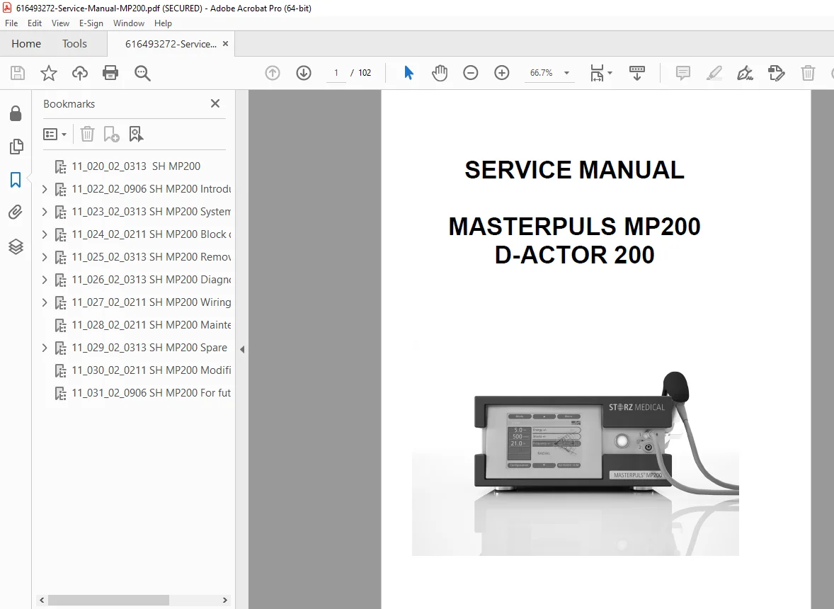
STORZ MEDICAL MASTERPULS MP200 D-ACTOR 200 Service Manual PDF
Original price was: $95.00.$31.95Current price is: $31.95.
Official factory service manual for STORZ MEDICAL MASTERPULS MP200 and D-ACTOR 200 radial shockwave therapy systems including MP200 vet veterinary model. Comprehensive technical documentation includes system descriptions, block diagrams, removal and installation procedures, diagnostic troubleshooting, wiring diagrams, pneumatic system schematics, GUI interface specifications, spare parts catalog, maintenance procedures, and modification upgrades for authorized medical equipment service technicians.
Description
STORZ MEDICAL MASTERPULS MP200 D-ACTOR 200 Service Manual Shockwave Therapy- PDF DOWNLOAD
DESCRIPTION
This comprehensive STORZ MEDICAL MASTERPULS MP200 / D-ACTOR 200 Service Manual (Article Number 17617) provides complete technical documentation for servicing and repairing STORZ MEDICAL’s advanced radial shockwave therapy systems. This professional-grade manual is essential for authorized service technicians, biomedical equipment specialists, and certified STORZ MEDICAL service personnel working on these sophisticated medical therapeutic devices.
Models Covered
This service manual provides complete technical information for the following STORZ MEDICAL shockwave therapy systems:
MASTERPULS MP200:
- Primary radial pressure wave therapy system
- Medical and physiotherapy applications
- Advanced pneumatic pressure wave generation
MASTERPULS MP200 vet:
- Veterinary version for animal therapy
- Adapted specifications for veterinary medicine
- Equine and companion animal treatment applications
D-ACTOR 200:
- Similar platform to MP200
- Alternative branding for specific markets
- Equivalent technical specifications and components
Document Information
Article Number: 17617
Document Number: 11-022-02-0906
Total Pages: 102 pages
Format: A4 size (595.22 x 842 pts)
Publication Date: March 7, 2013
Last Modified: May 28, 2013
Copyright: STORZ MEDICAL AG
Author: SMAG/SE/TD (Technical Documentation Department)
Manufacturer Information
STORZ MEDICAL AG
Training & Documentation Department
Lohstampfestrasse 8
CH-8274 Tägerwilen
Switzerland
Contact Information:
- Telephone: +41 71 677 4587
- Fax: +41 71 677 4509
Authorization Requirements
Authorized Service Personnel:
This service documentation is intended exclusively for personnel authorized by STORZ MEDICAL to perform repairs, maintenance, and technical modifications.
Authorization Criteria:
- Certified Training: Personnel who have attended STORZ MEDICAL service training and received completion certification
- Trained by Authorized Personnel: Individuals sufficiently trained by already-certified STORZ MEDICAL service personnel
- Technical Competence: Adequate knowledge of medical device servicing, pneumatic systems, and electronic controls
ATTENTION:
- Perform only repairs, exchanges, or adjustments mentioned in this service manual
- Use only original parts supplied and designated by STORZ MEDICAL AG
- Unauthorized modifications may compromise device safety and performance
Chapter 1: Introduction
1.1 Copyright:
- All rights reserved by STORZ MEDICAL
- No copying, duplication, or electronic processing without written permission
- Confidential documentation not for third-party distribution
1.2 Foreword:
- Manual produced in-house by STORZ MEDICAL Technical Documentation
- Aid for authorized service personnel
- Comprehensive repair and maintenance guidance
1.3 Modification State of Units:
- Installed units may have different modification states
- Service personnel must verify actual modification state before service
- Chapter 9 contains modification documentation superseding earlier sections
1.4 Format of Service Documentation:
10-Chapter Organization:
- Logical sequence arrangement
- Subdivided sections for easy navigation
- Comprehensive coverage from overview to detailed procedures
1.5 Safety Signal Words:
CAUTION:
- Risk of injury or death to personnel
- Critical safety instructions must be followed exactly
- Non-compliance may result in serious consequences
ATTENTION:
- Risk of damage to unit or system
- Technical instructions must be precisely followed
- Equipment damage possible if ignored
COMMENT:
- Special observations and work step advice
- Helpful tips and important notes
- Process clarifications
1.6 Safety Instructions:
- Physical contact with potential danger sources
- Proper handling of pneumatic components
- Electrical safety requirements
- Original parts usage mandatory
1.7 Further Product Names:
- MASTERPULS MP200 vet (veterinary version)
- D-ACTOR 200 (alternative branding)
- Technical equivalency documentation
Chapter 2: System Description
2.1 System Overview:
COMMENT:
- Basic unit documentation only
- External devices (compressor, foot switch) covered separately
- Interface components for external device interaction included
2.1.1 Overall Dimensions:
- Top View: 41 cm x 36 cm
- Front View Height: 22 cm (without handpiece), 17 cm (with handpiece)
- Compact tabletop configuration
- Optimized footprint for clinical environments
2.1.2 Major Components (Table Top Model):
Control Electronics:
- Graphical User Interface (GUI) – Touch screen control panel
- NetDCU – Network Data Control Unit
- Board Interface – Main control board interconnection
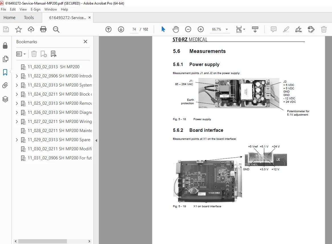
- Power Supply – Medical-grade power conversion
Electrical Connections: 5. Mains Connector with Fuse Carrier – AC power input with protection 6. Footswitch Connector – Optional hands-free operation (optional) 7. USB / LAN Connector – Data connectivity and software updates
Pneumatic System: 8. Compressor Connector – External air compressor interface 9. Safety Relief Valve – Overpressure protection 10. Pressure Control Valve – Precise pressure regulation 11. Air Distributor Valve – Pneumatic circuit distribution
Treatment Delivery: 12. 1st and 2nd Handpiece Connectors – Dual handpiece capability 13. Signal Lamp – Visual status indication
2.2 Control Circuit:
- Main control board architecture
- Signal processing and distribution
- Safety interlock systems
- Diagnostic monitoring
2.3 Interaction with Pneumatic Devices:
2.3.1 Compressor Control:
- External compressor interface protocols
- Pressure demand signaling
- Automatic start/stop control
- Pressure feedback monitoring
2.3.2 Handpiece Control:
- Pneumatic handpiece activation
- Pressure wave generation control
- Treatment parameter management
- Safety interlock verification
2.4 Graphical User Interface (GUI):
- Touch screen control system
- Treatment parameter selection
- Protocol programming
- System status display
- Diagnostic information access
- Multi-language support
2.5 Pneumatic System:
- Compressed air generation and distribution
- Pressure regulation and control
- Safety valve protection
- Handpiece delivery circuits
- Leak detection and monitoring
Chapter 3: Block Diagrams
Comprehensive system block diagrams providing:
- Complete system overview
- Component interrelationships
- Signal flow paths
- Power distribution
- Pneumatic circuit schematics
- Control logic diagrams
- Interface connections
Diagram Types:
- Functional block diagrams
- Pneumatic system schematics
- Electrical power distribution
- Control signal flow
- Safety circuit overview
- Communication interfaces
Chapter 4: Removal / Installation
Clear Step-by-Step Instructions:
- Supporting illustrations for all procedures
- Torque specifications
- Assembly sequences
- Alignment requirements
- Testing after installation
Major Assemblies Covered:
- Graphical user interface removal/installation
- NetDCU replacement procedures
- Power supply service
- Board interface access
- Pneumatic valve replacement
- Pressure control valve service
- Safety relief valve replacement
- Connector maintenance
- Handpiece interface service
Component-Level Procedures:
- Detailed disassembly instructions
- Part identification
- Wear inspection criteria
- Reassembly sequences
- Functional testing
Chapter 5: Diagnostics
Systematic Troubleshooting:
- Methodical fault isolation procedures
- Electrical measurement techniques
- Systematic test processes
- Component-level diagnostics
Diagnostic Tools and Methods:
- Voltage and current measurements
- Resistance testing
- Pneumatic pressure testing
- Signal tracing procedures
- Functional verification tests
Troubleshooting Procedures:
- Symptom-based diagnostic flowcharts
- Common fault identification
- Component testing procedures
- System performance verification
- Calibration verification
Error Code Interpretation:
- System error messages
- Fault code definitions
- Probable causes
- Resolution procedures
- Preventive measures
Chapter 6: Wiring Diagrams
Comprehensive Electrical Schematics:
- Complete wiring diagrams for all circuits
- Component location identification
- Wire color coding standards
- Connector pin-outs
- Signal routing
Circuit Documentation:
- Power supply circuits
- Control board schematics
- Interface connections
- Safety circuits
- Communication networks
- Sensor circuits
Technical Specifications:
- Voltage levels
- Current ratings
- Signal specifications
- Connector types
- Cable specifications
Chapter 7: Maintenance
Preventive Maintenance Program:
- Routine maintenance schedules
- Inspection procedures
- Cleaning protocols
- Calibration requirements
- Performance verification
Maintenance Tasks:
- Visual inspections
- Functional testing
- Pneumatic system maintenance
- Electrical system checks
- GUI calibration
- Safety system verification
Operating Manual Integration:
- Individual maintenance steps documented in operating manual
- User-level maintenance procedures
- Professional service requirements
- Maintenance interval recommendations
Chapter 8: Spare Parts Catalog
Comprehensive Parts Reference:
- Exploded view diagrams
- Part number identification
- Component descriptions
- Assembly relationships
Ordering Information:
- STORZ MEDICAL part numbers
- Quantity specifications
- Replacement interval recommendations
- Cross-reference information
Parts Categories:
- Pneumatic components
- Electrical assemblies
- Control boards
- Connectors and cables
- Handpiece parts
- Valves and regulators
- Safety components
- Wear items
Chapter 9: Modifications
System Upgrades and Changes:
- Documentation of hardware upgrades
- Software updates
- Field modifications
- Retrofit procedures
- Compatibility information
Modification Implementation:
- Upgrade instructions
- Superseded component information
- Installation procedures
- Testing and verification
- Documentation updates
COMMENT:
- This chapter may supersede corresponding sections in earlier chapters
- Always check modification state before service
- Modifications maintain or enhance device performance and safety
Chapter 10: Additional Technical Information
Supplementary documentation including:
- Technical specifications
- Performance parameters
- Environmental requirements
- Standards compliance
- Regulatory information
Key Features & Technical Highlights
✓ Radial Shockwave Therapy – Advanced pneumatic pressure wave technology
✓ Dual Handpiece Capability – Simultaneous dual treatment option
✓ Graphical User Interface – Intuitive touch screen control
✓ Pneumatic System – Precision pressure control and distribution
✓ Safety Systems – Relief valves and multiple interlocks
✓ Diagnostic Capabilities – Built-in troubleshooting and error reporting
✓ Modular Design – Component-level serviceability
✓ Medical Grade – Compliant with medical device standards
✓ Compact Design – 41 x 36 x 22 cm tabletop configuration
✓ External Device Support – Compressor, foot switch integration
Medical Applications
Therapeutic Uses:
- Musculoskeletal pain treatment
- Tendinopathy therapy
- Trigger point treatment
- Myofascial pain syndrome
- Sports medicine applications
- Rehabilitation protocols
- Veterinary physiotherapy (MP200 vet)
Service Training Requirements
STORZ MEDICAL Certification:
- Factory service training mandatory
- Hands-on practical instruction
- Theory and application knowledge
- Troubleshooting techniques
- Safety protocols
- Certification upon successful completion
Continuing Education:
- Modification update training
- Advanced diagnostic procedures
- New model familiarization
- Software update training
Technical Support
STORZ MEDICAL Service Network:
- Direct factory support available
- Technical hotline assistance
- Remote diagnostic support
- Field service coordination
- Parts ordering support
File Details
Manual Name: STORZ MEDICAL MASTERPULS MP200 / D-ACTOR 200 Service Manual
Article Number: 17617
Document Number: 11-022-02-0906 (Introduction)
System Description: 11-023-02-0313 (Chapter 2)
Total Pages: 102 pages
PDF Quality: High-quality factory manual with security features
File Size: 3.9 MB
Format: A4 size (595.22 x 842 pts)
Creator: Adobe Acrobat Pro 9.5.4
Copyright: STORZ MEDICAL AG
Confidentiality: Authorized service personnel only
Encryption: Print-enabled, copy-protected