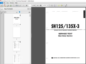
Sumitomo SH160-5 Hydraulic Excavator Service Text Manual – PDF DOWNLOAD
Original price was: $89.95.$26.95Current price is: $26.95.
Sumitomo SH160-5 Hydraulic Excavator Service Text Manual – PDF DOWNLOAD
Description
Sumitomo SH160-5 Hydraulic Excavator Service Text Manual – PDF DOWNLOAD
DESCRIPTION:
Sumitomo SH160-5 Hydraulic Excavator Service Text Manual – PDF DOWNLOAD
Language : English
Pages : 725
Downloadable : Yes
File Type : PDF
Size: 101 MB
SUMITOMO SH160-5 HYDRAULIC EXCAVATOR SERVICE TEXT MANUAL – PDF DOWNLOAD:
IMAGES PREVIEW OF THE MANUAL:


TABLE OF CONTENTS:
Sumitomo SH160-5 Hydraulic Excavator Service Text Manual – PDF DOWNLOAD
Main Body Section
Changes from Model 3
Overall Specifications 1
1 Specifications Comparison Table 1
2 Performance Improvements 2
Hydraulic-related Changes 3
1 Use of High-performance Return Filter
(nephron filter and breaker filter eliminated) 3
2 Use of Add-on Valve 5
3 Multi Purpose Circuit Switched to One-touch Operation
(breaker ⇔ crusher) 6
Hydraulic Pump 7
1 Hydraulic Pump Changes 7
2 Appearance Changes 7
3 Circuit Changes 7
4 Straight Travel Valve 8
5 Heat Circuit 9
Lower-section Related Changes 11
1 Center Joint Installation Section Notch Dimensions 11
2 Grease Bath Seal 11
3 Center Joint Rotation Stopper Installation Surface 11
4 Track Roller 12
5 Carrier Roller 13
6 Track Guard 13
Cab-related Changes 14
1 Cab Shape 14
2 Irregularly Shaped Steel Line Structure 14
3 Beefed Up Equipment 15
4 Interior Equipment 16
5 Front Window Lock Mechanism 19
Upper Swing Body Changes 20
1 High-rigidity Platform 20
1
LST-00-00-030EN
Contents
Attachment Changes 21
1 Boom 21
2 Arm 22
3 Bucket 23
4 Coupler Pin Fastening 24
5 Line Clamp 24
6 Bucket Edge Bushing 24
7 Use of Plastic Shims 24
8 Reduced Boom Foot Section Play 24
ROPS Judgment Method
ROPS Judgment Method 25
Specifications
Overall 27
1 Main Data 27
2 Performance 27
3 Main Body Dimensions 27
4 Engine 28
5 Cooling System 28
6 Upper Side Work System 29
7 Operating Device 30
8 Swing Units 31
9 Travel Lower Body 31
Hydraulic Equipment 32
1 Hydraulic Device 32
2 Control Valve, Cylinder 32
Capacities, Filters 33
1 Coolant and Oil Capacities 33
2 Hydraulic Oil Filters 33
3 Fuel Filter 33
Lifting Capacity
Precautions for lifting loads with the hydraulic excavator 35
Lifting Capacities 36
1 Standard Arm (2 62 m), 600 Grouser Shoe 36
2 Short Arm (2 23 m), 600 Grouser Shoe 37
3 Long Arm (3 05 m), 600 Grouser Shoe 38
2
Contents
LST-00-00-030EN
Overall View
Overall View (SH160-5) 39
1 Standard Arm (2 62 m) 39
2 Short Arm (2 23 m) 39
3 Long Arm (3 05 m) 40
Work Range Diagram
Work Range Diagram (SH160-5) 41
1 Standard Arm (2 62 m) 41
2 Short Arm (2 23 m) 42
3 Long Arm (3 05 m) 43
3
LST-00-00-030EN
Contents
Contents
LST-00-00-030EN
Summary Section
Main Equipment Table
Lower Component 1
1 Travel Unit 1
2 Take-up Roller 1
3 Upper-roller 1
4 Lower-roller 1
5 Recoil Spring 2
6 Shoes 2
Upper Component 3
1 Swing Unit 3
Engine-related 4
1 Engine 4
2 Muffler 5
3 Air Cleaner (double element) 5
4 Radiator 5
Hydraulic Device 6
1 Hydraulic pump 6
2 Pump P-Q Diagram 7
Control-related 8
1 Control Valve 8
2 Solenoid Valve (5-stack) 8
3 Remote Control Valve (left/right, travel operations) 9
4 Remote Control Valve Characteristic Diagram 10
5 Cushion Valve (heat circuit, with shuttle valve) 11
6 Center Joint 11
7 HBCV (option) 11
Backhoe Attachment 12
1 Cylinder 12
2 Attachments 13
Equipment Layout Diagram
3 Main Equipment Layout 15
4 Consumable Part Layout 16
Standard Machine Option List
5 List of Optional Components 17
4
LST-00-00-030EN
Contents
Contents
LST-00-00-030EN
Hydraulics Section
Hydraulic Equipment Layout
Overall View 1
Pump Chamber Hydraulic Equipment Layout 2
Swing Body Center Section Hydraulic Equipment Layout 3
Housing Left Side Hydraulic Equipment Layout 4
Layout of Hydraulic Equipment in Cab 5
Port Diagram
Pump 7
1 Hydraulic Pump (standard model) 7
Valves 8
1 Control valve 8
2 5-stack Solenoid Valve 11
3 2-stack Solenoid Valve (option) 12
4 Remote Control Valves (upper, travel) 13
5 Cushion Valve 14
6 Direction Valve/Shut-off Valve (option) 15
7 HBCV (option) 16
Manifolds 17
1 Manifold under Cab 17
2 Manifold (accumulator section) 17
3 Manifold (hydraulic oil tank section) 18
Motors 19
1 Swing Motor 19
2 Travel Motor 20
3 Center Joint 21
Pilot Hose Connection Diagram
Pilot P and T Lines 24
Pilot Control Line 26
Function List
Function Table 29
Explanation of New Functions 31
1 Swing Relief Cut Control 31
2 Negative Control Power Save Control 33
3 Option Line Flow Adjustment Control 34
4 Multi Purpose Circuit (breaker ⇔ crusher) One-touch Switching Control 35
5 Bucket-close Regenerative Circuit 36
5
LST-00-00-030EN
Contents
Explanation of Hydraulic Circuit and Operations (standard model)
Travel Circuits 38
Travel Low-speed Circuit 38
Travel High-speed Circuit 40
Straight Travel Circuit (with/without HBCV) 42
Swing Circuits 46
Swing Relief Cut-off Control Circuit 46
Swing Priority Circuit (with/without HBCV) 48
Swing Brake Circuit 52
Swing Parking Circuit (lever in neutral) 54
Swing Parking Circuit (brake release) 56
Swing Parking Circuit (machine stop) 58
Boom Circuits 60
Boom-up Circuit (single operation) (without HBCV) 60
Boom-up Circuit (single operation) (with HBCV) 62
Boom-up Circuit (compound boom-up + arm-in) (with/without HBCV) 64
Boom-down Regenerative Circuit (without HBCV) 68
Boom-down Regenerative Circuit (with HBCV) 70
Boom-down Tilting Prevention Circuit (without HBCV) 72
Boom-down Tilting Prevention Circuit (with HBCV) 74
Boom-down Load Hold Valve Circuit (with/without HBCV) 76
Arm Circuits 80
Arm-out Circuit (with/without HBCV) 80
Arm-in Forced Regenerative Circuit (with/without HBCV) 84
Arm-in Load Hold Valve Circuit (with/without HBCV) 88
Bucket Circuits 92
Bucket-open Circuit 92
Bucket-close Regenerative Circuit 94
Negative Control Circuits 96
Negative Control Circuit (power save solenoid OFF) 96
Negative Control Power Save Circuit (power save solenoid ON) 98
Negative Control Circuit (bucket-close, power save solenoid OFF) 100
Horsepower Boost Circuits 102
Arm-in Horsepower Boost Circuit (with/without HBCV) 102
Travel Horsepower Boost Circuit 106
Other Circuits 108
Cushion Circuit (arm-out Operation) 108
Cushion Circuit (arm-out Operation Stopped) 110
Cushion Circuit (arm-out → arm-in Operation) 112
Heat Circuit (lever in neutral) 114
Auto Pressure Boost Circuit (bucket-close) 116
6
Contents
LST-00-00-030EN
Explanation of Hydraulic Circuit and Operations (option)
Option Circuits 120
Breaker Circuit (single operation) 120
Shuttle Circuit (hydraulic fork) 122
Multi Purpose Circuit (breaker Q control) 124
Multi Purpose Circuit (2 Pumps flow crusher) 126
2nd Option Circuit (hydraulic rotation fork) 128
Main Equipment Structure and Operation Explanation
Pump 131
1 Hydraulic Pump 131
2 Regulator 134
3 Gear Pump 142
Motor 143
1 Travel Motor 143
2 Swing Motor 165
Valve 171
1 Control Valve 171
2 5-stack Solenoid Valve Operation Explanation 213
3 Upper Pilot Valve (remote control valve) 215
4 Travel Pilot Valve (remote control valve) 220
5 Cushion Valve 225
6 Selector Valve (3-direction) 229
7 HBCV Holding Valve 231
7
LST-00-00-030EN
Contents
Contents
LST-00-00-030EN
Electrics Section
Explanation of New Functions
Work Mode Select Switch 1
The Throttle Volume and Work Mode Select Switch are Linked!! 1
Computer Connection Method 4
Monitor Changes 5
Pilot Pressure Switch Changed to Pressure Sensor 8
Pump Electromagnetization Proportional Valve 10
1 Horsepower Control Proportional Valve 10
2 P1 Flow Control Proportional Valve 10
System Control for Energy Saving 11
1 Reduced Fuel Consumption Through Transient Load Reduction Control 11
2 Reduced Fuel Consumption Through Swing Relief Cut Control 13
3 Reduced Fuel Consumption Through Power Save Control 15
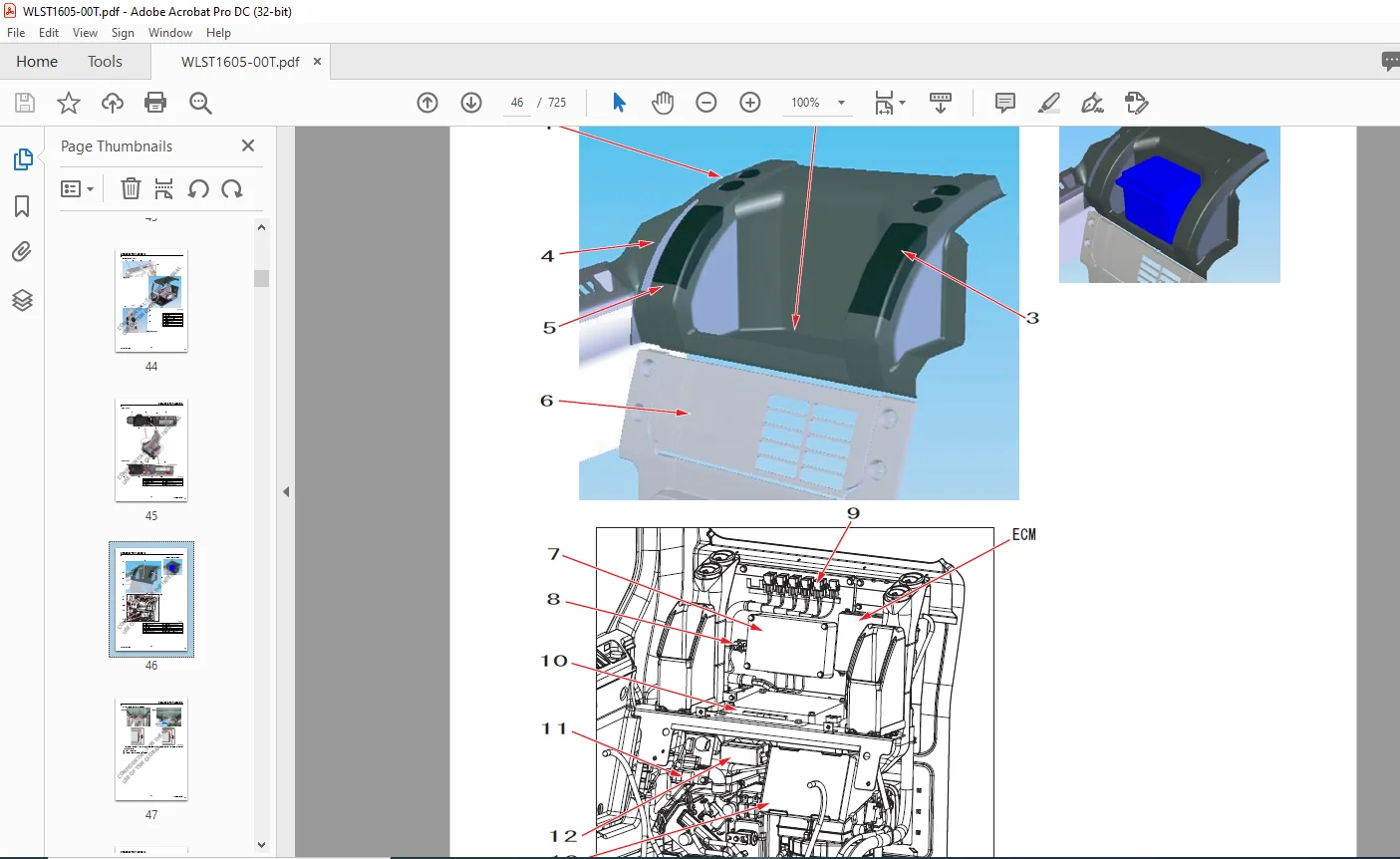
Electrical Equipment Layout Diagram
Overall View 17
1 Main Unit Right Side Layout Diagram (radiator chamber) 18
2 Engine Section Layout Diagram 19
3 Main Unit Left Side Layout Diagram (pump chamber) 20
4 Main Unit Center Section Layout Diagram 21
5 Cab Layout Diagram 22
6 Layout Around Operator Seat 24
Stand Alone Parts Diagram 25
Main Equipment Structural Diagrams
Connection Connector Pin Layout 43
1 Computer A 43
2 Monitor 44
Electrical Circuit Diagram
Overall View 46
1 Sequence Circuit Diagram 46
Block Diagram 48
1 Computer A 48
2 ECM 49
3 Monitor Display 50
4 Air Conditioner 51
5 Lever Lock 52
6 Horn 52
7 Working Light 53
8
LST-00-00-030EN
Contents
8 Option 53
9 Others 54
10 Electrical Symbol List 55
Electrical Connector Wiring Diagram
Wire Harness 58
1 Main Frame Harness 58
2 Cab Main Harness 62
3 Cab Sub Harness 66
4 In Cab 68
5 Engine Harness 70
6 Console Right Harness 72
7 Console Left Harness 72
Electrical Parts and Wiring Assembly Diagram
Main Frame 74
Cab 76
Explanation of Functions and Operations
Explanation of Electrical Functions 79
Engine Speed Control 81
1 Throttle Control 81
2 Idling Control (auto / one-touch) 85
3 Idling Start 86
4 Idle Up 87
5 Auto Warm Up 87
Engine Start / Stop Control 89
1 Engine Start / Stop Judgment 89
2 Power-cut Delay 90
3 Engine Emergency Stop 91
4 Neutral Start 93
Pump Control 94
1 Work Mode Control 94
2 Pump Horsepower Boost Control 95
3 Pump Horsepower Cut Control 96
4 Power Save Control 97
Swing 99
1 Swing Brake 99
2 Swing Lock (for maintenance) 100
3 Swing Relief Cut 102
9
Contents
LST-00-00-030EN
Travel 103
1 Travel Speed Switchover 103
2 Travel Alarm 104
Valve Control 106
1 Lever Lock 106
2 Solenoid Sticking Prevention 107
3 Pressure Boost Control 108
Monitor Control 110
1 Bar Graph
(coolant temperature gauge, oil temperature gauge, fuel gauge) 110
Accessories 117
1 Horn 117
2 Working Light 118
3 Wiper & Washer 119
4 Room Lamp 121
Others 123
1 Anti-theft 123
2 Battery Save Function 124
3 Alternator Power Generation Detection 125
Options 126
Option Line Control 126
Option Line Control 129
Feed Pump Automatic Stop 131
Return Filter Clogging Detected 134
Service Support
Screen Operations 137
1 Screen Shift 137
Screen Display List 139
1 CHK (status display) Screen List 139
2 DIAG (trouble diagnosis) Screen 149
3 HR (usage log) Screen List 151
4 CFG (setting change) Screen 156
5 CAL (troubleshooting support) Screen 160
6 Check the Monitor Switch (self-diagnosis function) 162
7 Option Flow Setting 164
8 Anti-theft Setting 166
9 Model Setting 168
10 Engine Screen Information 170
10
LST-00-00-030EN
Contents
Screen Display Details 172
1 Message Display List 172
Trouble Display 174
1 Diagnostic Trouble Code Display 174
2 Main Unit Diagnostic Trouble Code List 175
3 Diagnostic Trouble Code (monitor display) 178
4 Sensor Trouble Operation Table 184
5 EPF (Engine Protection Feature) 187
11
Contents
LST-00-00-030EN
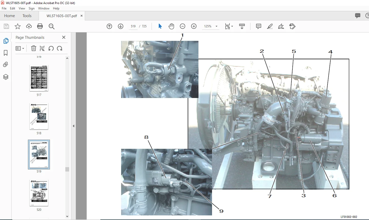
Engine Section
Engine Summary
Main Data Table (changes from model 3) 1
Overall Appearance Diagram 2
Sensor and Auxiliary Equipment Layout (left) 3
Sensor and Auxiliary Equipment Layout (rear) 4
Engine System Diagram 4
Fuel System Diagram 5
Detailed Parts Diagrams 6
1 ECM (engine control module) 6
2 Supply Pump/SCV (suction control valve) 7
3 Common Rail 7
4 Common Rail Pressure Sensor/Pressure Limiter 8
5 Injector 8
6 Engine Coolant Temperature Sensor 9
7 Engine Oil Pressure Sensor 9
8 Cam Position Sensor (CMP sensor) 10
9 Crank Position Sensor (CKP sensor) 10
10 Atmospheric Pressure Sensor 11
11 Suction Air Temperature Sensor 11
12 Boost Pressure Sensor 12
13 Boost Temperature Sensor 12
14 Charge Fuel Pump 13
15 EGR Cooler 13
16 EGR Valve 14
Engine Control Summary 14
Explanation of Engine Terms
Function Explanation Table 15
Explanation of Engine Structure
Technology for Exhaust Gases 17
Common Rail System 17
Multi-Stage Fuel Injection (multiple injection) 18
Inter Cooler 20
EGR (exhaust gas recirculation) 21
Explanation of Engine Operation
Engine Overall 23
1 Comparison of 4BG1 and 4JJ1 23
12
LST-00-00-030EN
Contents
Fuel Unit 24
1 Common Rail System Summary 24
2 Change Points for Injection Method (governor, common rail) 25
3 Explanation of Injector Operation 26
4 Explanation of Supply Pump Operation 29
5 Supply Pump Disassembly Diagram 30
6 Pressure Limiter 31
7 Cautions for Maintenance 31
Explanation of Engine Control 34
1 Fuel Injection Quantity Correction 34
2 Starting Q Correction 34
3 Preheat Control (QOS quick on start) 34
4 Atmospheric Pressure Correction (high altitude correction) 34
5 Control for Overheating 35
6 Control for Boost Temperature Rise 36
7 Control for Engine Oil Pressure Drop 36
8 Start Control (coolant temperature monitoring) 36
9 Long Cranking Control 37
10 Starting Control for Reduced Number of Cylinders 37
11 Normal Stop (key switch OFF operation) 37
12 Engine Start/Stop Judgment 38
Engine Maintenance Standards
Engine Information Screen 39
1 Purpose 39
2 How to Go to This Screen 39
3 Engine Start Restriction 39
4 Screen 39
Monitor Operation Method 40
1 View Mode 40
2 Edit Mode 40
Engine Information
(Q resistance, QR code, engine serial number) Copying Method 41
Rewriting Injector QR Codes 42
When Replacing Computer A at the Same Time 44
Engine Information Acquisition Timing 44
Redoing Engine Information Acquisition 44
Abnormality Display 44
13
Contents
LST-00-00-030EN
Engine Equipment Table
Exhaust Gas 3nd Engine Accessory Electrical Parts Compatibility
(Isuzu part number) 45
Exhaust Gas Regulations
Features of Materials Subject to Exhaust Gas Regulation 47
Exhaust Gas Regulation Values 47
Cautions for Fuel Used
Engine Fuel and Maintenance of Fuel Filters 49
1 Fuel to be applied 49
2 Maintenance of fuel filters 50
14
LST-00-00-030EN
Contents
Contents
LST-00-00-030EN
Air Conditioner Section
Changes from Model 3
Change List 1
Layout Diagram
Air Conditioner Overall Diagram 4
Frame 4
Cab 6
Equipment Layout Diagram 8
Circuit Diagram
Air Conditioner Circuit Diagram 10
Explanation of Functions
3 Explanation of Control 13
4 Air Mix Motor Actuator Control 14
5 Blow Mode Motor Actuator Control 14
6 Refresh / Recirculate Switch Motor Actuator Control 15
7 Blower Amp Control 16
8 Compressor Clutch Control 19
9 COOLMAX Control and HOTMAX Control 20
10 Trouble Detection and Control after Trouble Detected 21
11 Monitor Mode 23
12 Door Switch Control 24
13 Inside Air Filter Clogging Detection Control 25
Actuator Inspection
Air Mix Motor Actuator Inspection 29
Refresh/Recirculate Motor Actuator Inspection 31
Mode Motor Actuator Inspection 33
Self-diagnosis Function with Panel Display
Abnormality Display and Self-check Procedures 35
1 Abnormality Display Position 35
2 Explanation of Abnormality Display 35
3 Explanation of Monitor Mode 36
15
LST-00-00-030EN
Contents
Part Function and OK/NG Judgment
Control Panel and Control Unit 45
Blower Amp 45
Relay 46
Air Mix Actuator 46
Refresh / Recirculate Actuator 46
Blow Mode Actuator 47
Evaporator Sensor 47
Dual Pressure Switch 47
Solar Radiation Sensor 48
16
Contents
LST-00-00-030EN
New Machine Performance Section
New Machine Performance Judgment Table
Performance Judgment Check Sheet 1
Performance Measurement Entry Table 2
New Machine Performance Judgment Standards
Reference Values(SH160-5) 3
SP mode (With standard bucket) 3
Measurement Method and Main Unit Posture
Engine Speed 5
Pressure in Each Section 5
Cylinder Falling Amount 5
Attachment Speed 6
Swing Speed 7
Swing (180°) Brake Angle 7
Travel Speed 7
Off Travel Amount 8
Travel Sprocket Speed 8
Shoe Tension Amount 8
Turntable Bearing Movement Amount and Bucket Tip Movement Amount 9
17
LST-00-00-030EN
Contents
Contents
LST-00-00-030EN
Maintenance Section
Pressure Measurement and Adjustment Procedures
Procedures for Pressure Measurement from the Monitor Display 1
1 Pressure Measurement Method 1
2 Operating Method 1
Procedures for Measuring Hydraulic Oil Temperature from the Monitor Display 2
1 Hydraulic Oil Temperature Measurement Method 2
2 Operating Method 2
Procedures for Pressure Measurement by Installing Pressure Gauge 3
1 Preparations 3
2 Items to Prepare 3
Pressure Measuring Ports 4
Control Valve 5
1 Location of Relief Valves 5
Pressure Measurement Preparations 6
Pressure Measurement and Adjustment Procedures 9
1 Main Pressure Measurement 9
2 Pilot Pressure Measurement 13
3 Negative Control Pressure Measurement 14
Pressure Adjustment 15
1 Main Pressure Adjustment 15
2 Pilot Pressure Adjustment 19
Hydraulic Pump Flow Measurement Procedure
Preparations 21
1 Items to Prepare 21
Work Preparations 22
Flow Measurement 25
Drain Volume Measurement Procedure
Preparations 27
Travel Motor Drain Volume Measurement 27
Swing Motor Drain Volume Measurement 30
Air Bleed Procedure
Hydraulic Pump 31
Travel Motor 32
Swing Motor 33
HBCV (Option) 34
1 Boom Cylinder HBCV 34
2 Arm Cylinder HBCV 34
18
LST-00-00-030EN
Contents
Electricity Measurement Procedures
Measurement Equipment 35
Measurement Tools 36
Measurement Method 47
1 Hydraulic Pump Electromagnetic Proportional Valve 47
2 Solenoid Valve (5 stack) 48
3 Oil Temperature Sensor 50
4 Pressure Sensor 51
Procedures for Replacing Consumable Parts
Air Conditioner Belt and Fan Belt Replacement 53
1 Air Conditioner Belt Replacement 53
2 Fan Belt Replacement 55
Fuel Main Filter Replacement 58
1 Filter Replacement 58
2 Air Bleeding 61
Engine Oil Filter and Engine Oil Replacement 62
1 Engine Oil Replacement 62
2 Engine Oil Filter Replacement 64
Radiator Coolant Replacement 65
Air Cleaner Cleaning and Replacement 66
Hydraulic Oil Filter Replacement 68
1 Return Filter Replacement 68
2 Suction Filter Replacement 69
3 Air Breather Element Replacement 70
4 Pilot Oil Filter Replacement 70
5 Hydraulic Oil Replacement 71
Others 74
1 Coolant Filling 74
2 Washer Fluid Filling 74
Periodic Maintenance Procedures
Maintenance Every 250 Hours 75
1 Battery Inspection and Replacement 75
Maintenance After First 250 Hours for New Machine
/ Every 1000 Hours from Then on 76
1 Swing Reduction Gear Oil Replacement 76
2 Gear Oil Filling 77
Replace the Flange Packing at the Bottom of the Fuel Tank 78
19
Contents
LST-00-00-030EN
Bolt Size and Torque Table
Bolt and Nut Tightening 79
Retightening Torque Table 80
20
Main Unit Weight
Major Component Weight (standard specifications) 1
Individual Part Weight 2
Shoe Weight (one side) 2
Arm Weight 2
Bucket Weight 3
Interchangeability
Interchangeability 5
1 Main Part Interchangeability Table (SH160-5) 5
Attachment Installation Methods
Attachment Dimensions 7
Paint Colors
Paint Color 9
Unit Conversion Ratio
Unit Conversion Ratio 11
PLEASE NOTE:
- This is the SAME exact manual used by your dealers to fix your vehicle.
- The same can be yours in the next 2-3 mins as you will be directed to the download page immediately after paying for the manual.
- Any queries / doubts regarding your purchase, please feel free to contact [email protected]
S.V