
Sumitomo SH350LC-5 SH350HD-5 SH370HD-5 Hydraulic Excavator Service Manual WLSM3305-02W
Original price was: $98.95.$38.95Current price is: $38.95.
Sumitomo SH350LC-5 SH350HD-5 SH370HD-5 Hydraulic Excavator Service Manual WLSM3305-02W – PDF DOWNLOAD
Description
Sumitomo SH350LC-5 SH350HD-5 SH370HD-5 Hydraulic Excavator Service Manual WLSM3305-02W – PDF DOWNLOAD
DESCRIPTION:
Sumitomo SH350LC-5 SH350HD-5 SH370HD-5 Hydraulic Excavator Service Manual WLSM3305-02W – PDF DOWNLOAD
SAFETY :
[1] Before starting maintenance work, read carefully and fully understand materials (instruction manual
and maintenance manual).
[2] Before disassembling and assembling, take sufficient safety measures to prevent accidents such
as falling loads, being caught in or under the machine and burns.
When working under the machine, use safety blocks to support the machine to avoid workers
getting caught.
[3] Cranes and other hoist equipment must be operated by licensed operators.
1) Crane operators and slinging workers must be licensed.
2) Make sure to inspect rigging.
[4] Wear proper clothing and protective gear as necessary during inspection or maintenance
(safety shoes, helmets, protective goggles, gloves, earplugs, dust mask and other protective
devices).
[5] Always keep the work area clean to avoid accidents such as skidding during travel and falling
objects.
[6] Make sure to ventilate properly when inspecting or servicing a machine indoors.
[7] Be prepared for any emergencies and take necessary fire preventative measures.
Introduction :
- Appropriate operations, maintenance, inspections, troubleshooting, and repair of the machine are vital to keep it performing at its best and for the longest possible period of time, and to prevent it from breaking down. This document includes a General Outline, Specifications (Performance), Troubleshooting and Disassembly/ maintenance instructions, which are necessary for inspection, troubleshooting and repair of the machine.
- For details of the engine, refer to the maintenance manual published by the engine manufacturer. For daily inspections and maintenance, see the Operator’s Manual to take advantage of the machine’s full performance. Numerical values or others may be changed without notice due to design alterations or other reasons.
TABLE OF CONTENTS:
Sumitomo SH350LC-5 SH350HD-5 SH370HD-5 Hydraulic Excavator Service Manual WLSM3305-02W – PDF DOWNLOAD
About This Shop Manual
Safety 1
Introduction 3
Using Technical Information
Symbols 5
Precautions for Use
General Preparation for Disassembly 18
General Cautions for Assembly 20
General Cautions When Performing Inspections 24
Tightening Torque 25
Tightening Bolts and Nuts 25
Retightening Torque Table 25
Numerical Conversion Table 27
Engine Section
Procedures for Replacing Consumable Parts
Engine Oil Replacement 1
Engine Oil Filter Element Replacement 5
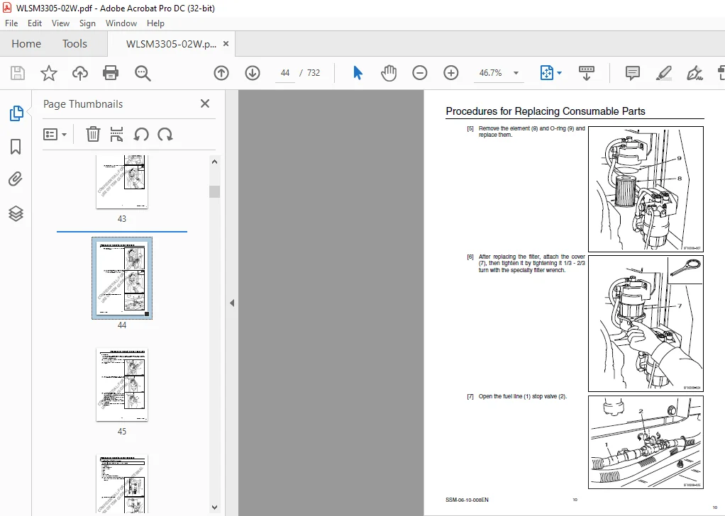
Fuel Filter Replacement 6
Charge Fuel Pump Filter Replacement 12
Air Conditioner Belt Replacement 14
Fan Belt Replacement 16
Assembly and Disassembly
Removal and Installation of Engine Hood 21
Removal and Installation of Engine Assembly 24
Removal and Installation of Starter Motor 36
Removal and Installation of Alternator 38
Removal and Installation of Supply Pump 40
Removal and Installation of Common Rail 49
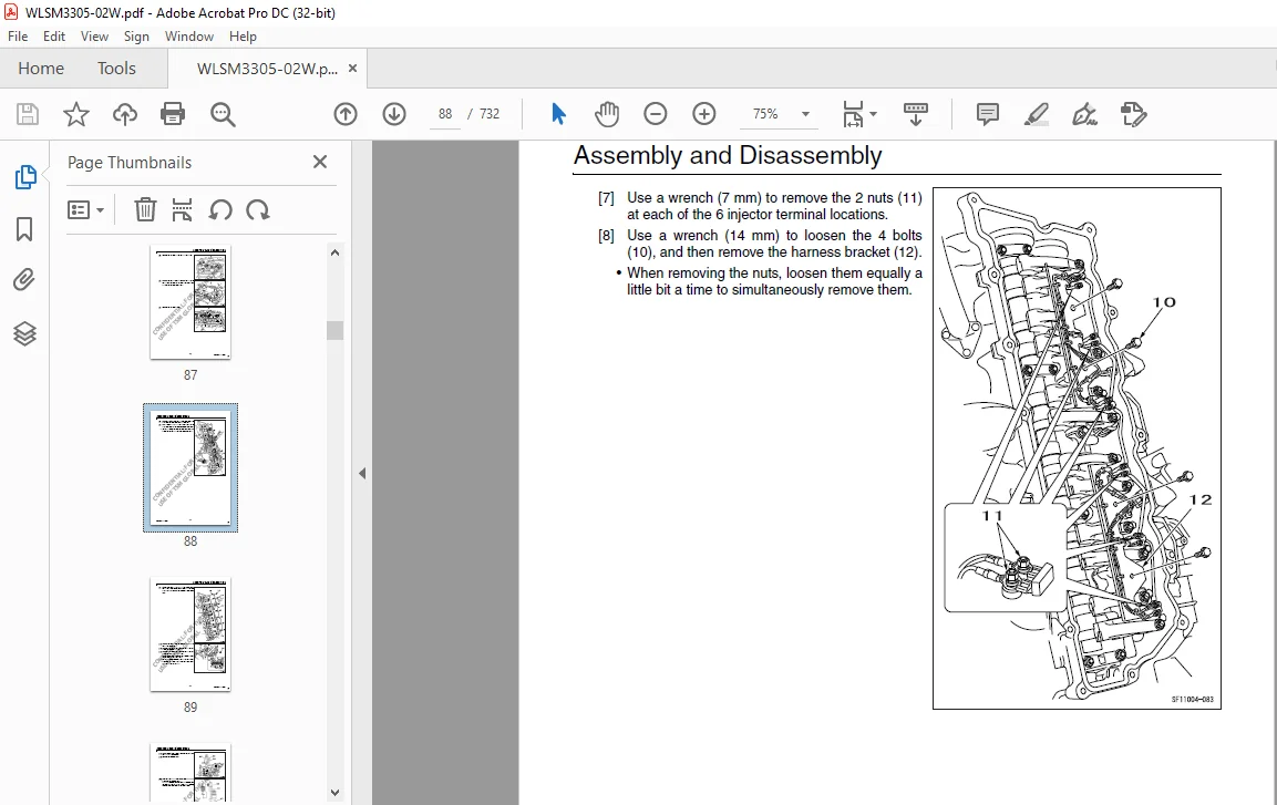
Removal and Installation of Injector 51
Removal and Installation of Muffler 63
Removal and Installation of Turbo Charger 65
Removal and Installation of EGR Cooler and EGR Valve 69
Removal and Installation of Engine Sensors 73
Removal and Installation of Fuel Cooler 75
Removal and Installation of Engine Inter Cooler 76
1
SSM-00-00-031EN 2
Contents
Air Conditioner Section
Assembly and Disassembly
Removal and Installation of Compressor 1
Removal and Installation of Condenser 3
Removal and Installation of Receiver Dryer 6
Assembly and Disassembly of Unit 8
Gas Filling Procedures
Work Precautions 13
Work Procedures 14
Filling Procedures 16
Maintenance Section
Electrical Equipment Judgment Procedures
Electricity Measurement Procedures 1
Maintenance Standards
Check Sheet 3
Inspection Gauge 15
List of Attachment Gap Adjustment Shims 17
List of Attachment Gap Adjustment Shims (for boom foot) 21
Assembly and Disassembly Section
Track Shoe
Removal and Installation of Shoe Assembly 1
Removal and Installation of Shoe Plate 6
Travel Unit
Removal and Installation of Travel Motor 7
Assembly and Disassembly of Travel Motor (made by Nabtesco) 15
Assembly and Disassembly of Travel Motor (made by KYB) 66
Take-up Roller
Removal and Installation of Take-up Roller 133
Assembly and Disassembly of Take-up Roller 135
Upper Roller
Removal and Installation of Upper Roller 145
Assembly and Disassembly of Upper Roller 147
Lower Roller
Removal and Installation of Lower Roller 159
Assembly and Disassembly of Lower Roller 162
2
Contents
3 SSM-00-00-031EN
Grease Cylinder
Removal and Installation of Grease Cylinder 173
Assembly and Disassembly of Grease Cylinder 175
Swing Unit
Removal and Installation of Swing Unit 181
Assembly and Disassembly of Swing Unit 186
Assembly and Disassembly of Swing Motor 192
Assembly and Disassembly of Swing Reduction Gear 212
Center Joint
Removal and Installation of Center Joint 235
Center Joint Assembly and Disassembly 239
Counterweight
Removal and Installation of Counterweight 249
Hydraulic Pump
Removal and Installation of Hydraulic Pump 251
Procedures for Assembly and Disassembly of Hydraulic Pump Main Unit 259
Pump Main Unit Maintenance Standards 267
Procedures for Assembly and Disassembly of Regulator 280
Remote Control Valve
Removal and Installation of Operation Remote Control Valve 295
Procedures for Assembly and Disassembly of Operation Remote Control Valve 304
Removal and Installation of Travel Remote Control Valve 317
Procedures for Assembly and Disassembly of Travel Remote Control Valve 320
Control Valve
Removal and Installation of Control Valve 341
Procedures for Assembly and Disassembly of Control Valve 347
Other Valves
Removal and Installation of 5 Stack Solenoid 373
Removal and Installation of Cushion Valve 377
Assembly and Disassembly of Cushion Valve 381
Radiator and Oil Cooler
Removal and Installation of Radiator 387
Removal and Installation of Oil Cooler 395
Tank
Removal and Installation of Hydraulic Oil Tank 401
Removal and Installation of Fuel Tank 407
3
SSM-00-00-031EN 4
Contents
Attachments
Removal and Installation of Bucket 413
Removal and Installation of Bucket Link 415
Removal and Installation of Bucket Cylinder 418
Removal and Installation of Arm Cylinder 422
Removal and Installation of Arm 427
Removal and Installation of Boom Cylinder 430
Removal and Installation of Boom 435
Removal and Installation of Arm HBCV 441
Removal and Installation of Boom HBCV 443
Procedures for Operation/Assembly and Disassembly of Hydraulic Cylinder 446
Procedures for Operation/Assembly and Disassembly of Hydraulic Cylinder 479
Procedures for Operation/Assembly and Disassembly of Hydraulic Cylinder 513
Cylinder Handling Precautions 540
Cautions for Safety 541
Lights
Removal and Installation of Boom Light 545
Removal and Installation of Tool Box Light 546
Cab Inner and Outer Parts
Removal and Installation of Cab Assembly 547
Removal and Installation of Operator’s Seat 554
Removal and Installation of Wiper 556
Removal and Installation of Wiper Controller 557
Removal and Installation of Wiper Motor 560
Removal and Installation of Monitor 563
Removal and Installation of Cab Front Glass 564
Window Lock Adjustment Procedures 566
Tightening torque 567
Hydraulic Equipment-related Parts
Removal and Installation of Accumulator 569
Removal and Installation of Suction Filter 570
Removal and Installation of Return Filter 572
Removal and Installation of Pilot Filter 574
Other
Removal and Installation of Side Door 575
Draining Oil from Hydraulic Oil Tank 576
Sumitomo SH350LC-5 SH350HD-5 SH370HD-5 Hydraulic Excavator Service Text Manual WLST3505-01T
Main Body Section
Specifications
Overall 1
1 Main Data 1
2 Performance 1
3 Main Unit Dimensions 1
4 Engine 2
5 Cooling System 2
6 Upper Side Work System 3
7 Operating Device 3
8 Swing Units 4
9 Travel Lower Body 5
Hydraulic Equipment 5
1 Hydraulic Device 5
2 Control Valve, Cylinder 6
Capacities, Filters 6
1 Coolant and Oil Capacities 6
2 Hydraulic Oil Filters 6
3 Fuel Filter 6
Lifting Capacity
Precautions for lifting loads with the hydraulic excavator 7
Lifting Capacities (SH350LC-5) 8
1 Standard Arm (3 25 m), 600 Grouser Shoe 8
2 Short Arm (2 63 m), 600 Grouser Shoe 9
3 Long Arm (4 04 m), 600 Grouser Shoe 10
4 Standard Arm (3 25 m) 800 Grouser Shoe 11
5 Short Arm (2 63 m) 800 Grouser Shoe 12
6 Long Arm (4 04 m) 800 Grouser Shoe 13
Lifting Capacities (SH350HD-5) 14
1 Standard Arm (3 25 m), 600 Grouser Shoe 14
2 Short Arm (2 63 m), 600 Grouser Shoe 15
3 Standard Arm (3 25 m), 800 Grouser Shoe 16
4 Short Arm (2 63 m), 800 Grouser Shoe 17
Lifting Capacities (SH370LHD-5) 18
1 Standard Arm (3 25 m), 600 Grouser Shoe 18
2 Short Arm (2 63 m), 600 Grouser Shoe 19
3 Standard Arm (3 25 m), 800 Grouser Shoe 20
4 Short Arm (2 63 m), 800 Grouser Shoe 21
1
SST-00-00-056EN 2
Contents
Overall View
Overall View (SH350LC-5) 23
1 Standard Arm (3 25 m) 23
2 Short Arm (2 63 m) 23
3 Long Arm (4 04 m) 24
Overall View (SH350HD-5) 25
1 Standard Arm (3 25 m) 25
2 Short Arm (2 63 m) 25
Overall View (SH370LHD-5) 26
1 Standard Arm (3 25 m) 26
2 Short Arm (2 63 m) 26
Work Range Diagram
Work Range Diagram (SH350LC-5) 27
1 Standard Arm (3 25 m) 27
2 Short Arm (2 63 m) 28
3 Long Arm (4 04 m) 29
Work Range Diagram (SH350HD-5) 30
1 Standard Arm (3 25 m) 30
2 Short Arm (2 63 m) 31
Work Range Diagram (SH370LHD-5) 32
1 Standard Arm (3 25 m) 32
2 Short Arm (2 63 m) 33
2
Contents
3 SST-00-00-056EN
Summary Section
Main Equipment Table
Lower Component 1
1 Travel Unit 1
2 Take-up Roller 1
3 Upper Roller 1
4 Lower Roller 1
5 Recoil Spring 2
6 Shoe 2
Upper Component 3
1 Swing Unit 3
Engine-related 4
1 Engine 4
2 Muffler 5
3 Air Cleaner (double element) 5
4 Pre Cleaner (option) 5
5 Radiator 6
Hydraulic Device 7
1 Hydraulic Pump 7
2 Add on Pump (option) 7
3 Pump P-Q Diagram 8
Control-related 9
1 Control Valve 9
2 Control Valve with add on section (option) 9
3 Solenoid Valve (5 stack) 10
4 Remote Control Valve (left/right, travel operations) 11
5 Remote Control Valve Characteristic Diagram 12
6 Cushion Valve (heat circuit, with shuttle valve) 14
7 Center Joint 14
Backhoe Attachment 15
1 Cylinder 15
2 Cylinder with HBCV (option) 16
3 Attachments 17
Equipment Layout Diagram
Main Equipment Layout 21
Consumable Part Layout 22
Standard Machine Option List
List of Optional Components 23
3
SST-00-00-056EN
Contents
Contents
5 SST-00-00-056EN
Hydraulics Section
Hydraulic Equipment Layout
Overall View 1
Pump Chamber Hydraulic Equipment Layout 2
Swing Body Center Section Hydraulic Equipment Layout 3
Housing Left Side Hydraulic Equipment Layout 4
Layout of Hydraulic Equipment in Cab 5
Port Diagram
Pump 7
1 Hydraulic Pump (standard model) 7
Valves 8
1 Control Valve 8
2 5 Stack Solenoid Valve 11
3 2 Stack Solenoid Valve 12
4 Remote Control Valves (upper, travel) 13
5 Cushion Valve 15
6 Direction Valve/Shut-off Valve 16
7 HBCV (option) 17
Manifolds 18
1 Manifold Under Cab 18
2 Manifold (accumulator section) 18
3 Manifold (hydraulic oil tank section) 19
Motors 20
1 Swing Motor 20
2 Travel Motor 21
3 Center Joint 22
Pilot Hose Connection Diagram
Pilot P and T Lines 24
Pilot Control Line 26
Pilot Control Line (HBCV) 28
Function List
Function Table 31
4
SST-00-00-056EN 6
Contents
Explanation of New Functions 33
1 Swing Relief Cut-off Control 33
2 Swing Speed Limit Control 34
3 Negative Control Power Save Control 35
4 Option Line Flow Adjustment Control 36
5 Multi Purpose Circuit (breaker ⇔ crusher) One-touch Switching Control 37
6 Bucket-close Regenerative Circuit 38
Explanation of Hydraulic Circuit and Operations (standard model)
Travel Circuit 40
Travel low-speed circuit 40
Travel high-speed circuit 42
Straight travel circuit 44
Swing Circuit 46
Swing speed limit control circuit 46
Swing relief cut-off control circuit 48
Swing priority circuit 50
Swing brake circuit 52
Swing parking circuit (lever in neutral) 54
Swing parking circuit (brake release) 56
Swing parking circuit (machine stop) 58
Boom Circuit 60
Boom-up circuit (independent operation) 60
Boom-up circuit (compound boom-up + arm-in) 62
Boom-down regenerative circuit 64
Boom-down tilting prevention circuit 66
Boom-down load holding valve circuit 68
Arm Circuit 70
Arm-out circuit 70
Arm-in forced regenerative circuit 72
Arm-in load holding valve circuit 74
Bucket Circuit 76
Bucket-open circuit 76
Bucket-close regenerative circuit 78
Negative Control Circuit 80
Negative control circuit (power save solenoid OFF) 80
Negative control power save circuit (power save solenoid ON) 82
Negative control circuit (bucket close, power save solenoid OFF) 84
5
Contents
7 SST-00-00-056EN
Other Circuits 86
Cushion circuit (arm-out operation) 86
Cushion circuit (arm-out operation stopped) 88
Cushion circuit (arm-out → arm-in operation) 90
Heat circuit (lever in neutral) 92
Auto pressure boost circuit (bucket close) 94
Explanation of Hydraulic Circuit and Operations (option)
Option Circuits 98
Breaker circuit (independent operation) 98
Double-acting circuit (hydraulic fork) 100
Multi-purpose circuit (breaker Q control) 102
Multi-purpose circuit (2 pumps flow crusher) 104
2nd option circuit (hydraulic rotation fork) 106
Main Equipment Structure and Operation Explanation
Pump 109
1 Hydraulic Pump 109
2 Regulator 112
3 Gear Pump 120
Motor 122
1 Travel Motor 122
2 Swing Motor 134
Valve 140
1 Control Valve 140
2 5 Stack Solenoid Valve Operation Explanation 177
3 Upper Pilot Valve (remote control valve) 178
4 Travel Pilot Valve (remote control valve) 183
5 Option Pilot Valve (remote control valve) 188
6 Cushion Valve 191
7 Direction Valve (3-direction) 195
6
SST-00-00-056EN
Contents
Contents
9 SST-00-00-056EN
Electrics Section
Explanation of New Functions
Work Mode Select Switch 1
The Throttle Volume and Work Mode Select Switch are Linked!! 1
Computer connection method 4
Monitor changes 5
Pilot pressure switch changed to pressure sensor 8
Pump Electromagnetic Proportional Valve 10
1 Horsepower Control Proportional Valve 10
2 P1 Flow Control Proportional Valve 10
System Control for Energy Saving 11
1 Reduced Fuel Consumption Through Transient Load Reduction Control 11
2 Reduced Fuel Consumption Through Swing Relief Cut Control 12
3 Reduced Fuel Consumption Through Power Save Control 14
Swing Speed Limit Control 15
Electrical Equipment Layout Diagram
Overall View 17
1 Main Unit Left Side Layout Diagram (radiator chamber) 18
2 Engine Section Layout Diagram 19
3 Main Unit Right Side Layout Diagram (pump chamber) 20
4 Main Unit Center Section Layout Diagram 21
5 Cab Layout Diagram 1 22
6 Layout Around Operator’s Seat 24
Stand Alone Parts Diagram 25
Main Equipment Structural Diagrams
Connection Connector Pin Layout 43
1 Computer A 43
2 Monitor 44
Electrical Circuit Diagram
Overall View 46
1 Sequence Circuit Diagram 46
7
SST-00-00-056EN 10
Contents
Block Diagram 48
1 Computer A 48
2 ECM 49
3 Monitor Display 50
4 Air Conditioner 51
5 Lever Lock 52
6 Horn 52
7 Working Light 53
8 Option 53
9 Other 54
10 Electrical Symbol List 55
Electrical Connector Wiring Diagram
Wire Harness 58
1 Main Frame Harness 58
Cab 62
1 Cab Main Harness 62
2 Cab Sub Harness 66
3 In Cab 68
4 Engine Harness 70
Console 71
1 Console Right Harness 71
2 Console Left Harness 72
Electrical Parts and Wiring Assembly Diagram
Main Frame 74
Cab 78
Explanation of Functions and Operations
Explanation of Electrical Functions 81
Engine Speed Control 83
1 Throttle Control 83
2 Idling Control (auto/one-touch) 87
3 Idling Start 88
4 Auto Warm-up 89
Engine Start/Stop Control 91
1 Engine Start/Stop Judgment 91
2 Power-cut Delay 92
3 Engine Emergency Stop 93
4 Neutral Start 95
8
Contents
11 SST-00-00-056EN
Pump Control 96
1 Work Mode Control 96
2 Pump Horsepower Boost Control 97
3 Pump Horsepower Cut Control 98
4 Power Save Control 99
Swing 101
1 Swing Brake 101
2 Swing Relief Cut 103
3 Swing Speed Limit 104
Travel 106
1 Travel Speed Switchover 106
2 Travel Alarm 107
Valve Control 109
1 Lever Lock 109
2 Solenoid Sticking Prevention 110
3 Pressure Boost Control 111
Monitor Control 113
1 Bar Graph
(coolant temperature gauge, oil temperature gauge, fuel gauge) 113
Accessories 119
1 Horn 119
2 Working Light 120
3 Wiper and Washer 121
4 Room Lamp 123
Other 125
1 Anti-theft 125
2 Battery Save Function 126
3 Alternator Power Generation Detection 127
Options 128
1 Option line control 128
2 Option Line Control 131
3 Feed Pump Automatic Stop 133
4 Return Filter Clogging Detected 136
Service Support
Screen Operations 139
1 Screen Shift 139
9
SST-00-00-056EN 12
Contents
Screen Display List 141
1 CHK (status display) Screen List 141
2 DIAG (trouble diagnosis) Screen 151
3 HR (usage log) Screen List 153
4 CFG (setting change) Screen 158
5 CAL (troubleshooting support) Screen 161
6 Check the Monitor Switch (self-diagnosis function) 164
7 Option Flow Setting 166
8 Anti-theft Setting 168
9 Model Setting 170
10 Engine Information Screen 172
Screen Display Details 174
1 Message Display List 174
Abnormality Display 176
1 Diagnostic Trouble Code Display 176
2 Main Unit Diagnostic Trouble Code List 177
3 Diagnostic Trouble Code (monitor display) 180
4 Sensor Trouble Operation Table 187
5 EPF (Engine Protection Feature) 190
10
Contents
13 SST-00-00-056EN
Engine Section
Engine Summary
Main Data Table 1
Overall Appearance Diagram 2
Sensor and Auxiliary Equipment Layout (left) 3
Sensor and Auxiliary Equipment Layout (rear) 4
Engine System Diagram 4
Fuel System Diagram 5
Detailed Parts Diagrams 6
1 ECM (engine control module) 6
2 Supply Pump/SCV (suction control valve) 7
3 Common Rail/Flow Damper 7
4 Common Rail Pressure Sensor/Pressure Limiter 8
5 Injector 8
6 Engine Coolant Temperature Sensor 9
7 Engine Oil Pressure Sensor 9
8 Cam Position Sensor (CMP sensor) 10
9 Crank Position Sensor (CKP sensor) 10
10 Atmospheric Pressure Sensor 11
11 Suction Air Temperature Sensor 11
12 Boost Pressure Sensor 12
13 Boost Temperature Sensor 12
14 Charge Fuel Pump 13
15 EGR Cooler 13
16 Lead Valve (check valve) 14
17 EGR Valve 14
Engine Control Summary 15
Explanation of Engine Terms
Function Explanation Table 17
Explanation of Engine Structure
Technology for Exhaust Gases 19
1 Common Rail System 19
2 Multi Stage Fuel Injection (multiple injection) 20
3 Inter Cooler 22
4 EGR (exhaust gas recirculation) 23
11
SST-00-00-056EN 14
Contents
Explanation of Engine Operation
Fuel Unit 25
1 Common Rail System Summary 25
2 Change Points for Injection Method (governor, common rail) 26
3 Explanation of Injector Operation 27
4 Explanation of Supply Pump Operation 30
5 Supply Pump Disassembly Diagram 31
6 Explanation of Flow Damper Operation 33
7 Pressure Limiter 34
8 Cautions for Maintenance 35
Explanation of Engine Control 38
1 Fuel Injection Quantity Correction 38
2 Starting Q Correction 38
3 Preheat Control (QOS: quick on start) 38
4 Atmospheric Pressure Correction (high altitude correction) 38
5 Control for Overheating 39
6 Control for Boost Temperature Rise 40
7 Control for Engine Oil Pressure Drop 40
8 Start Control (coolant temperature monitoring) 40
9 Long Cranking Control 41
10 Starting Control for Reduced Number of Cylinders 41
11 Normal Stop (key switch OFF operation) 41
12 Engine Start/Stop Judgment 42
Engine Maintenance Standards
Engine Information Screen 43
1 Purpose 43
2 How to Go to This Screen 43
3 Engine Start Restriction 43
4 Screen 43
Monitor Operating Method 45
1 View Mode 45
2 Edit Mode 45
Engine Information
(Q resistance, QR code, engine serial number) Copying Method 46
Rewriting Injector QR Codes 47
When Replacing Computer A at the Same Time 49
Engine Information Acquisition Timing 49
Redoing Engine Information Acquisition 49
Abnormality Display 49
12
Contents
15 SST-00-00-056EN
Engine Equipment Table
Exhaust Gas 3rd Engine Accessory Electrical Parts Interchangeability
(Isuzu part number) 51
Exhaust Gas Regulations
Features of Materials Subject to Exhaust Gas Regulation 53
Exhaust Gas Regulation Values 53
Cautions for Fuel Used
Engine Fuel and Maintenance of Fuel Filters 55
1 Fuel to be applied 55
2 Maintenance of fuel filters 56
13
SST-00-00-056EN
Contents
Contents
17 SST-00-00-056EN
Air Conditioner Section
Layout Diagram
Air Conditioner Overall Diagram 2
1 Frame 2
2 Cab 4
Equipment Layout Diagram 6
Circuit Diagram
Air Conditioner Circuit Diagram 8
Air Conditioner Circuit Diagram 10
Explanation of Functions
Explanation of Control 13
1 Air Mix Motor Actuator Control 14
2 Blow Mode Motor Actuator Control 14
3 Refresh / Recirculate Switch Motor Actuator Control 15
4 Blower Amp Control 16
5 Compressor Clutch Control 19
6 COOLMAX Control and HOTMAX Control 20
7 Trouble Detection and Control after Trouble Detected 21
8 Monitor Mode 23
9 Door Switch Control 25
10 Inside Air Filter Clogging Detection Control 25
Actuator Inspection
Air Mix Motor Actuator Inspection 27
Refresh / Recirculate Motor Actuator Inspection 29
Mode Motor Actuator Inspection 31
Self-diagnosis Function with Panel Display
Abnormality Display and Self-check Procedures 33
1 Abnormality Display Position 33
2 Explanation of Abnormality Display 33
3 Explanation of Monitor Mode 35
14
SST-00-00-056EN 18
Contents
Part Function and OK/NG Judgment
Control Panel and Control Unit 45
Blower Amp 45
Relay 46
Air Mix Actuator 46
Refresh / Recirculate Actuator 46
Blow Mode Actuator 47
Evaporator Sensor 47
Dual Pressure Switch 47
Solar Radiation Sensor 48
15
Contents
19 SST-00-00-056EN
New Machine Performance Section
New Machine Performance Judgment Table
Performance Judgment Check Sheet 1
Performance Measurement Entry Table 2
New Machine Performance Judgment Standards
Reference Values (SH350LC-5) 3
Reference Values (SH350HD/370LHD-5) 5
Measurement Method and Main Unit Posture
Engine Speed 7
Pressure in Each Section 7
Cylinder Falling Amount 7
Attachment Speed 8
Swing Speed 9
Swing (180°) Brake Angle 9
Travel Speed 9
Off Travel Amount 10
Travel Sprocket Speed 10
Shoe Tension Amount 10
Swing Ball Race Bearing Movement Amount and Bucket Tip Movement Amount 11
16
SST-00-00-056EN
Contents
Contents
21 SST-00-00-056EN
Maintenance Section
Pressure Measurement and Adjustment Procedures
Procedures for Pressure Measurement from the Monitor Display 1
1 Pressure Measurement Method 1
2 Operating Method 1
Procedures for Measuring Hydraulic Oil Temperature from the Monitor Display 2
1 Hydraulic Oil Temperature Measurement Method 2
2 Operating Method 2
Procedures for Pressure Measurement by Installing Pressure Gauge 3
1 Preparations 3
2 Items to Prepare 3
Pressure Measuring Ports 4
Control Valve 5
1 Location of Relief Valves 5
Pressure Measurement Preparations 6
Pressure Measurement and Adjustment Procedures 9
1 Main Pressure Measurement 9
2 Pilot Pressure Measurement 13
3 Negative Control Pressure Measurement 14
Pressure Adjustment 15
1 Main Pressure Adjustment 15
2 Pilot Pressure Adjustment 18
Hydraulic Pump Flow Measurement Procedures
Preparations 19
1 Items to Prepare 19
Work Preparations 20
Flow Measurement 23
Drain Volume Measurement Procedures
Preparations 25
Travel Motor Drain Volume Measurement 25
Swing Motor Drain Volume Measurement 28
Air Bleed Procedure
Hydraulic Pump 29
Travel Motor 30
Swing Motor 31
HBCV (Option) 32
1 Boom Cylinder HBCV 32
2 Arm Cylinder HBCV 32
17
SST-00-00-056EN 22
Contents
Electricity Measurement Procedures
Measurement Equipment 33
Measurement Tools 34
Measurement Method 45
1 Hydraulic Pump Electromagnetic Proportional Valve 45
2 Solenoid Valve (5 stack) 46
3 Oil Temperature Sensor 47
4 Pressure Sensor 48
Procedures for Replacing Consumable Parts
Air Conditioner Belt Replacement 51
1 Air Conditioner Belt Removal 51
2 Air Conditioner Belt Installation 52
Fan Belt Replacement 53
1 Fan Belt Removal 53
2 Fan Belt Installation 55
Fuel Filter Replacement 56
1 Filter Replacement 56
2 Air Bleeding 61
Engine Oil Replacement 62
1 Engine Oil Replacement 62
2 Engine Oil Filling 64
3 Inspection After Engine Oil and Element Replacement 64
Removal and Installation of Engine Oil Filter Element 65
1 Removal of Oil Filter Element 65
2 Installation of Oil Filter Element 65
Radiator Coolant Replacement 66
Air Cleaner Cleaning and Replacement 67
Hydraulic Oil Filter Replacement 69
1 Return Filter Replacement 69
2 Suction Filter Replacement 70
3 Air Breather Element Replacement 71
4 Pilot Oil Filter Replacement 71
5 Hydraulic Oil Replacement 72
Other 75
1 Coolant Filling 75
2 Washer Fluid Filling 75
18
Contents
23 SST-00-00-056EN
Periodic Maintenance Procedures
Maintenance Every 250 Hours 77
1 Battery Inspection and Replacement 77
Maintenance after First 250 Hours for New Machine
/ Every 1000 Hours from Then on 78
1 Swing Reduction Gear Oil Replacement 78
2 Gear Oil Filling 79
Replace the Flange Packing at the Bottom of the Fuel Tank 80
Bolt Size and Torque Table
Bolt and Nut Tightening 81
Retightening Torque Table 82
19
SST-00-00-056EN
Contents
Contents
25 SST-00-00-056EN
Data Section
Main Unit Weight
Divided Weight (standard specifications) 1
Stand Alone Part Weight 2
Shoe Weight (per side) 2
Arm Weight 2
Bucket Weight 3
Interchangeability
Interchangeability 5
1 Main Part Interchangeability Table (SH350LC-5) 5
2 Main Part Interchangeability Table (SH350HD-5) 6
3 Main Part Interchangeability Table (SH370HD-5) 7
Attachment Installation Dimensions
Attachment Dimensions 9
Paint Colors
Paint Colors 11
Unit Conversion Ratio
Unit Conversion Ratio 13
HYDRAULIC SCHEM DIAGRAM
ELECTRIC CIRCUIT DRAWING
ELECTRIC CIRCUIT DRAWING (Parts List)
SUMITOMO SH350LC-5 SH350HD-5 SH370HD-5 HYDRAULIC EXCAVATOR SERVICE MANUAL WLSM3305-02W:
IMAGES PREVIEW OF THE MANUAL:


PLEASE NOTE:
- This is the same manual used by the DEALERSHIPS to SERVICE your vehicle.
- The manual can be all yours – Once payment is complete, you will be taken to the download page from where you can download the manual. All in 2-5 minutes time!!
- Need any other service / repair / parts manual, please feel free to contact us at heydownloadss @gmail.com . We may surprise you with a nice offer
S.V