
Sumitomo SH75X-3B Hydraulic Excavator Repair Service Manual – PDF DOWNLOAD
Original price was: $89.95.$29.95Current price is: $29.95.
Sumitomo SH75X-3B Hydraulic Excavator Repair Service Manual – PDF DOWNLOAD
Description
Sumitomo SH75X-3B Hydraulic Excavator Repair Service Manual – PDF DOWNLOAD
DESCRIPTION:
Sumitomo SH75X-3B Hydraulic Excavator Repair Service Manual – PDF DOWNLOAD
Introduction :
- Appropriate operations, maintenance, inspections, troubleshooting, and repair of the machine are vital to keep it performing at its best and for the longest possible period of time, and to prevent it from breaking down. This document includes a General Outline, Specifications (Performance), Troubleshooting and Disassembly/ maintenance instructions, which are necessary for inspection, troubleshooting and repair of the machine. (Note: This Shop Manual is to be filed with the additional information to be added later.)
- For details of the engine, refer to the maintenance manual published by the engine manufacturer. For daily inspections and maintenance, see the Operator’s Manual to take advantage of the machine’s full performance. Numerical values or others may be changed without notice due to design alterations or other reasons.
General Cautions When Performing Inspections
1. Cautions for inspections
[1] Inspection after maintenance
When working together, decide upon and use signals.
1) After the maintenance, run the engine at low idling (for approximately 5 minutes) and make
sure that no oil or water leakage is detected from locations where maintenance work was done.
2) Operate each component slowly and make sure that they work properly.
3) Increase the engine speed and make sure there is no water and oil leakage.
4) Operate each component and make sure that there are no abnormalities.
5) Operate the monitor and other electric parts to check that they function properly.
TABLE OF CONTENTS:
Sumitomo SH75X-3B Hydraulic Excavator Repair Service Manual – PDF DOWNLOAD
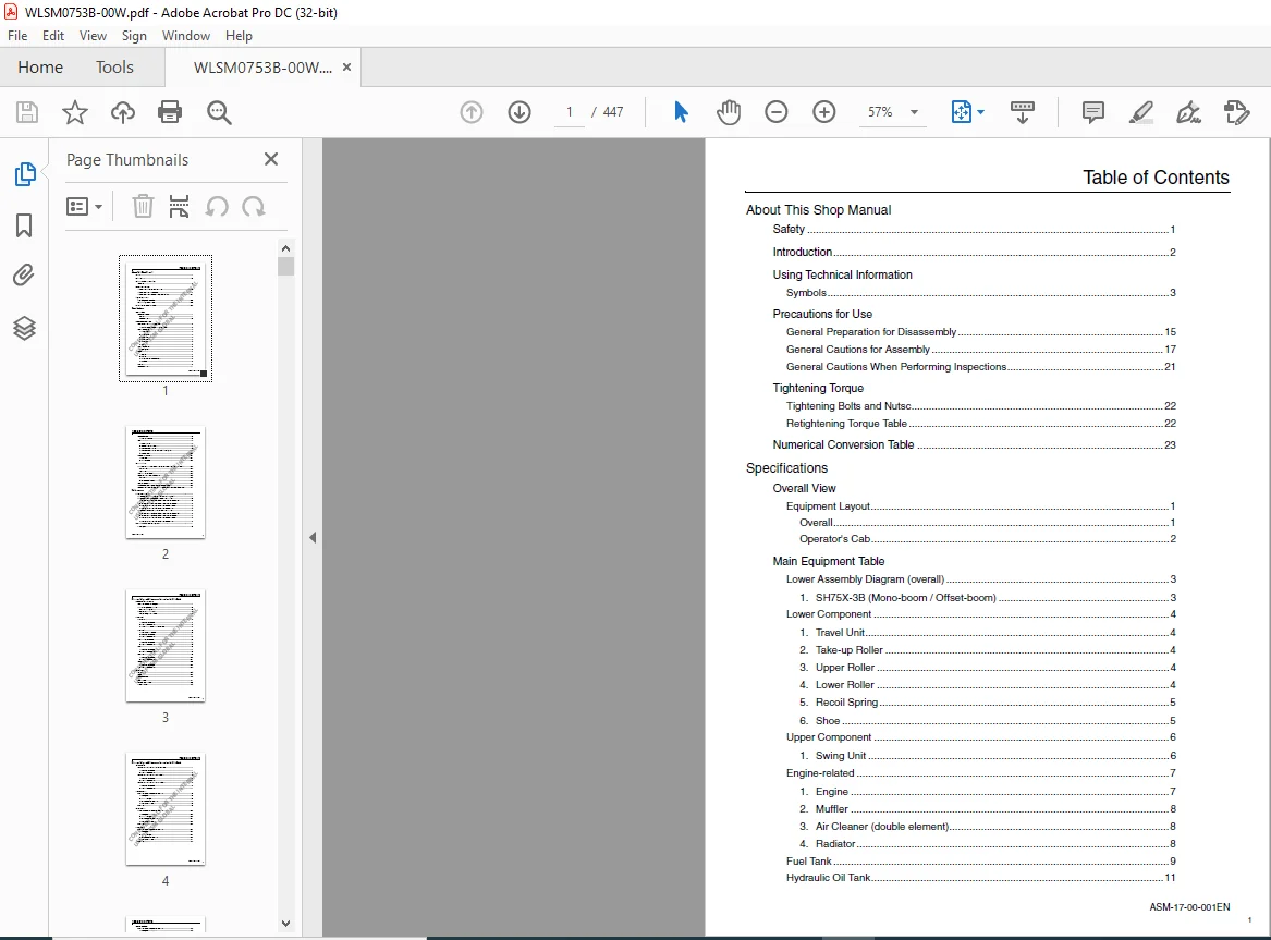
About This Shop Manual
Safety 1
Introduction 2
Using Technical Information
Symbols 3
Precautions for Use
General Preparation for Disassembly 15
General Cautions for Assembly 17
General Cautions When Performing Inspections 21
Tightening Torque
Tightening Bolts and Nutsc 22
Retightening Torque Table 22
Numerical Conversion Table 23
Specifications
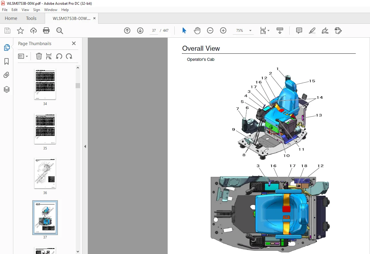
Overall View
Equipment Layout 1
Overall 1
Operator’s Cab 2
Main Equipment Table
Lower Assembly Diagram (overall) 3
1 SH75X-3B (Mono-boom / Offset-boom) 3
Lower Component 4
1 Travel Unit 4
2 Take-up Roller 4
3 Upper Roller 4
4 Lower Roller 4
5 Recoil Spring 5
6 Shoe 5
Upper Component 6
1 Swing Unit 6
Engine-related 7
1 Engine 7
2 Muffler 8
3 Air Cleaner (double element) 8
4 Radiator 8
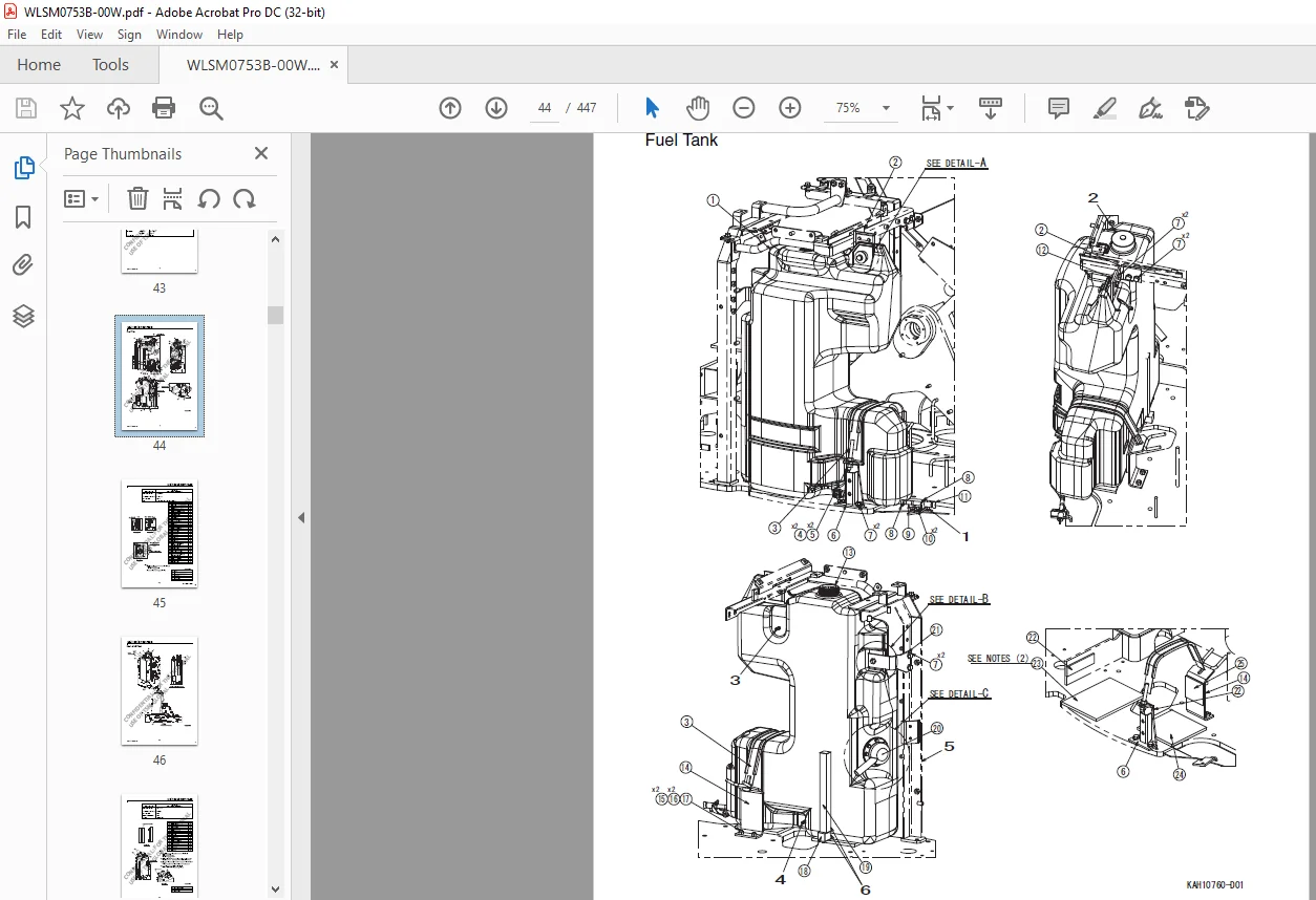
Fuel Tank 9
Hydraulic Oil Tank 11
1
ASM-17-00-001EN
Table of Contents
Hydraulic Device 13
1 Hydraulic Pump 13
Control-related 14
1 Control Valve 14
2 Solenoid Valve (3 stack) 14
3 Remote Control Valve 15
4 Remote Control Valve Characteristic Diagram 17
5 Center Joint 20
Backhoe Attachment 21
1 Cylinder 21
2 Attachments 23
Oil and Filters
Method of Use for Fuel and Lubricating Oil According to Air Temperature 24
Fuel and Oil 24
Anti-freeze 24
Sumitomo Genuine Parts 24
Engine Fuel and Filter Maintenance 25
Fuel Used 25
Filter and Maintenance 26
Consumable Parts 27
SH75X-3B Oil Feeding and Element Replacement 28
Replacement Times for Hydraulic Oil and Filters When Using the Breaker 31
Performances
Lifting Capacity 1
Precautions for Lifting Loads with the Hydraulic Excavator 1
Lifting Capacities SH75X-3B (Mono-boom with blade) 2
1 Standard Arm (1 71 m), 450 Grouser shoe (Blade down) 2
2 Standard Arm (1 71 m), 450 Grouser shoe (Blade up) 3
3 Long Arm (2 12 m), 450 Grouser shoe (Blade down) 4
4 Long Arm (2 12 m), 450 Grouser shoe (Blade up) 5
Lifting Capacities SH75X-3B (Offset-boom with blade) 6
1 Standard Arm (1 75 m), 450 Grouser shoe (Blade down) 6
2 Standard Arm (1 75 m), 450 Grouser shoe (Blade up) 7
3 Long Arm (2 10 m), 450 Grouser shoe (Blade down) 8
4 Long Arm (2 10 m), 450 Grouser shoe (Blade up) 9
Hydraulic Pump Control Diagram 10
P-Q Diagram 10
2
Table of Contents
ASM-17-00-001EN
Disassembling and Maintenance Instructions for Main Body
Maintenance Procedures
Lower Unit Path Block Diagram 1
Main Parts Tightening Torque 2
Bolt and Nut Tightening 2
Inspection and Maintenance 3
Retightening Torque Table 3
Lower Unit
Track Shoe 6
1 Removal Procedure 7
2 Installation Procedure 8
3 Track Link Replacement Procedure 9
Travel Unit 10
1 Assembly Precautions 10
2 Removal Procedure 11
3 Installation Procedure 12
Recoil Spring Assembly 13
1 Removal Procedure 14
2 Installation Procedure 15
Upper Roller 16
1 Removal Procedure 17
2 Installation Procedure 18
Lower Roller 19
1 Removal Procedure 20
2 Installation Procedure 21
Center Joint 22
1 Removal Procedure 23
2 Installation Procedure 24
Upper Unit
Swing Unit 25
Engine 28
Hydraulic Pump 30
Control Valve 31
Remote Control Valve 32
Operator’s Cab 35
3
Table of Contents
ASM-17-00-001EN
Disassembling and Maintenance Instructions for Main Body
Attachments
Removal and Installation of Bucket Cylinder 1
1 Removal Procedure 1
2 Installation Procedure 3
Removal and Installation of Arm Cylinder 5
1 Removal Procedure 5
2 Installation Procedure 7
Removal and Installation of Boom Cylinder 9
1 Removal Procedure 9
2 Installation Procedure 11
Take-up Roller
Assembly and Disassembly Procedures 13
1 Configuration Diagram 13
2 Tools and Jigs 13
3 Disassembly Procedures 14
4 Assembly Procedures 16
Assembly Diagram 19
Upper Roller
Disassembly and Assembly Procedures 20
1 Configuration Diagram 20
2 Tools and Jigs 20
3 Disassembly Procedures 21
4 Assembly Procedures 23
Assembly Diagram 26
Lower Roller
Assembly and Disassembly Procedures 27
1 Configuration Diagram 27
2 Tools and Jigs 27
3 Disassembly Procedures 28
4 Assembly Procedures 31
Assembly Diagram 34
4
ASM-17-00-001EN
Table of Contents
Grease Cylinder
Assembly and Disassembly Procedures 35
1 Configuration Diagram 35
2 Tools and jigs 35
3 Disassembly Procedures 36
4 Assembly procedure 37
Assembly Diagram 39
Center Joint
Assembly and Disassembly Procedures 40
1 Configuration Diagram 40
2 Tools and Jigs 41
3 Disassembly Procedures 42
4 Assembly Procedures 44
Assembly Diagram 46
SUMITOMO SH75X-3B HYDRAULIC EXCAVATOR REPAIR SERVICE MANUAL – PDF DOWNLOAD:
IMAGES PREVIEW OF THE MANUAL:


PLEASE NOTE:
- This is the same manual used by the dealers to diagnose and troubleshoot your vehicle
- You will be directed to the download page as soon as the purchase is completed. The whole payment and downloading process will take anywhere between 2-5 minutes
- Need any other service / repair / parts manual, please feel free to contact [email protected] . We still have 50,000 manuals unlisted
S.V