Trusted Business
Verified & Licensed
Virus Free Files
100% Safe Downloads
Secure Payment
SSL Protected
Instant Delivery
Available Immediately
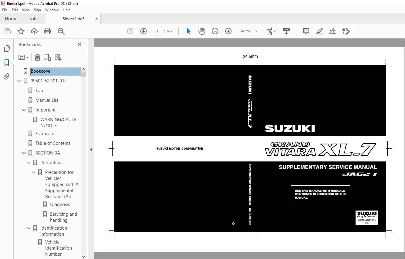
SUZUKI JA627 GRAND VITARA XL-7 SUPPLEMENTARY SERVICE MANUAL – PDF DOWNLOAD
$30.95
Instant PDF Download
Available immediately
Save to Your Device
Download & keep forever
Antivirus Scanned
100% virus-free
Trusted Worldwide
175,000+ customers
Description
SUZUKI JA627 GRAND VITARA XL-7 SUPPLEMENTARY SERVICE MANUAL – PDF DOWNLOAD
FILE DETAILS:
SUZUKI JA627 GRAND VITARA XL-7 SUPPLEMENTARY SERVICE MANUAL – PDF DOWNLOAD
Language : English
Pages : 657
Downloadable : Yes
File Type : PDF
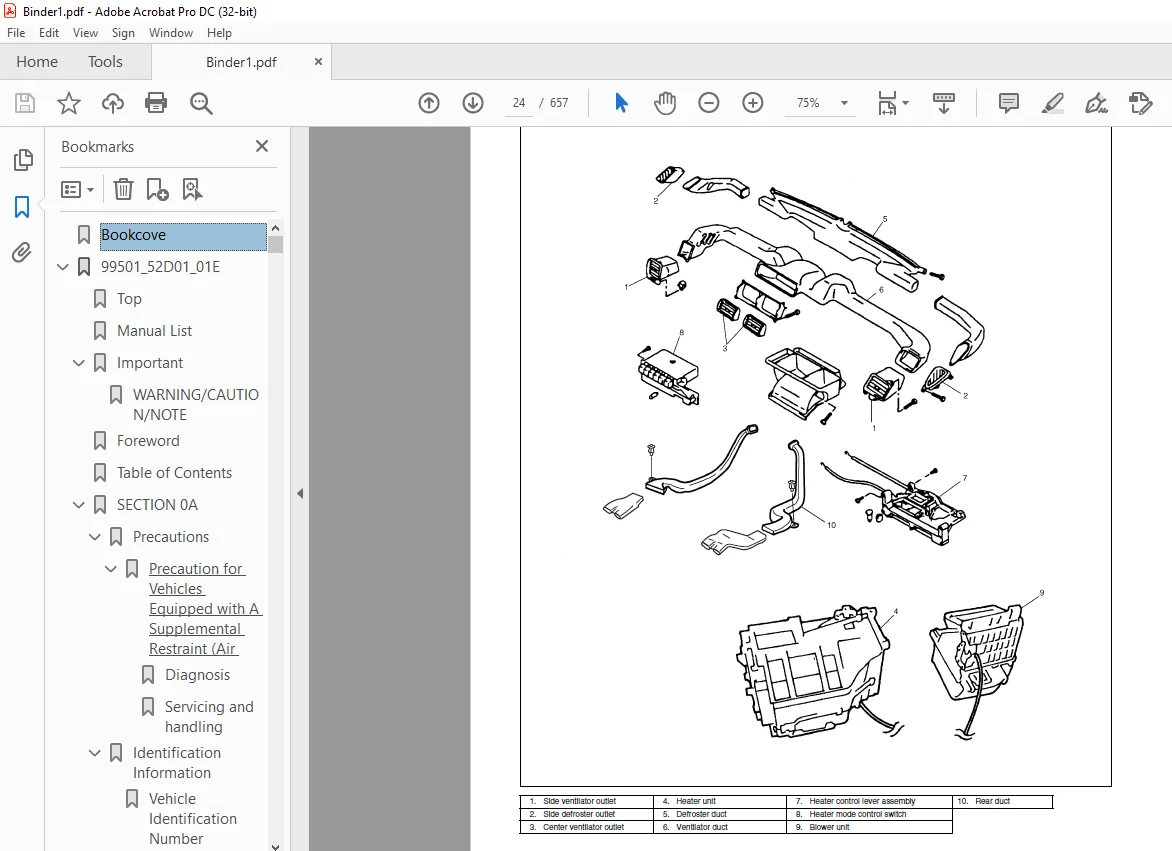
IMAGES PREVIEW OF THE MANUAL:
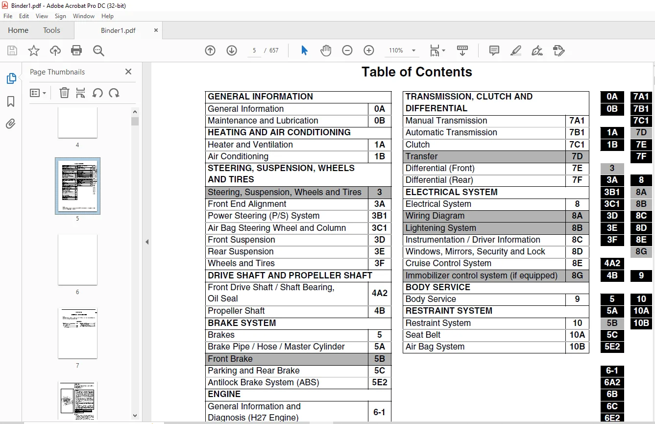
TABLE OF CONTENTS:
SUZUKI JA627 GRAND VITARA XL-7 SUPPLEMENTARY SERVICE MANUAL – PDF DOWNLOAD
Bookcove............................................................................................................  1
99501_52D01_01E.....................................................................................................  2
	Top.............................................................................................................  0
	Manual List.....................................................................................................  0
	Important.......................................................................................................  2
		WARNING/CAUTION/NOTE........................................................................................  2
	Foreword........................................................................................................  3
	Table of Contents...............................................................................................  5
	SECTION 0A......................................................................................................  7
		Precautions.................................................................................................  8
			Precaution for Vehicles Equipped with A Supplemental Restraint (Air Bag) System.........................  8
				Diagnosis...........................................................................................  8
				Servicing and handling..............................................................................  9
		Identification Information.................................................................................. 12
			Vehicle Identification Number........................................................................... 12
			Engine Identification Number............................................................................ 13
			Transmission Identification Number...................................................................... 13
		Warning, Caution and Information Labels..................................................................... 14
	SECTION 0B...................................................................................................... 15
		Maintenance Schedule........................................................................................ 16
			Maintenance Schedule under Normal Driving Conditions.................................................... 16
			Maintenance Recommended under Severe Driving Conditions................................................. 18
		Maintenance Service......................................................................................... 19
			Engine and Emission Control............................................................................. 19
				Drive belt inspection and replacement............................................................... 19
				Engine oil and filter replacement................................................................... 20
	SECTION 1A...................................................................................................... 23
		General Description......................................................................................... 24
			Rear Duct............................................................................................... 25
	SECTION 1B...................................................................................................... 27
		General Description......................................................................................... 29
			Refrigerant Type........................................................................................ 29
			Refrigerant Flow of Air Conditioning System............................................................. 29
			Major Components And Location........................................................................... 30
		Diagnosis................................................................................................... 32
			General................................................................................................. 32
				Main A/C system (front A/C system).................................................................. 32
				Rear A/C system..................................................................................... 34
			Quickly Checking of Refrigerant Charge (If Equipped with Sight Glass)................................... 35
			Performance Diagnosis................................................................................... 36
				Performance diagnosis table......................................................................... 38
				Detail diagnosis table (at ambient temperature within 30 - 35 °C (85 - 95 °F))...................... 39
			Wiring Circuit.......................................................................................... 40
			Inspection of A/C Controller and Its Circuits........................................................... 41
				Voltage check....................................................................................... 41
		Refrigerant Recovery, Evacuation and Charging............................................................... 45
			Operation Procedure for Charging A/C with Refrigerant................................................... 45
			Recovery................................................................................................ 46
			Evacuating.............................................................................................. 47
				Evacuating procedure................................................................................ 47
				Checking system for pressure leaks.................................................................. 48
			Charging................................................................................................ 48
		On-Vehicle Service.......................................................................................... 51
			Precaution.............................................................................................. 51
				Piping.............................................................................................. 51
				Handling refrigerant HFC-134a (R-134a).............................................................. 52
				Refrigerant recovery................................................................................ 52
				Refrigerant charge.................................................................................. 52
				Replenishing compressor oil......................................................................... 53
			Rear A/C Unit (Rear A/C Evaporator)..................................................................... 54
			Rear Expansion Valve.................................................................................... 55
			Rear A/C Evaporator Temperature Controller.............................................................. 56
			Refrigerant Pipes and Hoses............................................................................. 57
			Solenoid Valve.......................................................................................... 58
			Rear Blower Motor Assembly.............................................................................. 59
			Rear Blower Motor Relay and Solenoid Valve Relay........................................................ 60
			Rear A/C Main Switch.................................................................................... 60
			Rear Blower Motor Resistor.............................................................................. 61
			Rear Blower Motor Switch................................................................................ 62
			Rear A/C No.1 and No.2 Duct............................................................................. 63
				Rear A/C No.1 duct.................................................................................. 63
				Rear A/C No.2 duct.................................................................................. 63
			Compressor Assembly..................................................................................... 64
			Magnet Clutch........................................................................................... 67
		Required Service Materials.................................................................................. 70
		Tightening Torque Specification............................................................................. 70
		Special Tools............................................................................................... 70
	SECTION 3A...................................................................................................... 71
		General Information......................................................................................... 71
			Alignment Service Data (without Load)................................................................... 71
		On-Vehicle Service.......................................................................................... 71
			Reference Information................................................................................... 71
	SECTION 3B1..................................................................................................... 73
		General Description......................................................................................... 74
			Power Steering (P/S) Pump............................................................................... 74
		Diagnosis................................................................................................... 74
			Power Steering Pump Drive Belt.......................................................................... 74
				Belt inspection..................................................................................... 74
				Belt tension check.................................................................................. 74
				Belt tension adjustment............................................................................. 74
			Hydraulic Pressure in P/S Circuit....................................................................... 75
				Hydraulic pressure check............................................................................ 75
	SECTION 3C1..................................................................................................... 77
		General Description......................................................................................... 78
		Diagnosis................................................................................................... 79
			Inspection and Repair Required after Accident........................................................... 79
		On-Vehicle Service.......................................................................................... 79
			Service Precautions..................................................................................... 79
				Diagnosis and servicing............................................................................. 79
				Disabling air bag system............................................................................ 79
				Enabling air bag system............................................................................. 79
				Handling and storage................................................................................ 79
				Disposal............................................................................................ 79
			Steering Column......................................................................................... 80
			Steering Upper Shaft Assembly........................................................................... 83
			Steering Lower Shaft Assembly........................................................................... 85
			Checking Steering Column and Steering Upper Shaft for Accident Damage................................... 87
		Tightening Torque Specification............................................................................. 88
	SECTION 3D...................................................................................................... 89
		On-Vehicle Service.......................................................................................... 89
			Suspension Control Arm/Bushings......................................................................... 89
		Tightening Torque Specification............................................................................. 90
	SECTION 3E...................................................................................................... 91
		On-Vehicle Service.......................................................................................... 91
			Rear Axle Shaft and Wheel Bearing....................................................................... 91
			Rear Axle Shaft Inner Oil Seal.......................................................................... 95
			Rear Axle Housing....................................................................................... 95
		Tightening Torque Specification............................................................................. 96
		Required Service Material................................................................................... 96
		Special Tool................................................................................................ 97
	SECTION 3F...................................................................................................... 99
		General Description......................................................................................... 99
			Tires................................................................................................... 99
			Wheels.................................................................................................. 99
	SECTION 4A2.....................................................................................................101
		On-Vehicle Service..........................................................................................102
			Drive Shaft.............................................................................................102
		Required Service Material...................................................................................104
	SECTION 4B......................................................................................................105
		General Description.........................................................................................105
		On-Vehicle Service..........................................................................................106
			Propeller Shaft.........................................................................................106
		Tightening Torque Specification.............................................................................106
		Required Service Material...................................................................................106
	SECTION 5.......................................................................................................107
		Diagnosis...................................................................................................108
			Diagnosis Table.........................................................................................108
	SECTION 5A......................................................................................................109
		General Description.........................................................................................110
			Master Cylinder Assembly................................................................................110
		On-Vehicle Service..........................................................................................111
			Front Brake Hose/Pipe...................................................................................111
			Master Cylinder Reservoir...............................................................................114
			Master Cylinder Assembly................................................................................115
			Brake Booster...........................................................................................116
		Tightening Torque Specification.............................................................................118
		Special Tool................................................................................................118
	SECTION 5C......................................................................................................119
		General Description.........................................................................................120
			Drum Brake Assembly.....................................................................................120
		On-Vehicle Service..........................................................................................121
			Parking Brake Cable.....................................................................................121
			Brake Drum..............................................................................................121
			Wheel Cylinder..........................................................................................123
			Brake Back Plate........................................................................................123
		Tightening Torque Specification.............................................................................125
	SECTION 5E2.....................................................................................................127
		General Description.........................................................................................129
			Components/Parts Location...............................................................................129
			ABS Hydraulic Unit/control Module Assembly..............................................................130
				Self-diagnosis function.............................................................................130
				Fail-safe function..................................................................................130
		Diagnosis...................................................................................................131
			Precautions in Diagnosing Troubles......................................................................131
			ABS Diagnostic Flow Table...............................................................................132
			ABS Warning Lamp Check..................................................................................135
			EBD Warning Lamp (Brake Warning Lamp) Check.............................................................135
			Diagnostic Trouble Code (DTC) Check (Using ABS Warning Lamp)............................................136
			Diagnostic Trouble Code (DTC) Check (Using SUZUKI Scan Tool)............................................137
			Diagnostic Trouble Code (DTC) Clearance.................................................................137
			Diagnostic Trouble Code (DTC) Table.....................................................................138
			System Circuit..........................................................................................140
			Table-A ABS Warning Lamp Circuit Check – Lamp Does Not Come “ON” at Ignition Switch ON..................141
			Table-B ABS Warning Lamp Circuit Check – Lamp Comes “ON” Steady.........................................142
			Table-C ABS Warning Lamp Circuit Check – The Lamp Flashes Continuously While Ignition Switch Is ON......143
			Table-D Code (DTC) Is Not Outputted Even with Diagnosis Switch Terminal Connected to Ground.............144
			Table-E EBD Warning Lamp (Brake Warning Lamp) Check – Lamp Comes “ON” Steady............................145
			DTC C1015 (DTC 15) – G Sensor Circuit and 4WD Lamp Circuit..............................................146
			DTC C1021 (DTC 21), DTC C1022 (DTC 22) – Right-Front Wheel Speed Sensor Circuit or Sensor Ring..........148
			DTC C1025 (DTC 25), DTC C1026 (DTC 26) – Left-Front Wheel Speed Sensor Circuit or Sensor Ring...........148
			DTC C1031 (DTC 31), DTC C1032 (DTC 32) – Right-Rear Wheel Speed Sensor Circuit or Sensor Ring...........148
			DTC C1035 (DTC 35), DTC C1036 (DTC 36) – Left-Rear Wheel Speed Sensor Circuit or Sensor Ring............148
			DTC C1041 (DTC 41) – Right-Front Inlet Solenoid Circuit.................................................150
			DTC C1045 (DTC 45) – Left-Front Inlet Solenoid Circuit..................................................150
			DTC C1055 (DTC 55) – Rear Inlet Solenoid Circuit........................................................150
			DTC C1042 (DTC 42) – Right-Front Outlet Solenoid Circuit................................................150
			DTC C1046 (DTC 46) – Left-Front Outlet Solenoid Circuit.................................................150
			DTC C1056 (DTC 56) – Rear Outlet Solenoid Circuit.......................................................150
			DTC C1057 (DTC 57) – Power Source Circuit...............................................................151
			DTC C1061 (DTC 61) – ABS Pump Motor Circuit.............................................................152
			DTC C1063 (DTC 63) – ABS Fail-Safe Relay Circuit........................................................153
			DTC C1071 (DTC 71) – ABS Control Module.................................................................154
		On-Vehicle Service..........................................................................................155
			Precautions.............................................................................................155
			ABS Hydraulic Unit Operation Check (Using SUZUKI Scan Tool).............................................155
			ABS Hydraulic Unit Operation Check (Not Using Suzuki Scan Tool).........................................155
			ABS Hydraulic Unit/Control Module Assembly..............................................................157
			Rear Sensor Rotor (Retainer Ring).......................................................................159
		Tightening Torque Specification.............................................................................160
		Special Tool................................................................................................160
	SECTION 6-1.....................................................................................................163
		General Information.........................................................................................165
			Statement of Cleanliness and Care.......................................................................165
			General Information on Engine Service...................................................................165
			Precaution on Fuel System Service.......................................................................166
			Fuel Pressure Relief Procedure..........................................................................167
			Fuel Leakage Check Procedure............................................................................167
		Engine Diagnosis............................................................................................168
			General Description.....................................................................................168
			On-Board Diagnostic System (Vehicle without Monitor Connector)..........................................168
			On-Board Diagnostic System (Vehicle with Monitor Connector).............................................171
			Precaution in Diagnosing Trouble........................................................................172
			Engine Diagnostic Flow Table............................................................................173
			Malfunction Indicator Lamp (MIL) Check..................................................................178
			Diagnostic Trouble Code (DTC) Check.....................................................................178
			Diagnostic Trouble Code (DTC) Clearance.................................................................179
			Diagnostic Trouble Code (DTC) Table.....................................................................180
				For A/T system (Refer to Section 7B1 for diagnosis).................................................183
				For immobilizer control system (Refer to Section 8G for diagnosis)..................................184
			Fail-Safe Table.........................................................................................185
			Scan Tool Data..........................................................................................186
				Scan tool data definitions..........................................................................189
			Engine Diagnosis Table..................................................................................193
			Inspection of PCM (ECM) and its Circuits................................................................198
			Table A-1 Malfunction Indicator Lamp Circuit Check – Lamp Does Not Come “ON” or Dims at Ignition .......205
			Table A-2 Malfunction Indicator Lamp Circuit Check – Lamp Remains “ON” after Engine Starts..............206
			Table A-3 Malfunction Indicator Lamp Check – MIL Flashes at Ignition Switch ON (Vehicle with Moni.......207
			Table A-4 Malfunction Indicator Lamp Check – MIL Does Not Flash or Just Remains ON Even with Grou.......207
			Table A-5 ECM (PCM) Power and Ground Circuit Check – MIL Doesn’t Light at Ignition Switch ON and .......208
			DTC P0100 (DTC No.33, 34) Mass Air Flow Circuit Malfunction.............................................210
			DTC P0110 (DTC No.23, 25) Intake Air Temp. (IAT) Circuit Malfunction....................................212
			DTC P0115 (DTC No.14, 15) Engine Coolant Temp. Circuit Malfunction......................................214
			DTC P0120 (DTC No.21, 22) Throttle Position Circuit Malfunction.........................................216
			DTC P0121 Throttle Position Circuit Range/Performance Problem...........................................218
			DTC P0130 (DTC No.13) HO2S-1 (Bank 1) Circuit Malfunction or No Activity Detected.......................220
			DTC P0133 HO2S-1 (Bank 1) Circuit Slow Response.........................................................222
			DTC P0135 HO2S-1 (Bank 1) Heater Circuit Malfunction....................................................223
			DTC P0136 HO2S-2 (Bank 1) Circuit Malfunction...........................................................225
			DTC P0141 HO2S-2 (Bank 1) Heater Circuit Malfunction....................................................227
			DTC P0150 (DTC No.26) HO2S-1 (Bank 2) Circuit Malfunction or No Activity Detected.......................229
			DTC P0153 HO2S-1 (Bank 2) Circuit Slow Response.........................................................231
			DTC P0155 HO2S-1 (Bank 2) Heater Circuit Malfunction....................................................232
			DTC P0156 HO2S-2 (Bank 2) Circuit Malfunction...........................................................234
			DTC P0161 HO2S-2 (Bank 2) Heater Circuit Malfunction....................................................236
			DTC P0171/P0172 Fuel System Too Lean/Rich (Bank 1)......................................................238
			DTC P0174/P0175 Fuel System Too Lean/Rich (Bank 2)......................................................240
			DTC P0300/P0301/P0302/P0303/P0304/P0305/P0306 Random Misfire/Cylinder 1 Misfire/Cylinder 2 Misfir.......242
			DTC P0325 (DTC No.43) Knock Sensor Circuit Malfunction..................................................244
			DTC P0335 Crankshaft Position Sensor Circuit Malfunction................................................246
			DTC P0340 (DTC No.42) Camshaft Position Sensor Circuit Malfunction......................................248
			DTC P0400 Exhaust Gas Recirculation Flow Malfunction....................................................251
			DTC P0403 (DTC No.51) Exhaust Gas Recirculation Circuit Malfunction.....................................254
			DTC P0420 Catalyst System Efficiency Below Threshold (Bank 1)...........................................256
			DTC P0430 Catalyst System Efficiency Below Threshold (Bank 2)...........................................258
			DTC P0443 Evap Control System Purge Control Valve Circuit Malfunction...................................260
				Evap canister purge system inspection...............................................................262
				Vacuum passage inspection...........................................................................262
				Vacuum hose inspection..............................................................................263
				Evap canister purge valve and its circuit inspection................................................263
				Evap canister purge valve inspection................................................................263
			DTC P0460 Fuel Level Sensor Circuit High Input..........................................................265
			DTC P0500 (DTC No.24) Vehicle Speed Sensor Malfunction..................................................267
			DTC P0505 Idle Air Control System Malfunction...........................................................270
			DTC P0601 (DTC No.71) Internal Control Module Memory Check Sum Error....................................272
			DTC P1408 Manifold Absolute Pressure Sensor Circuit Malfunction.........................................273
			DTC P1450/P1451 Barometric Pressure Sensor Circuit Malfunction/Performance Problem......................275
			DTC P1500 Engine Starter Signal Circuit Malfunction.....................................................276
			DTC P1510 Ecm Back-Up Power Supply Malfunction..........................................................277
			Table B-1 Fuel Pump Circuit Inspection..................................................................278
			Table B-2 Fuel Injectors and Circuit Inspection.........................................................279
			Table B-3 Fuel Pressure Inspection......................................................................281
			Table B-4 Idle Air Control System Inspection............................................................283
			Table B-5 A/C Signal Circuits Inspection (If Equipped)..................................................285
			Table B-6 A/C Condenser Fan Motor Relay Control System Inspection (If Equipped).........................286
		Special Tool................................................................................................287
	SECTION 6A2.....................................................................................................289
		On-Vehicle Service..........................................................................................290
			Throttle Body and Intake Manifold.......................................................................290
			Exhaust Manifold........................................................................................297
			LH (No.1) Bank 2nd Timing Chain and Chain Tensioner.....................................................301
			Camshaft and Valve Lash Adjuster........................................................................302
			Valves and Cylinder Heads...............................................................................305
			Piston, Piston Rings, Connecting Rods and Cylinders.....................................................309
		Unit Repair Overhaul........................................................................................314
			Engine Assembly.........................................................................................314
			Main Bearings, Crankshaft and Cylinder Block............................................................318
		Special Tool................................................................................................324
	SECTION 6B......................................................................................................327
		Maintenance.................................................................................................328
			Coolant.................................................................................................328
	SECTION 6C......................................................................................................329
		General Description.........................................................................................329
			Fuel System.............................................................................................329
		On-Vehicle Service..........................................................................................330
			Fuel Tank...............................................................................................330
			Fuel Lines..............................................................................................333
	SECTION 6E2.....................................................................................................335
		General Description.........................................................................................336
			System Flow.............................................................................................337
			System Diagram..........................................................................................338
			Air Intake System.......................................................................................340
			Fuel Delivery System....................................................................................341
			Electronic Control System...............................................................................342
			Engine and Emission Control Input/Output Table..........................................................346
		Diagnosis...................................................................................................346
		On-Vehicle Service..........................................................................................347
			General.................................................................................................347
			Accelerator Cable Adjustment............................................................................348
			A/T Throttle Cable Adjustment (A/T Vehicle).............................................................348
			Idle Speed/Idle Air Control (IAC) Duty Inspection.......................................................349
				[Using SUZUKI scan tool]............................................................................349
				[Not using SUZUKI scan tool] (vehicle with monitor connector).......................................350
				Idle mixture inspection/adjustment (vehicle without heated oxygen sensor)...........................351
			Air Intake System.......................................................................................352
				Throttle body.......................................................................................352
				Idle air control valve (IAC valve)..................................................................355
				Fast idle air valve.................................................................................356
			Fuel Delivery System....................................................................................357
				Fuel pressure inspection............................................................................357
				Fuel pump...........................................................................................358
				Fuel pressure regulator.............................................................................359
				Fuel injector.......................................................................................360
			Electronic Control System...............................................................................365
				Engine control module (ECM)/powertrain control module (PCM).........................................365
				Mass air flow sensor (MAF sensor)...................................................................366
				Intake air temperature (IAT) sensor.................................................................368
				Throttle position sensor (TP sensor)................................................................369
				Engine coolant temperature sensor (ECT sensor)......................................................370
				Heated oxygen sensor (sensor 1).....................................................................371
				Heated oxygen sensor (sensor 2).....................................................................372
				Vehicle speed sensor (VSS)..........................................................................373
				Manifold absolute pressure sensor...................................................................373
				Fuel level sensor (sender gauge)....................................................................375
				Crankshaft position sensor..........................................................................375
				Main relay..........................................................................................375
				Fuel pump relay.....................................................................................376
				Fuel cut operation..................................................................................377
			Emission Control System.................................................................................378
				EGR system (if equipped)............................................................................378
				EVAP canister.......................................................................................379
				Vacuum passage......................................................................................380
			PCV System..............................................................................................381
				PCV hose............................................................................................381
				PCV valve...........................................................................................381
				PCV system..........................................................................................382
		Tightening Torque Specification.............................................................................382
		Special Tool................................................................................................382
	SECTION 6F2.....................................................................................................385
		General Description.........................................................................................386
			Components..............................................................................................386
			System Wiring...........................................................................................387
		Diagnosis...................................................................................................388
			Diagnostic Flow Table...................................................................................388
			Ignition Spark Check....................................................................................390
			Ignition Timing Check and Adjustment....................................................................390
		On-Vehicle Service..........................................................................................392
			Ignition Coil Assembly (Igniter and Ignition Coil)......................................................392
			Spark Plug..............................................................................................392
			CMP Sensor..............................................................................................394
			Noise Suppressor........................................................................................396
		Special Tool................................................................................................397
	SECTION 6H......................................................................................................399
		General Description.........................................................................................400
			Generator...............................................................................................400
		Unit Repair Overhaul........................................................................................401
			Generator Assembly......................................................................................401
				Inspection..........................................................................................401
		Specifications..............................................................................................404
			Battery.................................................................................................404
			Generator...............................................................................................404
		Tightening Torque Specification.............................................................................404
	SECTION 6K......................................................................................................405
		On-Vehicle Service..........................................................................................406
			Components..............................................................................................406
	SECTION 7A1.....................................................................................................409
		Unit Repair.................................................................................................409
	SECTION 7B1.....................................................................................................411
		General Description.........................................................................................413
			Electronic Shift Control System.........................................................................414
				Automatic gear shift diagram........................................................................415
		Diagnosis...................................................................................................417
			On-Board Diagnostic System (Vehicle without monitor connector)..........................................417
			On-Board Diagnostic System (Vehicle with monitor connector).............................................418
			Precaution in Diagnosing Trouble........................................................................419
			Automatic Transmission Diagnostic Flow Table............................................................420
			Malfunction Indicator Lamp (MIL) Check..................................................................423
			“O/D OFF” Lamp Check....................................................................................423
			“POWER” Lamp Check......................................................................................423
			Diagnostic Trouble Code (DTC) Check.....................................................................423
			Diagnostic Trouble Code Clearance.......................................................................423
			Diagnostic Trouble Code Table...........................................................................424
			Fail Safe Table.........................................................................................424
			Visual Inspection.......................................................................................424
			A/T Basic Check.........................................................................................424
			Trouble Diagnosis Table 1...............................................................................425
			Trouble Diagnosis Table 2...............................................................................425
			Trouble Diagnosis Table 3...............................................................................426
			Scan Tool Data..........................................................................................427
			Inspection of PCM and Its Circuit.......................................................................427
			Wire Harness and Connectors.............................................................................427
			Table A-1 : No TCC Lock-Up Occurs.......................................................................428
			Table A-2 : No Gear Shift to O/D........................................................................430
			Table B-1 : “O/D OFF” Light Circuit Check (“O/D OFF” Light Doesn’t Light at Ignition Switch ON Bu.......432
			Table B-2 : “O/D OFF” Light Circuit Check (“O/D OFF” Light Comes ON Steadily)...........................433
			Table B-3 : “POWER” Light Circuit Check (“POWER” Light Doesn’t Light at Ignition Switch ON But En.......434
			Table B-4 : “POWER” Light Circuit Check (“POWER” Light Comes ON Steadily)...............................435
			DTC P0705 (DTC NO.72) - Transmission Range Sensor (Switch) Circuit Malfunction..........................436
			DTC P0715 (DTC NO.76) - Input/Turbine Speed Sensor Circuit Malfunction..................................439
			DTC P0720 (DTC NO.75) Output Speed Sensor Circuit Malfunction...........................................442
			DTC P0743 (DTC NO.65/66) - TCC (Lock-Up) Solenoid Electrical............................................444
			DTC P0753 (DTC NO.61/62) Shift Solenoid-A (#1) Electrical DTC P0758 (DTC NO.63/64) Shift Solenoid.......446
			Stall Test..............................................................................................448
			Line Pressure Test......................................................................................449
			Road Test...............................................................................................450
			Manual Road Test........................................................................................451
			Time Lag Test...........................................................................................451
			Engine Brake Test.......................................................................................452
			“P” Range Test..........................................................................................452
		On-Vehicle Service..........................................................................................453
			Maintenance Service.....................................................................................453
				Fluid level.........................................................................................453
				Fluid change........................................................................................454
			A/T Throttle Cable......................................................................................455
			Solenoid Valves (Shift Solenoid Valves and TCC Solenoid Valve)..........................................455
			MANUAL SELECTOR ASSEMBLY................................................................................456
			SELECT CABLE............................................................................................458
		Unit Repair.................................................................................................459
			Sub-Assembly Repair.....................................................................................459
				Overdrive (case side)...............................................................................459
				Forward clutch......................................................................................460
				Front upper valve body..............................................................................464
			Unit Assembly...........................................................................................469
		Tightening Torque Specification.............................................................................470
		Special Tool................................................................................................471
	SECTION 7C1.....................................................................................................473
	SECTION 7E......................................................................................................475
		General Description.........................................................................................476
			4WD Control System......................................................................................476
				System circuit......................................................................................476
		Diagnosis...................................................................................................477
			Differential Assembly Diagnosis Table...................................................................477
			4WD Control System Diagnostic Flow Table................................................................477
				Notes on system circuit inspection..................................................................477
				Flow table..........................................................................................478
			4WD Control System Circuit Inspection...................................................................479
				Voltage check.......................................................................................479
			4WD Control System Inspection...........................................................................480
		On-Vehicle Service..........................................................................................481
			Differential Mountings..................................................................................481
			Rear Mounting for Front Differential Carrier............................................................482
			Front Differential Assembly.............................................................................483
		Unit Repair.................................................................................................485
		Tightening Torque Specification.............................................................................485
		Special Tool................................................................................................485
	SECTION 7F......................................................................................................487
		General Description.........................................................................................488
		Diagnosis...................................................................................................488
			Diagnosis Table.........................................................................................488
		On-Vehicle Service..........................................................................................489
			Precaution for Maintenance Service......................................................................490
			Differential Gear Oil Change............................................................................490
			Rear Differential Assembly..............................................................................491
				Dismounting.........................................................................................491
				Remounting..........................................................................................491
		Unit Repair.................................................................................................492
			Disassembling Unit......................................................................................492
			Component Inspection....................................................................................495
			Sub-Assembly Adjustment and Reassembly..................................................................495
				Differential carrier................................................................................496
				Differential case...................................................................................496
				Differential side bearing...........................................................................498
				Drive bevel pinion..................................................................................499
			Assembling Unit.........................................................................................504
		Tightening Torque Specification.............................................................................507
		Required Service Material...................................................................................507
		Special Tool................................................................................................508
	SECTION 8.......................................................................................................511
		General Description.........................................................................................512
	SECTION 8C......................................................................................................513
		General Description.........................................................................................514
			Combination Meter.......................................................................................514
		On-vehicle Service..........................................................................................516
			Fuel Meter/Fuel Gauge Unit..............................................................................516
				Fuel level sensor (sender gauge)....................................................................516
			Engine Coolant Temperature (ECT) Meter and Sensor.......................................................517
				Engine coolant temperature sensor...................................................................517
			Oil Pressure Light......................................................................................517
				Oil pressure switch.................................................................................517
			Brake Warning Light.....................................................................................517
				Brake fluid level switch............................................................................517
	SECTION 8D......................................................................................................519
		General Description.........................................................................................520
			Rear Wiper and Washer (If Equipped).....................................................................520
		On-Vehicle Service..........................................................................................521
			Windshield Wipers.......................................................................................521
				Front wiper and washer..............................................................................521
			Rear Window Wiper and Washer (For Vehicle with Cruise Control System)...................................522
				Rear Wiper and Washer Switch........................................................................522
			Rear Window Wiper and Washer (For Vehicle without Cruise Control System)................................522
			Rear Wiper Intermittent Relay...........................................................................522
	SECTION 8E......................................................................................................523
		General Description.........................................................................................524
			Cautions in Servicing...................................................................................524
			Symbols and Marks.......................................................................................524
			Abbreviations...........................................................................................524
			Wiring Color Symbols....................................................................................524
			Joint Connector.........................................................................................524
			Fuse Box and Relay......................................................................................524
			Power Supply Diagram....................................................................................524
			Cruise Control System...................................................................................525
				Cruise control system circuit.......................................................................525
				Components and functions............................................................................526
				Cancel Conditions...................................................................................527
		Diagnosis...................................................................................................527
			Diagnosis Table.........................................................................................527
			Note on System Circuit Inspection.......................................................................529
			Cruise Main Switch Indicator Lamp Circuit Check.........................................................530
			“Cruise” Indicator Lamp Circuit Check...................................................................531
			Cruise Main Switch, Coast/Set, Resume/Accel and Cancel Switches Circuits Check..........................532
			VSS Circuit Check.......................................................................................533
			Stop Lamp Switch (with Pedal Position Switch) Circuits Check............................................534
			Transmission Range Switch Circuit Check.................................................................535
			Clutch Pedal Position Switch Circuit Check..............................................................536
			Throttle Valve Opening Signal Circuit Check.............................................................537
			Overdrive and TCC off Command Signal Circuit Check......................................................538
			Cruise Control Module Power and Ground Circuits Check...................................................538
			Cruise Control Module and Its Circuit Inspection........................................................539
			Cruise Cable Play Inspection and Adjustment.............................................................541
		On-Vehicle Service..........................................................................................541
			Cruise Main Switch......................................................................................541
			Coast/Set, Resume/Accel and Cancel Switches.............................................................542
			Vehicle Speed Sensor (VSS)..............................................................................542
			Transmission Range Switch...............................................................................542
			Clutch Pedal Position (CPP) Switch......................................................................543
			Stop Lamp Switch (with Pedal Position Switch)...........................................................544
			Cruise Control Actuator Assembly (with Control Module)..................................................545
			Cruise Cable............................................................................................546
	SECTION 9.......................................................................................................547
		Glass, Windows and Mirror...................................................................................548
			Quarter Window..........................................................................................548
		Body Structure..............................................................................................549
			Under Body Dimensions...................................................................................549
			Body Dimensions.........................................................................................550
		Seat........................................................................................................554
			Second Seat.............................................................................................554
			Third Seat (If Equipped)................................................................................555
		Paint and Coatings..........................................................................................556
			Sealant Application Area................................................................................556
			Undercoating/Anti-corrosion Compound Application Area...................................................563
		Exterior and Interior Trim..................................................................................565
			Floor Carpet............................................................................................565
				Front floor carpet..................................................................................565
				Rear floor carpet (without third seat vehicle)......................................................566
			Head Lining.............................................................................................566
	SECTION 10......................................................................................................569
		General Description.........................................................................................570
	SECTION 10A.....................................................................................................571
		On-Vehicle Service..........................................................................................572
			Service Precautions.....................................................................................572
				Service and diagnosis...............................................................................572
				Disabling air bag system............................................................................572
				Enabling air bag system.............................................................................572
				Handling and storage................................................................................572
				Disposal............................................................................................572
			Front Seat Belt.........................................................................................573
			Second Rear Seat Belt...................................................................................576
			Third Rear Seat Belt (If Equipped)......................................................................577
		Tightening Torque Specification.............................................................................578
	SECTION 10B.....................................................................................................579
		General Description.........................................................................................581
			System Components and Wiring Location View and Connectors...............................................582
			System Wiring Diagram...................................................................................583
		Diagnosis...................................................................................................584
			Diagnostic Trouble Code (DTC)...........................................................................584
			Use of Special Tool.....................................................................................584
			Intermittents and Poor Connections......................................................................586
			Air Bag Diagnostic System Check.........................................................................587
			Air Bag Diagnostic System Check Flow Table..............................................................588
			DTC Check...............................................................................................589
			DTC Clearance...........................................................................................590
			DTC Table...............................................................................................592
			Table A - “AIR BAG” Warning Lamp Comes ON Steady........................................................594
			Table B - “AIR BAG” Warning Lamp Does Not Come ON.......................................................594
			Table C - “AIR BAG” Warning Lamp Flashes................................................................594
			Table D - “AIR BAG” Warning Lamp Cannot Indicate Flashing Pattern of DTC................................594
			Table E - SDM Cannot Communicate through The Serial Data Circuit........................................599
			DTC B1015 - Passenger Air Bag Initiator Circuit Resistance High.........................................601
			DTC B1016 - Passenger Air Bag Initiator Circuit Resistance Low..........................................601
			DTC B1018 - Passenger Air Bag Initiator Circuit Short to Ground.........................................601
			DTC B1019 - Passenger Air Bag Initiator Circuit Short to Power Circuit..................................601
			DTC B1021 – Driver Air Bag Initiator Circuit Resistance High............................................606
			DTC B1022 – Driver Air Bag Initiator Circuit Resistance Low.............................................606
			DTC B1024 – Driver Air Bag Initiator Circuit Short to Ground............................................606
			DTC B1025 – Driver Air Bag Initiator Circuit Short to Power Circuit.....................................606
			DTC B1031 – Power Source Voltage High...................................................................611
			DTC B1032 – Power Source Voltage Low....................................................................611
			DTC B1035 – RH Forward Sensor Circuit Open or Short to Ground...........................................614
			DTC B1036 – RH Forward Sensor Circuit Short Between Two Wires or Short to Power Circuit.................614
			DTC B1037 – LH Forward Sensor Circuit Open or Short to Ground...........................................614
			DTC B1038 – LH Forward Sensor Circuit Short Between Two Wires or Short to Power Circuit.................614
			DTC B1041 – Driver Pretensioner Initiator Circuit Resistance High.......................................618
			DTC B1042 – Driver Pretensioner Initiator Circuit Resistance Low........................................618
			DTC B1043 – Driver Pretensioner Initiator Circuit Short to Ground.......................................618
			DTC B1044 – Driver Pretensioner Initiator Circuit Short to Power Circuit................................618
			DTC B1045 – Passenger Pretensioner Initiator Circuit Resistance High....................................618
			DTC B1046 – Passenger Pretensioner Initiator Circuit Resistance Low.....................................618
			DTC B1047 – Passenger Pretensioner Initiator Circuit Short to Ground....................................618
			DTC B1048 – Passenger Pretensioner Initiator Circuit Short to Power Circuit.............................618
			DTC B1051 – Frontal Crash Detected (System Activation Command Outputted)................................624
			DTC B1061 – “AIR BAG” Warning Lamp Circuit Failure......................................................625
			DTC B1071 – Internal SDM Fault..........................................................................626
			DTC B1013 – System Specifications Different from SDM Specifications.....................................626
		On-Vehicle Service..........................................................................................627
			Service Precautions.....................................................................................627
				Service and diagnosis...............................................................................627
				Disabling air bag system............................................................................628
				Enabling air bag system.............................................................................628
				Handling and storage................................................................................629
			Repairs and Inspections Required after an Accident......................................................634
				Accident with deployment/activation - component replacement.........................................634
				Accident with or without deployment/activation - component inspections..............................635
			SDM.....................................................................................................638
			Forward Sensor..........................................................................................640
			Seat Belt Pretensioner..................................................................................642
		Air Bag (Inflator) Module and Seat Belt Pretensioner Disposal...............................................643
			Deployment/Activation Outside Vehicle...................................................................644
			Deployment/Activation Inside Vehicle....................................................................650
			Deployed Air Bag (Inflator) Module and Activated Seat Belt Pretensioner Disposal........................654
		Tightening Torque Specification.............................................................................655
		Special Tool................................................................................................655
	Copyright.......................................................................................................657
	bookcover.......................................................................................................  0
S.S